4 layers134 × 33 mm

 anders-bzn/nixie-clock1
Rasberry Pi nixie clock with six digits and NTP sync
Nixie clock psu is an open-source printed circuit board by anders-bzn, from the anders-bzn/nixie-clock repository on GitHub. It is a 4-layer board of 65 × 33 mm with 26 parts on 11 nets, routed with 114 tracks and 91 vias.
It is built around the 100UF 10V 4*7, ES2F and IRF644. Its parts include 11 capacitors, 3 resistors, 2 ICs, 2 connectors and 2 inductors. It belongs with the lEDs and displays and power boards of this library.


This is a clock powered by a Raspberry Pi Zero W. It fetches current time by NTP and must be connected to a WiFi network to display the time.
The time is displayed on six IN-14 nixie tubes driven by six 74141. No multiplexing! The intensity can be adjusted by PWM.
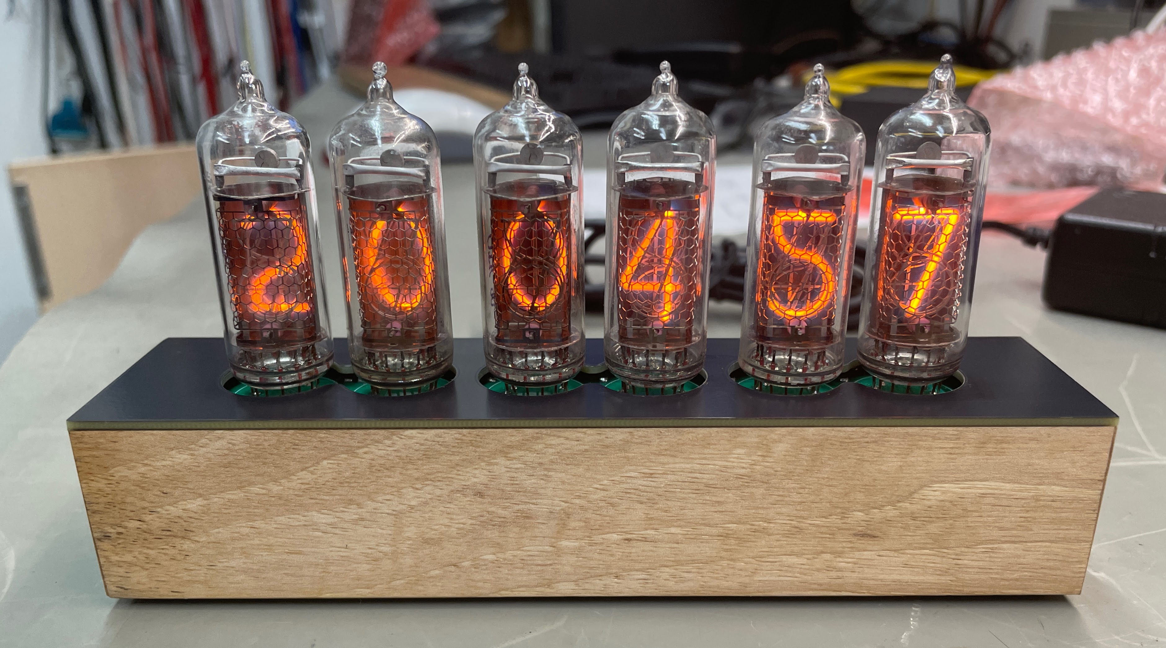
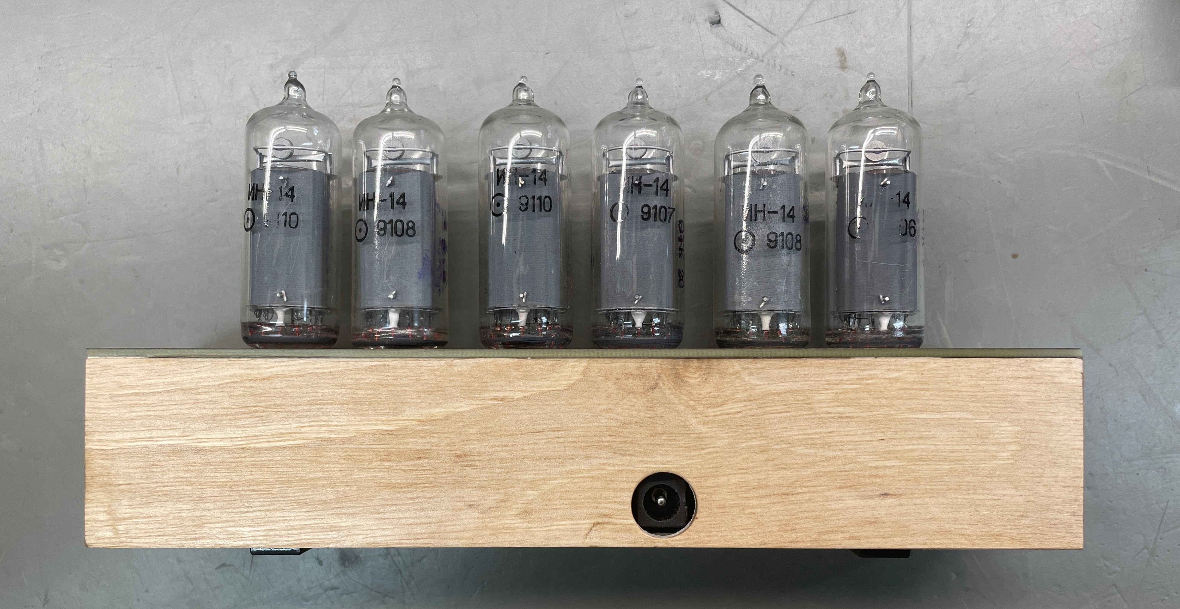
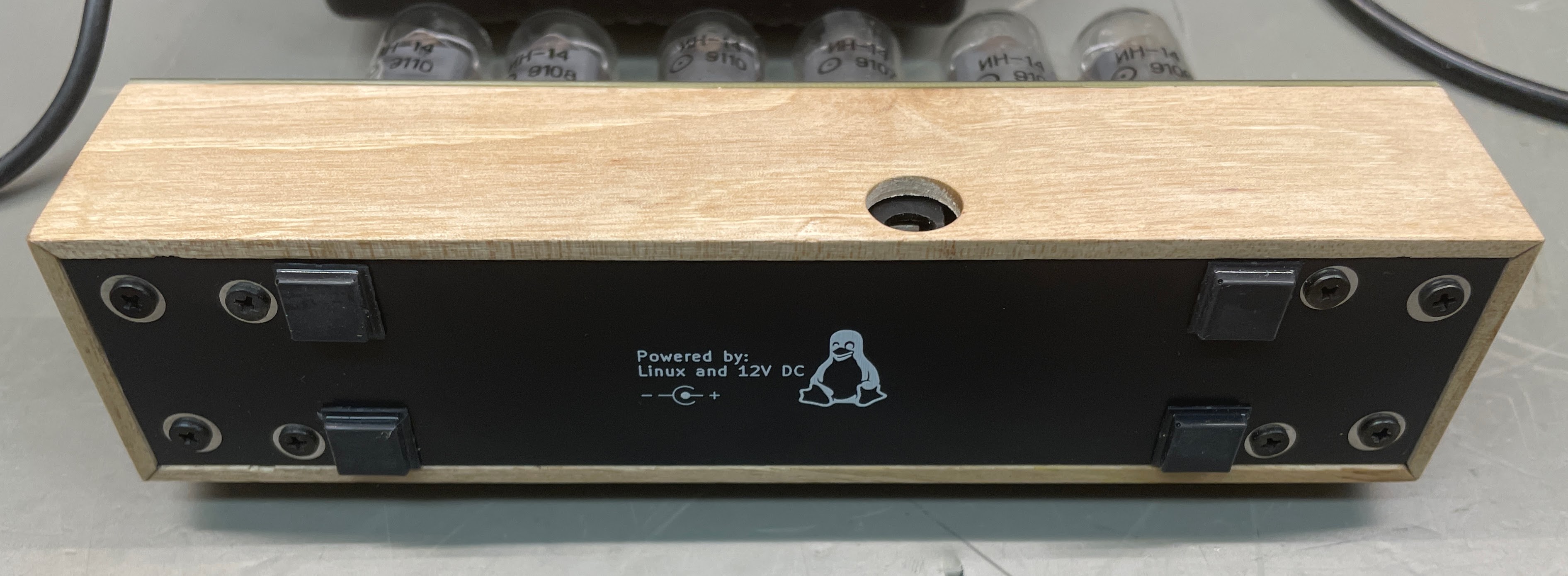
There are in total five PCB's in this project. All boards are drawn with KiCad 8.0.
Bottom lid, no electrical function.
The main board, it hold gpio-expanders and driver IC's for the tubes. It also connects to the PSU board, Raspberry Pi and the nixie tube board.
Power supply board, creates 5V DC and 170V DC from 12V DC. The 170V is created by a step up converter built using a MAX1771 IC. The 5V is created by a integrated switched regulator.
Upper board on which all tubes are mounted.
Top lid, no electrical function.
The clocks software is written in Python. It's just a simple poll loop that set the new time on gpio's on the gpio-expanders every time the second changes. It's started as a systemd service at boot time.
To install the software on the Raspberry Pi, copy the ./sw folder to the Raspberry Pi and install the software by:
$ sudo ./clock-setup.sh
$ sudo reboot
NOTE: ./sw/timesyncd.conf is an example.
| Qty | Value | Footprint | References |
|---|---|---|---|
| 4 | MountingHole_Pad | MountingHole:MountingHole_2.7mm_M2.5_DIN965_Pad | H1, H2, H3, H4 |
| 3 | 100n | Capacitor_SMD:C_0805_2012Metric_Pad1.18x1.45mm_HandSolder | C8, C9, C10 |
| 3 | 10u | Capacitor_SMD:C_0805_2012Metric_Pad1.18x1.45mm_HandSolder | C1, C2, C4 |
| 2 | 1n | Capacitor_SMD:C_0805_2012Metric_Pad1.18x1.45mm_HandSolder | C3, C11 |
| 1 | 0R10 | Resistor_SMD:R_1206_3216Metric | R3 |
| 1 | 100u | Inductor_SMD:L_Sunlord_SWPA8040S | L2 |
| 1 | 100uF/10V | Capacitor_SMD:CP_Elec_5x5.3 | C5 |
| 1 | 10uF/250V | Capacitor_SMD:CP_Elec_10x12.5 | C7 |
| 1 | 12V DC | Connector_BarrelJack:BarrelJack_GCT_DCJ200-10-A_Horizontal | J2 |
| 1 | 13k3 | Resistor_SMD:R_1206_3216Metric | R2 |
| 1 | 1M5 | Resistor_SMD:R_1206_3216Metric | R1 |
| 1 | 330uF/16V | Capacitor_SMD:CP_Elec_6.3x7.7 | C6 |
| 1 | 4u7 | Inductor_SMD:L_Changjiang_FNR4030S | L1 |
| 1 | Conn_01x04_Pin | Connector_PinSocket_2.54mm:PinSocket_1x04_P2.54mm_Vertical | J1 |
| 1 | ES2F | Diode_SMD:D_SMB | D2 |
| 1 | IRF644 | Package_TO_SOT_SMD:TO-263-2 | Q1 |
| 1 | MAX1771xSA | Package_SO:SO-8_3.9x4.9mm_P1.27mm | U1 |
| 1 | R-78B5.0-0.5 | anders:78xx-05A | U2 |

anders-bzn/nixie-clock
Rasberry Pi nixie clock with six digits and NTP sync

CarlRaymond/NixiePowerSupply
A KiCad project for a high-voltage Nixie tube power supply.

pimborman/nixie-clock
This repository contains the design files of my own nixie clock. The last version is hosted on my Github Page.

alxhoff/Nixie-tube-clock
Firmware for a nixie tube clock based on STM32 hal libraries


CGrassin/microdroplet_electrowetting
µDroplet is a platform to experiment with electrowetting with an 8×8 array of electrodes.


biomurph/BioVill_Badge
DEFCON Micro Fluidics Badge Design For Biohacking Village

danpham/nixie_clock
ESP32-C3 Nixie clock using IN14/IN3 tubes and HV5622 driver.
It measures 65 × 33 mm and has 4 copper layers, 1.6 mm thick.
26 parts, built around the 100UF 10V 4*7, ES2F and IRF644. The full list of its parts is on this page, with links to each part's symbol and footprint where PCBKit's library has them.
From the anders-bzn/nixie-clock repository on GitHub, at the commit this page was made from: the board is nixie-clock-psu/nixie-clock-psu.kicad_pcb and its schematic nixie-bottom/nixie-bottom.kicad_sch. PCBKit opens the board in the browser, with nothing to install.
Its repository states no licence, so its author keeps all rights: ask anders-bzn before reusing the design.