2 layers39.7 × 14 mm
Sample target
alvarop/debugotron
Debugotron is a collection of debugging/automation tools I've wanted in the past but didn't have access to. Currently, the tools include:
31 parts52BSD-3-Clause

 alvarop/debugotron52
Debugotron is a collection of debugging/automation tools I've wanted in the past but didn't have access to. Currently, the tools include:
Usb switch is an open-source printed circuit board by alvarop, from the alvarop/debugotron repository on GitHub, published under the BSD-3-Clause licence. It is a 4-layer board of 60 × 60 mm with 77 parts on 68 nets, routed with 502 tracks and 95 vias.
It is built around the FSUSB30L10X, TUSB2036VF and AP22804AW5, with the MIC5504-3.3YM5, NX20P5090UK and SLG7NT402VTR among its other parts. Its parts include 29 resistors, 22 capacitors, 8 connectors, 6 ICs and 1 diode.


Debugotron is a collection of debugging/automation tools I've wanted in the past but didn't have access to. Currently, the tools include:
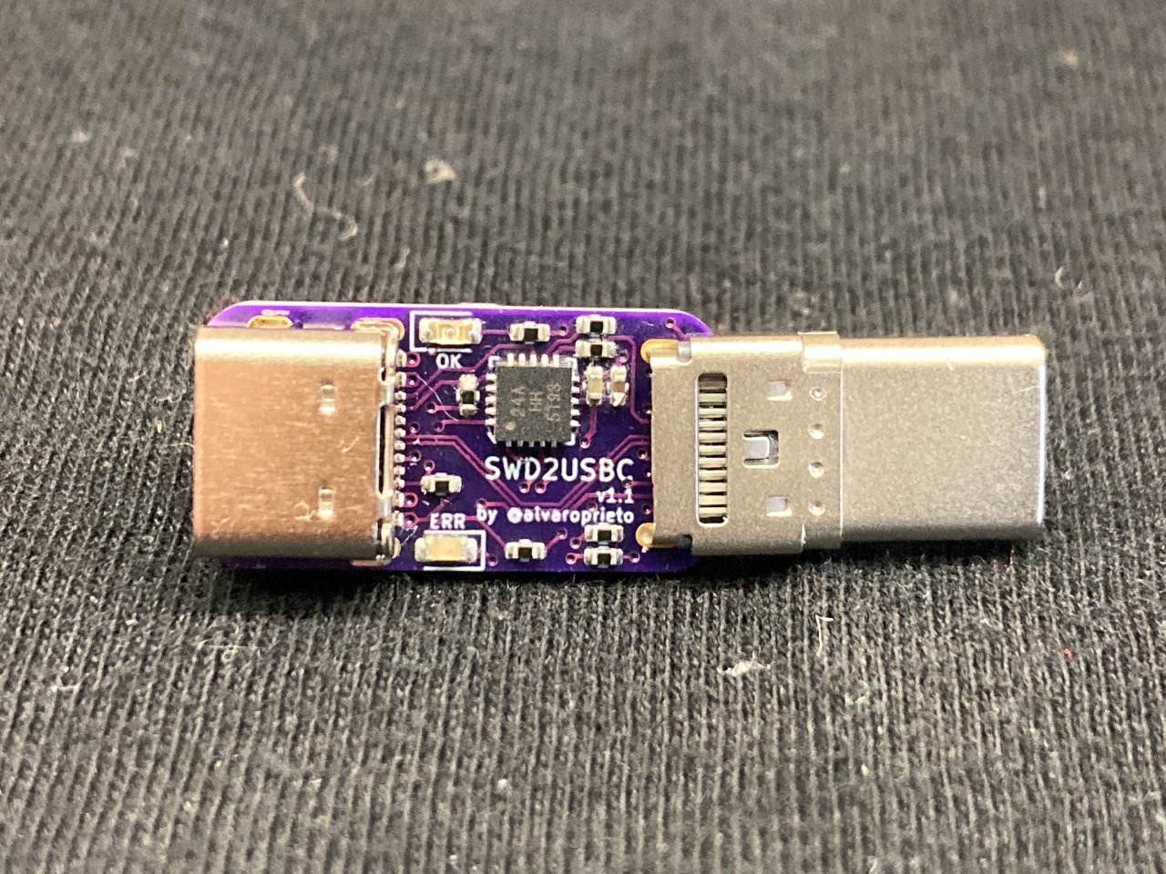
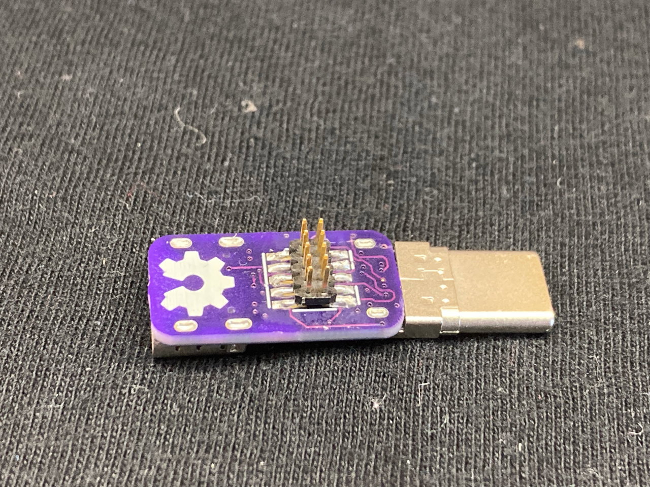
Have you ever wanted to debug your device over USB-C? Sometimes there's not enough room for a JTAG/SWD connector, or even TAGConnect pads! The USB-C specification has a Debug Accessory Mode feature that allows for this. I have a Twitter thread with additional details. Here's an unrolled version for easier reading.
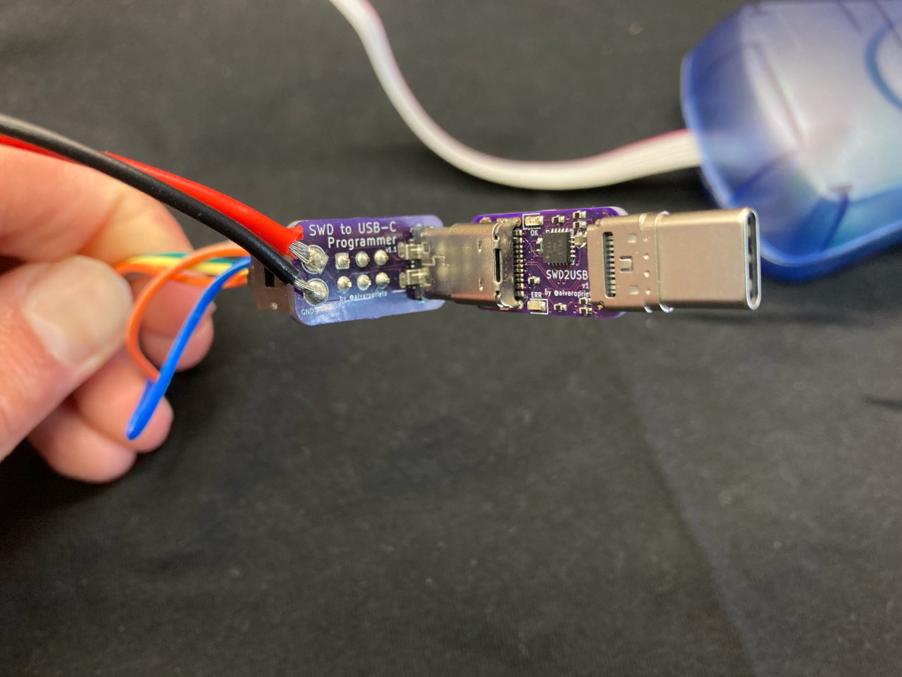
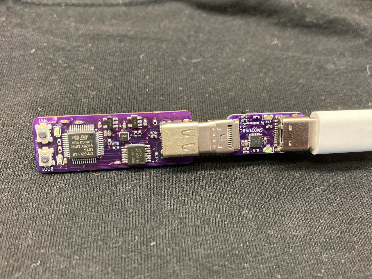
Since the current adapter uses an ATTiny24a, I made a different programmer adapter for it
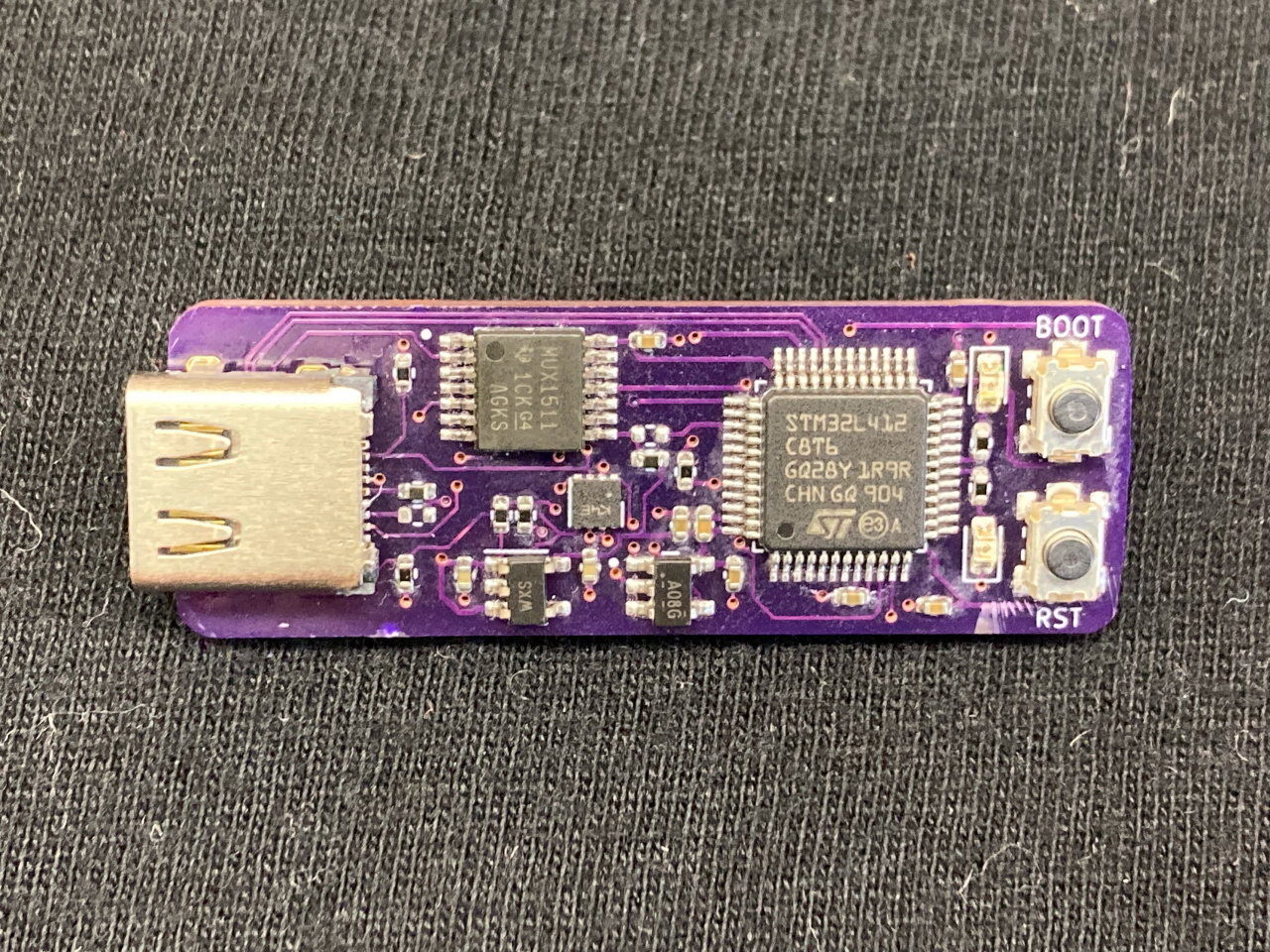
This is a simple STM32L4 board that implements USB-C DAM (the "proper way") as an example.
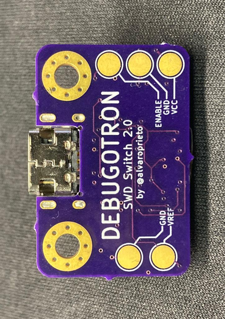
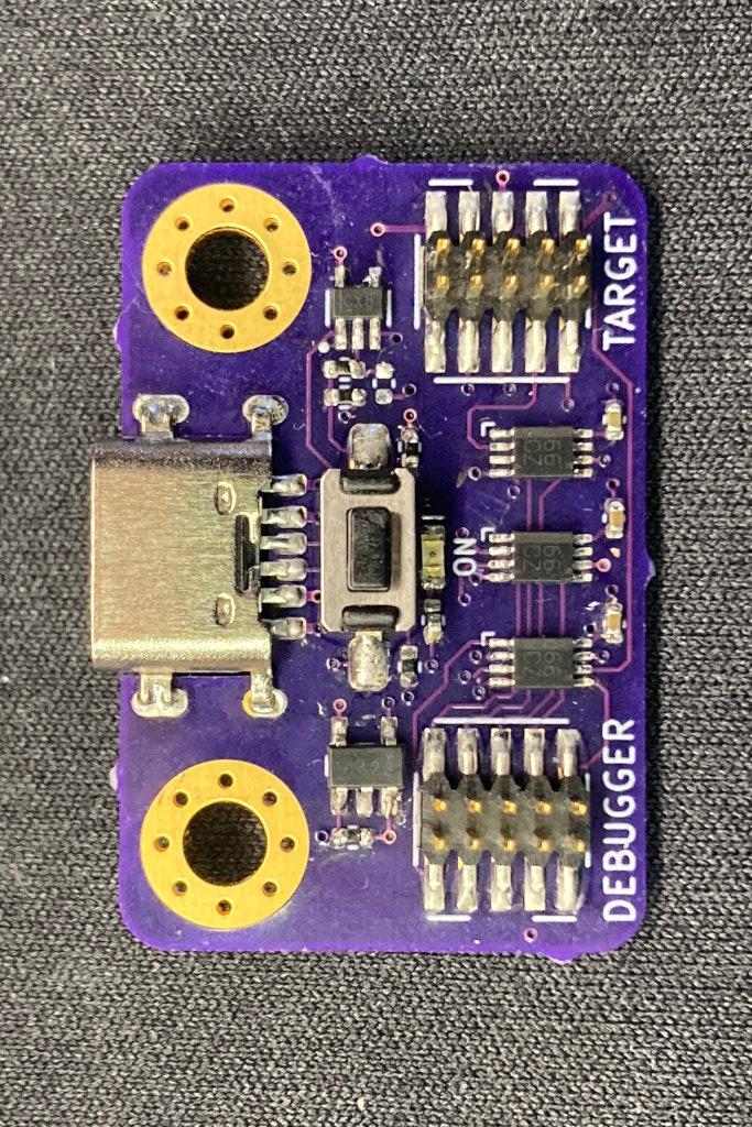
Tool that allows connecting/disconnecting the SWD/JTAG lines (Via ARM 10-pin connector) with a pushbutton (or external signal). This can be useful when trying to measure ultra low power consumption on a device while the debugger is connected (but not necessarily running/attached).
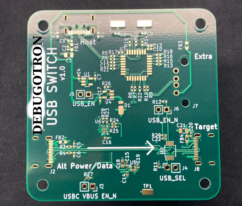
This one is more of an automation tool. I've always wanted to automate firmware testing. Sometimes, having USB connected is necessary to program/communicate with a device, but at the same time, having USB connected changes the power characteristics of the test (or just operating mode).
For example, you might want to automatically test the power consumption of a battery powered device every night with the latest firmware. In order to run the test, you might have to connect to the device, flash it, then disconnect USB. The USB-C switch will allow software-controlled power and data connect/disconnects to a USB-C device. Depending on the configuration, it will also allow full 20V@5A pass-through by allowing USB-PD communication over the CC lines.
In the cases where you want to communicate with a device over USB while still powering it via 20V (or anything higher than 5V), a USB switch allows for a different USB cable to be used for data only, while power is taken from a separate USB-C port.
| Qty | Value | Footprint | References |
|---|---|---|---|
| 10 | 1uF | Capacitor_SMD:C_0402_1005Metric | C4, C5, C6, C7, C10, C11, C14, C16, C17, C20 |
| 8 | 27 | Resistor_SMD:R_0402_1005Metric | R3, R4, R5, R6, R7, R8, R9, R10 |
| 7 | 0 | Resistor_SMD:R_0402_1005Metric | R13, R14, R15, R16, R18, R19, R22 |
| 7 | 10k | Resistor_SMD:R_0402_1005Metric | R11, R12, R21, R23, R26, R27, R28 |
| 5 | 0.1uF | Capacitor_SMD:C_0402_1005Metric | C2, C12, C13, C15, C22 |
| 4 | Conn_01x02 | Connector_PinSocket_2.54mm:PinSocket_1x02_P2.54mm_Vertical | J3, J4, J5, J6 |
| 4 | FerriteBead | Inductor_SMD:L_0603_1608Metric | FB1, FB2, FB3, FB4 |
| 2 | 1.5k | Resistor_SMD:R_0402_1005Metric | R17, R20 |
| 2 | 33pF | Capacitor_SMD:C_0402_1005Metric | C8, C9 |
| 2 | 5.1k | Resistor_SMD:R_0402_1005Metric | R1, R2 |
| 1 | 0.01uF | Capacitor_SMD:C_0402_1005Metric | C1 |
| 1 | 100 | Resistor_SMD:R_0402_1005Metric | R29 |
| 1 | 10uF | Capacitor_SMD:C_0603_1608Metric | C18 |
| 1 | 1M | Resistor_SMD:R_0402_1005Metric | R24 |
| 1 | 22uF | Capacitor_SMD:C_0805_2012Metric | C21 |
| 1 | 4.7uF | Capacitor_SMD:C_0805_2012Metric | C3 |
| 1 | 62k | Resistor_SMD:R_0402_1005Metric | R25 |
| 1 | 6MHz | Crystal:Crystal_SMD_HC49-SD | Y1 |
| 1 | AP22804AW5 | Package_TO_SOT_SMD:SOT-23-5 | U4 |
| 1 | C_Small | Capacitor_SMD:C_0402_1005Metric | C19 |
| 1 | D_Schottky | alvarop:CD123-B140LR | D1 |
| 1 | FSUSB30L10X | Package_SO:MSOP-10_3x3mm_P0.5mm | U2 |
| 1 | GND | alvarop:RCWCTE | TP1 |
| 1 | MIC5504-3.3YM5 | Package_TO_SOT_SMD:SOT-23-5 | U1 |
| 1 | NX20P5090 | alvarop:NX20P5090UK | U6 |
| 1 | SLG7NT402V | alvarop:FC-TDFN-8 | U5 |
| 1 | TUSB2036 | Package_QFP:LQFP-32_7x7mm_P0.8mm | U3 |
| 1 | alt_source_usb | alvarop:USB4105-GF-A | J2 |
| 1 | extra_usb | alvarop:UE27ACX410X | J7 |
| 1 | host_usb | alvarop:USB4105-GF-A | J1 |
| 1 | target_usb | alvarop:USB4105-GF-A | J8 |
The 72 most common of 77 parts.
It measures 60 × 60 mm and has 4 copper layers, 1.6 mm thick.
77 parts, built around the FSUSB30L10X, TUSB2036VF, AP22804AW5 and MIC5504-3.3YM5. The full list of its parts is on this page, with links to each part's symbol and footprint where PCBKit's library has them.
From the alvarop/debugotron repository on GitHub, at the commit this page was made from: the board is hw/usb_switch/usb_switch.kicad_pcb and its schematic hw/sample_target/sample_target.kicad_sch. PCBKit opens the board in the browser, with nothing to install.
Its repository publishes it under the BSD-3-Clause licence: you may reuse it on that licence's terms (keep the author's notice, and for a copyleft licence share your changes alike).
alvarop/debugotron
Debugotron is a collection of debugging/automation tools I've wanted in the past but didn't have access to. Currently, the tools include:

alvarop/debugotron
Debugotron is a collection of debugging/automation tools I've wanted in the past but didn't have access to. Currently, the tools include:

alvarop/debugotron
Debugotron is a collection of debugging/automation tools I've wanted in the past but didn't have access to. Currently, the tools include:


torlye/pocket-reform
My muscle memory requires me to have the Ctrl key at the bottom left corner of the keyboard!

dmanla/SecureConnectivityDevelopmentPlatform
A development platform which provides secure connectivity and data logging support while maintaining compatibility with Arduino-Mega hardware and software.


markusbichl/ADC_Silence_Detector
WCH CH32X033 based Silence detector for turntable to Toslink converter

si-nalsal/pcb-mantis
A servo-based UAV flight controller built around the STM32H743IIK6 (Cortex-M7, UFBGA-201, 0.65 mm pitch). The board distributes power to a fixed-wing/multirotor airframe with 16 PWM servo outputs, redundant IMU and…

XyrusB2010/XYmatics-E64
A 5-axis Klipper mainboard, powered by a Raspberry Pi Compute Module and STM32F407