4 layers60 × 60 mm
Usb switch
alvarop/debugotron
Debugotron is a collection of debugging/automation tools I've wanted in the past but didn't have access to. Currently, the tools include:
77 parts52BSD-3-Clause

 alvarop/debugotron52
Debugotron is a collection of debugging/automation tools I've wanted in the past but didn't have access to. Currently, the tools include:
Swd switch is an open-source printed circuit board by alvarop, from the alvarop/debugotron repository on GitHub, published under the BSD-3-Clause licence. It is a 4-layer board of 30 × 20 mm with 28 parts on 27 nets, routed with 276 tracks and 49 vias.
It is built around the SN74LVC2G66DCU, SN74AHC1G14DBVR and SN74AHC1G32DBVR, with the SN74LVC1G80DCKRE4, 20021121-00010C4LF and PTS636 SL43 SMTR LFS among its other parts. Its parts include 6 resistors, 6 ICs, 4 capacitors, 3 connectors and 1 diode. It belongs with the interfaces and adapters boards of this library.


Debugotron is a collection of debugging/automation tools I've wanted in the past but didn't have access to. Currently, the tools include:
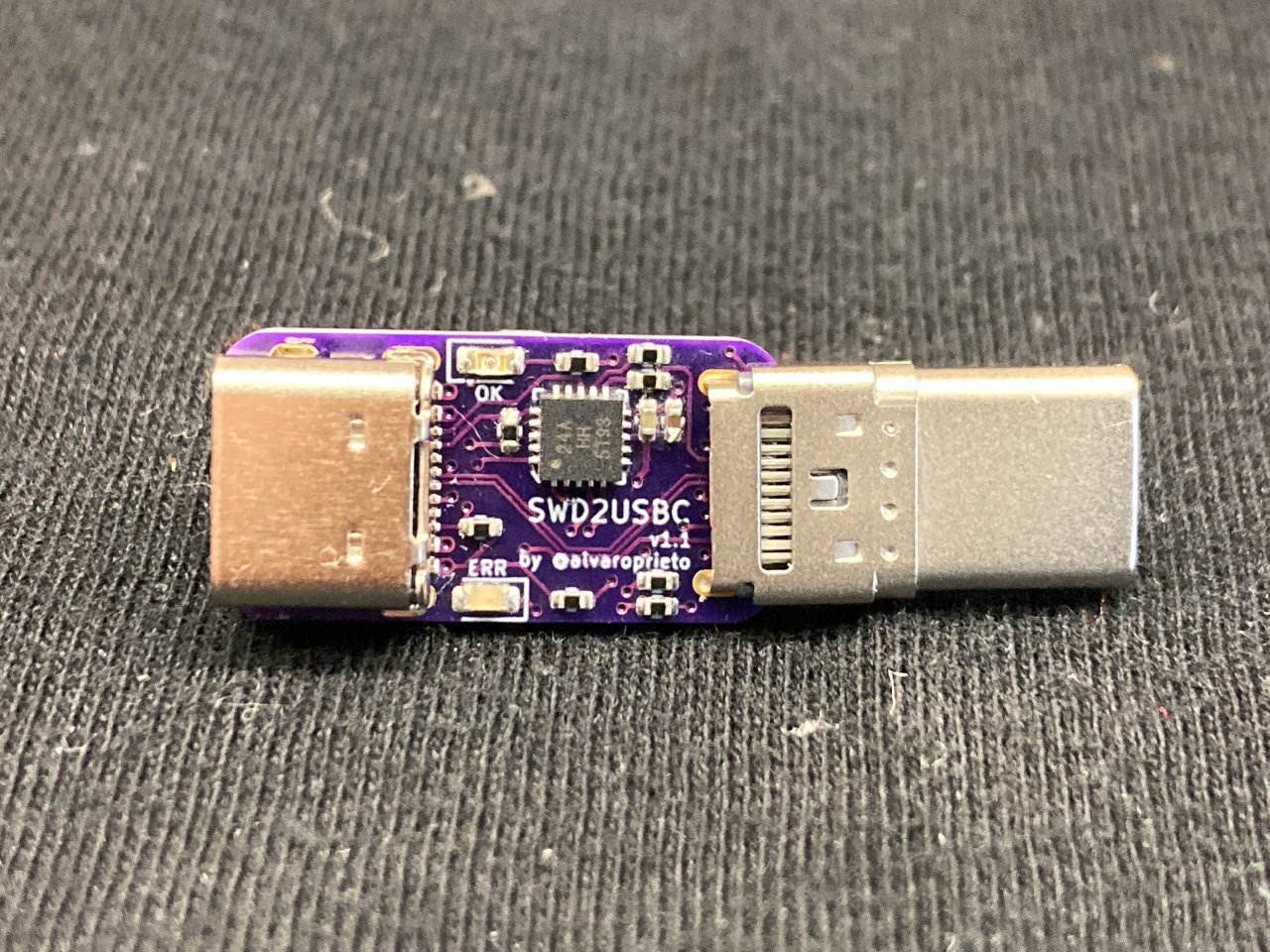
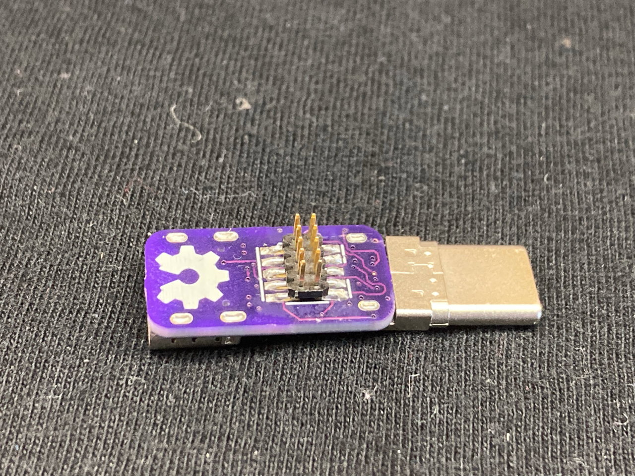
Have you ever wanted to debug your device over USB-C? Sometimes there's not enough room for a JTAG/SWD connector, or even TAGConnect pads! The USB-C specification has a Debug Accessory Mode feature that allows for this. I have a Twitter thread with additional details. Here's an unrolled version for easier reading.
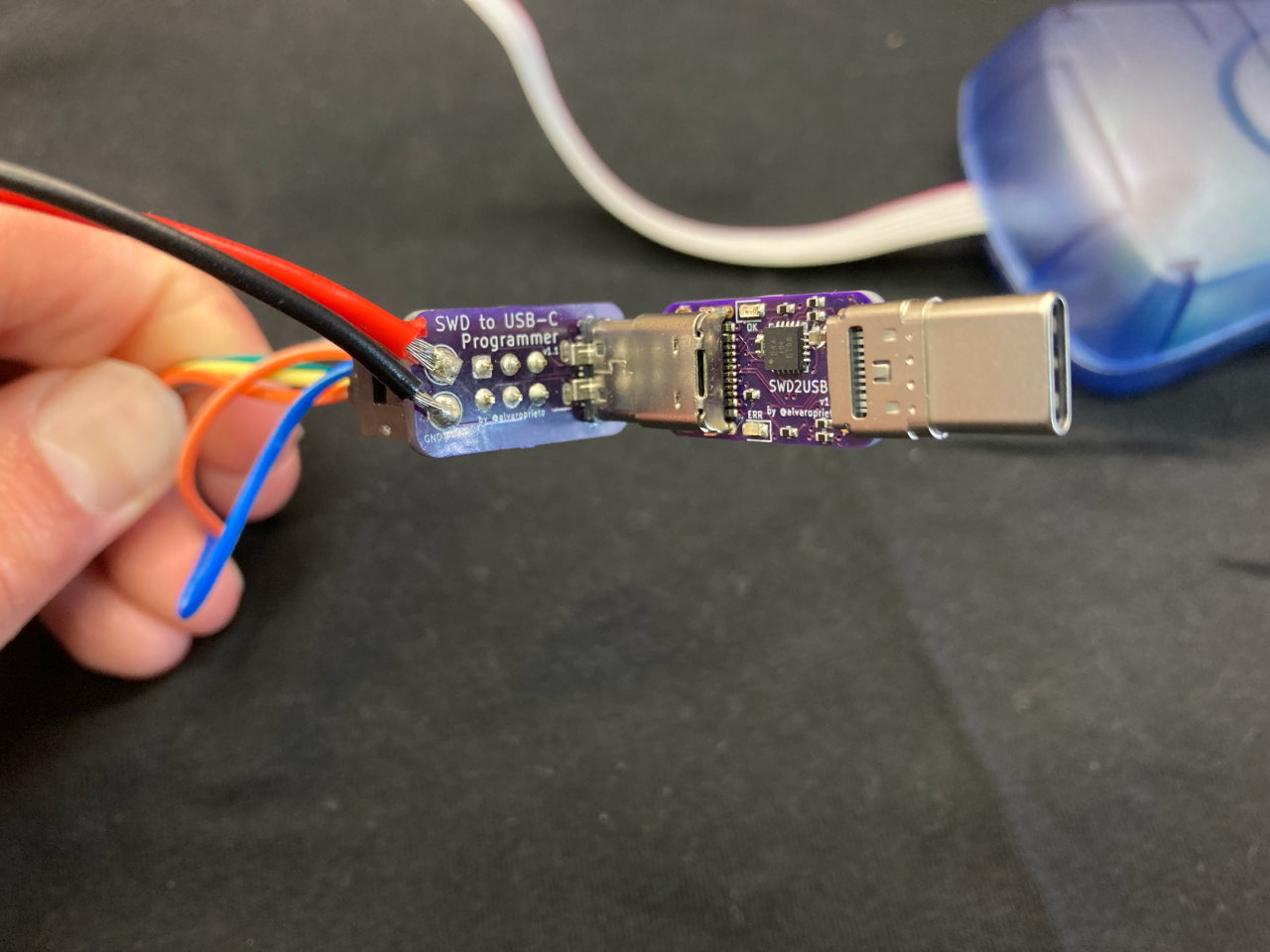
Since the current adapter uses an ATTiny24a, I made a different programmer adapter for it
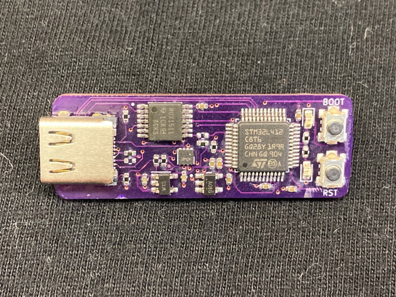
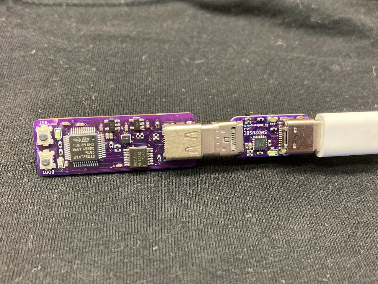
This is a simple STM32L4 board that implements USB-C DAM (the "proper way") as an example.
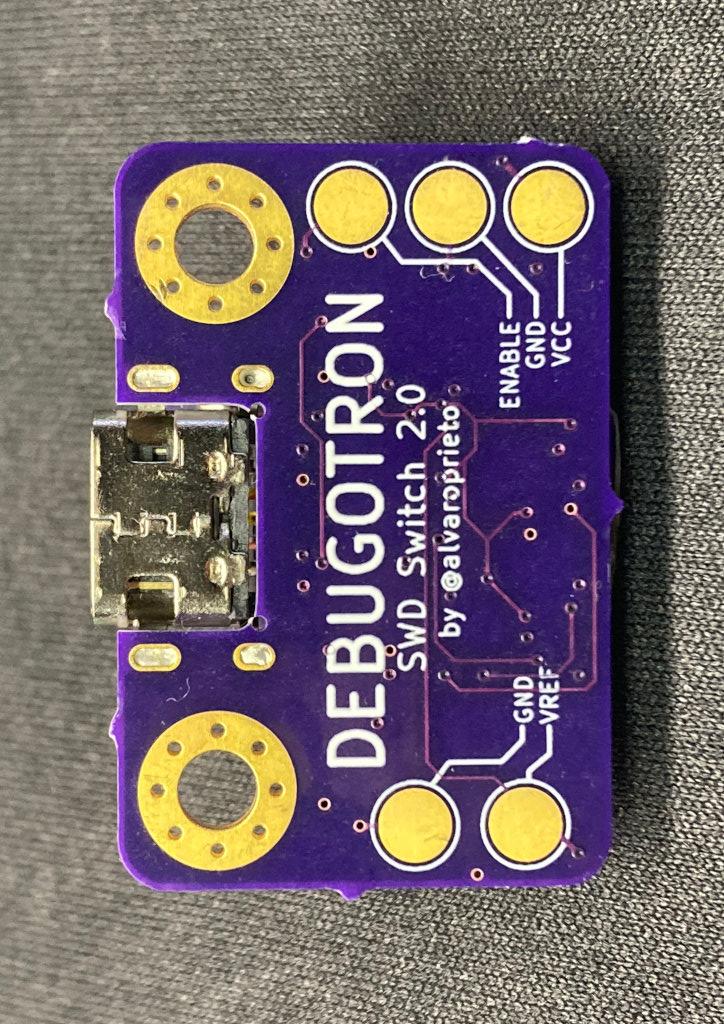
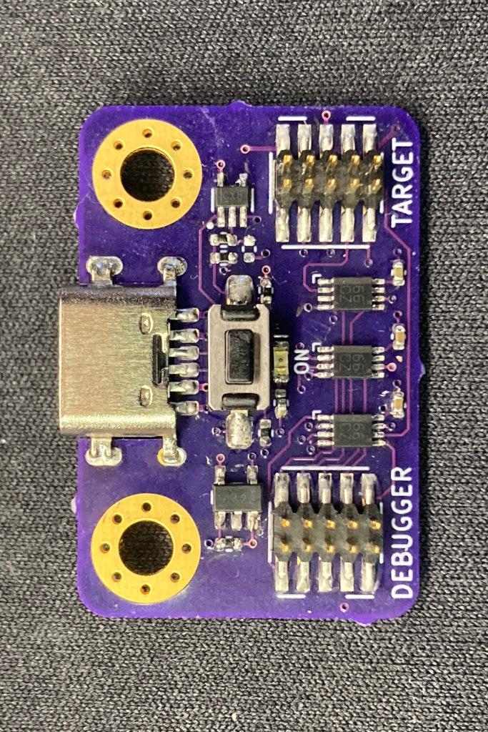
Tool that allows connecting/disconnecting the SWD/JTAG lines (Via ARM 10-pin connector) with a pushbutton (or external signal). This can be useful when trying to measure ultra low power consumption on a device while the debugger is connected (but not necessarily running/attached).
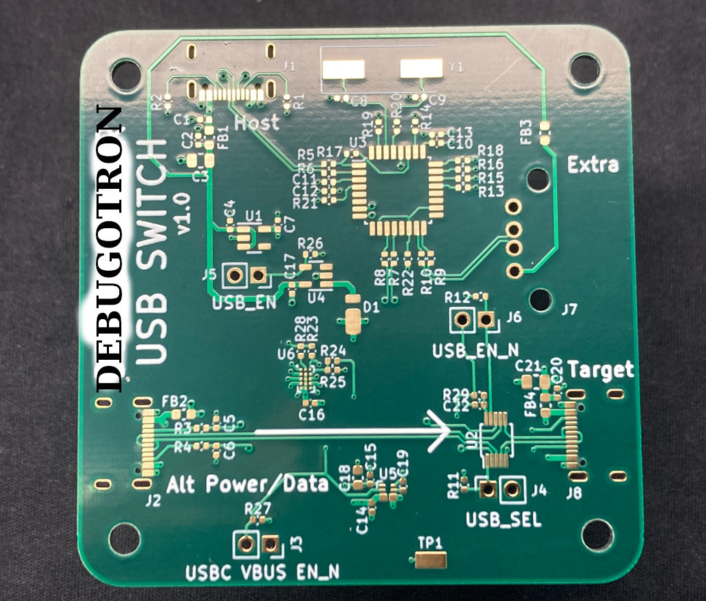
This one is more of an automation tool. I've always wanted to automate firmware testing. Sometimes, having USB connected is necessary to program/communicate with a device, but at the same time, having USB connected changes the power characteristics of the test (or just operating mode).
For example, you might want to automatically test the power consumption of a battery powered device every night with the latest firmware. In order to run the test, you might have to connect to the device, flash it, then disconnect USB. The USB-C switch will allow software-controlled power and data connect/disconnects to a USB-C device. Depending on the configuration, it will also allow full 20V@5A pass-through by allowing USB-PD communication over the CC lines.
In the cases where you want to communicate with a device over USB while still powering it via 20V (or anything higher than 5V), a USB switch allows for a different USB cable to be used for data only, while power is taken from a separate USB-C port.
| Qty | Value | Footprint | References |
|---|---|---|---|
| 6 | 5.1k | Resistor_SMD:R_0402_1005Metric | R1, R2, R3, R4, R5, R6 |
| 5 | TestPoint | TestPoint:TestPoint_Pad_D3.0mm | TP1, TP2, TP3, TP4, TP5 |
| 4 | 0.1uF | Capacitor_SMD:C_0402_1005Metric | C1, C2, C3, C4 |
| 3 | SN74LVC2G66 | alvarop:SN74LVC2G66-VSSOP | U3, U4, U5 |
| 1 | LED | LED_SMD:LED_0603_1608Metric | D1 |
| 1 | SN74AHC1G14 | Package_TO_SOT_SMD:SOT-23-5 | U6 |
| 1 | SN74LVC1G32DBVR | snapeda:SOT95P280X145-5N | U2 |
| 1 | SN74LVC1G80DCKR | snapeda:SOT65P210X110-5N | U1 |
| 1 | SWD_IN | snapeda:SAMTEC_FTSH-105-01-F-DV-P-TR_alt | J3 |
| 1 | SWD_OUT | snapeda:SAMTEC_FTSH-105-01-F-DV-P-TR_alt | J5 |
| 1 | SW_Push | alvarop:PTS636_G | SW1 |
| 1 | USB_C_Receptacle_USB2.0 | alvarop:USB4515-GF-A | J2 |
The 26 most common of 28 parts.
It measures 30 × 20 mm and has 4 copper layers, 0.8 mm thick.
28 parts, built around the SN74LVC2G66DCU, SN74AHC1G14DBVR, SN74AHC1G32DBVR and SN74LVC1G80DCKRE4. The full list of its parts is on this page, with links to each part's symbol and footprint where PCBKit's library has them.
From the alvarop/debugotron repository on GitHub, at the commit this page was made from: the board is hw/swd_switch/swd_switch.kicad_pcb and its schematic hw/sample_target/sample_target.kicad_sch. PCBKit opens the board in the browser, with nothing to install.
Its repository publishes it under the BSD-3-Clause licence: you may reuse it on that licence's terms (keep the author's notice, and for a copyleft licence share your changes alike).
alvarop/debugotron
Debugotron is a collection of debugging/automation tools I've wanted in the past but didn't have access to. Currently, the tools include:

alvarop/debugotron
Debugotron is a collection of debugging/automation tools I've wanted in the past but didn't have access to. Currently, the tools include:

alvarop/debugotron
Debugotron is a collection of debugging/automation tools I've wanted in the past but didn't have access to. Currently, the tools include:


rapha-tech/ESP32-hema-console
New PCB for the small console from hema to use an ESP32


mickdassive/boulder_clock_replacent_bord
This project provides the source code and design files for the Boulder Clock Replacement Board, designed as a direct drop-in replacement for the original Boulder Clock hardware.

ywhs05/DigitalToFiberOpticConverter-PCB
Circuito que recibe señales digitales y las convierte a fibra óptica.
