4 layers53 × 35.2 mm

 alex31/smartprobe1
firmware and hardware for an autonomous five holes 3D pitot tube
SmartProbe v004 is an open-source printed circuit board by alex31, from the alex31/smartprobe repository on GitHub. It is a 4-layer board of 84.5 × 17 mm with 90 parts on 112 nets, routed with 915 tracks and 237 vias.
It is built around the STM32F777VIH6, LPS33HW and SDP31, with the LP5912-3.3DRVR, ICM-20600 and MAX3051EKA among its other parts. Its parts include 36 capacitors, 22 resistors, 10 ICs, 8 diodes and 3 connectors. It belongs with the STM32 boards of this library.


Smartprobe is an autonomous pitot3d tube that is designed to be mounted on a drone. It records relative wind speed and angles, stores them on sdcard, and stream data on a serial line.
use the latest binary found under GitHub Releases
cross compilation and Perl library for the boardGen.pl tool :
sudo apt install build-essential gcc-arm-none-eabi gdb-multiarch \
         default-jre libmodern-perl-Perl \
	 libxml-libxml-Perl libfile-which-Perl \
	 dfu-util

sudo cpan -i String/LCSS.pm
to use bmpflash when flashing with a Black Magic Probe or Criquet Probe
sudo usermod -a -G dialout $USERhttps://www.st.com/en/development-tools/stm32cubemx.html (boardGen.pl script needs xml MCU description files) If stm32cubemx is not found, a pregenerated board.h is used, you won't be able to modify pin assignation
git clone --recursive https://github.com/alex31/smartprobe.git
cd smartprobe
git submodule update --init --recursivemake clean; make BUILD=SIZEIn dfu mode : plug micro-USB cable (no need to power supply)
make BUILD=SIZE dfuflashIn swd mode : plug swd cable (need to power supply smartprobe)
make BUILD=SIZE flashIt is mandatory to install a micro sd card :
The Molex connector at the back contains :
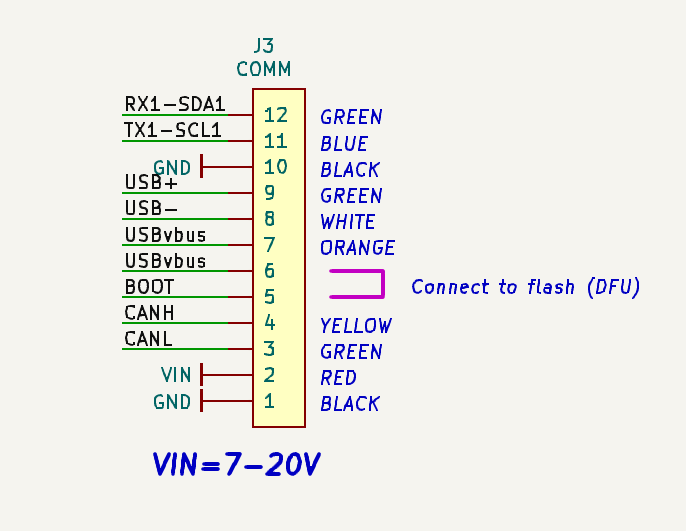
| Parameter | Description | default |
|---|---|---|
| syslog.filename | name of the file where system events are logged | syslog |
| sensorslog.filename | name of the file where sensors data are logged | sensors |
| thread.frequency.d_press | differential pressure sampling frequency | 100 |
| thread.frequency.imu | IMU sampling frequency | 100 |
| thread.frequency.stream_console | frequency of messages on the console | 10 |
| thread.frequency.transmit_uart | frequency of messages on serial link | 100 |
| ahrs.type | type of AHRS : raw, headless, or complete | headless_ahrs |
| ahrs.output | ahrs output format : euler or quaternion | euler |
| uart.mode | no_used or pprz or nmea_in or ubx_in | pprz |
| pprz.message | pprz msg to stream data : aeroprobe or smartprobe | aeroprobe |
| uart.baud | Baud rate of the uart in the range 9600..460800 | 115200 |
| canbus.mode | not yet implemented | |
| canbus.id | not yet implemented | |
| sensor.barometer.temperatureBias | temperature bias of the measured exterior air | -5 |
| sensor.barometer.lpf | barometer clock divider (see LPS33HW datasheet) | div2 |
| sensor.barometer.odr | barometer output data rate (see LPS33HW datasheet) | 50hz |
| sensor.d_press.fetched | diff pressure param fetched : press or press + temp | P+T |
| sensor.d_press.fetchTempFrequency | diff pressure temp frequency fetching | 1<< |
| sensor.imu.accrate | imu acc fetching rate (see ICM20600 datasheet) | 1khz_bw99 |
| sensor.imu.gyrorange | gyro range [250 .. 2000] degrees per seconds | 250_dps |
| sensor.imu.accrange | acc range [2 .. 16] G | 2g |
| sensor.imu.estimationLoopDuration_ms | ahrs calibration duration [10 .. 4000] milliseconds | 500 |
| airspeed.rho | estimated (0) or fixed in the range [0.1 .. 2] | 0(force estimation) |
| airspeed.calibration.m11 | transformation matrix from the | 1.15 |
| airspeed.calibration.m12 | calibration process | 0 |
| airspeed.calibration.m13 | default values can be used to verify that | 0 |
| airspeed.calibration.m14 | the smartprobe roughly works, but should not be | 6 |
| airspeed.calibration.m15 | used to make actual measures | 6 |
| airspeed.calibration.m21 | 0 | |
| airspeed.calibration.m22 | 15 | |
| airspeed.calibration.m23 | 0 | |
| airspeed.calibration.m24 | 0 | |
| airspeed.calibration.m25 | 0 | |
| airspeed.calibration.m31 | 0 | |
| airspeed.calibration.m32 | 0 | |
| airspeed.calibration.m33 | 11 | |
| airspeed.calibration.m34 | 0 | |
| airspeed.calibration.m35 | 0 | |
| airspeed.calibration.bias.velocity | bias on air velocity (from calibration) | 0 |
| airspeed.calibration.bias.alpha | bias on alfa angle (from calibration) | 0 |
| airspeed.calibration.bias.beta | bias on beta angle (from calibration) | 0 |
| led.mode | status or airspeed | status |
Smartprobe should be calibrated in a wind tunnel before use. The calibration matrix values should then be written in the configuration file instead of the default values.
...TO BE WRITTEN...
there is a SWD connector on the PCB for connecting a debug probe (Black Magic Probe or STlink V2/V3) which permits debugging with gdb and access to a shell console where errors messages are shown.
The led color reflect status of operation (see details below). When error occurs, the error details are logged in the syslog file, on the sdcard, and on debug console if a probe is attached to the internal swd+serial connector.
..
| Qty | Value | Footprint | References |
|---|---|---|---|
| 17 | 100nF | _Capacitors_GRZ:C_0402 | C7, C8, C10, C11, C12, C13, C14, C15, C16, C17, C18, C19, C20, C21, C22, C23 +1 |
| 11 | 2.2kΩ | _Resistors_GRZ:R_0402 | R8, R9, R10, R11, R12, R13, R14, R15, R16, R17, R18 |
| 6 | 10µF | _Capacitors_GRZ:C_0603 | C29, C30, C31, C32, C33, C34 |
| 5 | PMEG3010AESB | _Diodes_GRZ:PMEG3010AESB | D1, D2, D3, D4, D5 |
| 3 | 4.7µF | _Capacitors_GRZ:C_0402 | C26, C27, C28 |
| 3 | SDP31 | _Sensors_GRZ:SDP31 | IC5, IC6, IC7 |
| 2 | 1.5kΩ | _Resistors_GRZ:R_0402 | R6, R7 |
| 2 | 10nF | _Capacitors_GRZ:C_0402 | C5, C6 |
| 2 | 18pF | _Capacitors_GRZ:C_0402 | C3, C4 |
| 2 | 1µF | _Capacitors_GRZ:C_0402 | C24, C25 |
| 2 | 390Ω | _Resistors_GRZ:R_0402 | R3, R4 |
| 2 | 4.7pF | _Capacitors_GRZ:C_0402 | C1, C2 |
| 2 | LP5912-3.3DRV | _Regulators_GRZ:LP5912DRV | IC1, IC2 |
| 1 | 0Ω | _Resistors_GRZ:R_0402 | R1 |
| 1 | 1.2kΩ | _Resistors_GRZ:R_0402 | R5 |
| 1 | 1000µF/6.3V | _Capacitors_GRZ:EIA_7360-38 | C36 |
| 1 | 100µF/20V | _Capacitors_GRZ:EIA_7343-31 | C35 |
| 1 | 10kΩ | _Resistors_GRZ:R_0402 | R20 |
| 1 | 10µH | _Inductors_GRZ:VLCF4020T | L1 |
| 1 | 120Ω | _Resistors_GRZ:R_0402 | R2 |
| 1 | 12kΩ | _Resistors_GRZ:R_0402 | R21 |
| 1 | 16MHz | _Misc_GRZ:Crystal_8Z | Q1 |
| 1 | 2.7kΩ | _Resistors_GRZ:R_0402 | R19 |
| 1 | 32.768KHz-9pF | _Misc_GRZ:Crystal_FC-135 | Q2 |
| 1 | 33kΩ | _Resistors_GRZ:R_0402 | R22 |
| 1 | COMM | _Connectors_GRZ:PicoBlade_53048-1210 | J3 |
| 1 | DEBUG | _Connectors_GRZ:PicoBlade_53261-0771 | J2 |
| 1 | ICM-20600 | _Sensors_GRZ:ICM-20600 | IC8 |
| 1 | KP-1608CGCK | _Opto_GRZ:KP-1608CGCK | LED2 |
| 1 | KP-1608SURC | _Opto_GRZ:KP-1608SURC | LED1 |
| 1 | LOGO | _Logos_GRZ:PaparazziPenguin_10x10 | G*** |
| 1 | LPS33HW | _Sensors_GRZ:LPS33HW | IC4 |
| 1 | LT1616 | _Regulators_GRZ:LT1616 | IC10 |
| 1 | MAX3051EKA | _IC_Misc_GRZ:MAX3051EKA | IC9 |
| 1 | MicroSD_Connector_500901-0801 | _Connectors_GRZ:MicroSD_500901-0801 | J1 |
| 1 | SK6812-SIDE-A | _Opto_GRZ:SK6812-SIDE-A | LED3 |
| 1 | STM32F777VI | _MCU_GRZ:STM32F777VI | IC3 |
The 83 most common of 90 parts.
It measures 84.5 × 17 mm and has 4 copper layers, 1.6 mm thick.
90 parts, built around the STM32F777VIH6, LPS33HW, SDP31 and LP5912-3.3DRVR. The full list of its parts is on this page, with links to each part's symbol and footprint where PCBKit's library has them.
From the alex31/smartprobe repository on GitHub, at the commit this page was made from: the board is hardware/Electronics/source/SmartProbe_v004.kicad_pcb and its schematic hardware/Electronics/source/SmartProbe_v004.kicad_sch. PCBKit opens the board in the browser, with nothing to install.
Its repository states no licence, so its author keeps all rights: ask alex31 before reusing the design.


AEFeinstein/Super-2023-Swadge-HW
Swadge devkit for an ESP32-S2 with all the bells and whistles


