4 layers78 × 89 mm

 alex1klimovich/nrf52840-macro-controller1
Custom nRF52840 productivity controller for digital artists — PCB, BLE/USB firmware, OLED, haptics, RGB, and enclosure CAD.
MacroController is an open-source printed circuit board by alex1klimovich, from the alex1klimovich/nrf52840-macro-controller repository on GitHub. It is a 2-layer board of 96 × 74 mm with 78 parts on 97 nets, routed with 460 tracks and 90 vias.
It is built around the MDBT50Q-1MV2, DRV2605LDGS and MT3608, with the TP4056-42-ESOP8, 1N4148WT and SK6812MINI-E among its other parts. Its parts include 19 diodes, 14 capacitors, 14 resistors, 13 switches and 4 ICs. It belongs with the radio and wireless and lEDs and displays boards and the nRF52 and nRF5x boards of this library.


A custom wireless/wired productivity controller designed for digital artists who repeatedly use keyboard shortcuts, brush controls, tool switching, and other workflow actions.
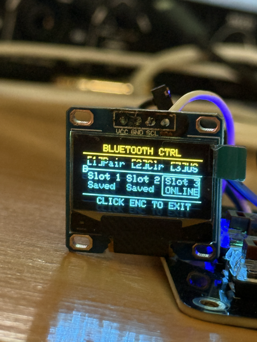
I designed the PCB, wrote the firmware, brought up the first board, and modeled the enclosure. The current prototype combines an nRF52840 module, eight hot-swap mechanical keys, a rotary encoder, OLED interface, per-key RGB, haptic feedback, battery monitoring, and USB/Bluetooth HID.
The goal is to make frequently used creative controls accessible through a compact physical interface that can be customized for different applications and workflows.
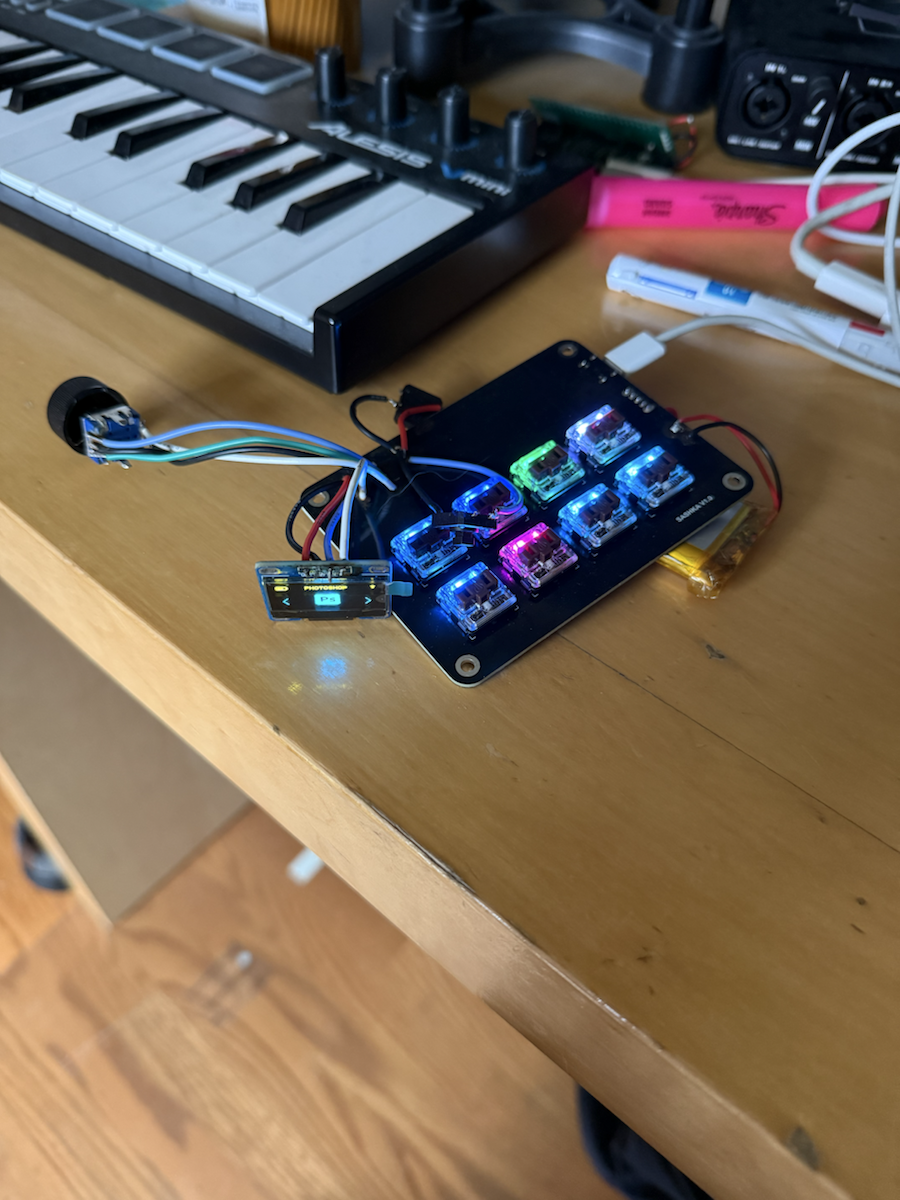
The controller was designed around the workflow of digital artists rather than as a generic macro pad.
Creative applications often require repeated keyboard shortcuts and parameter adjustments while the user's other hand remains focused on a mouse, stylus, or drawing tablet. The controller provides a compact set of tactile, programmable inputs intended to reduce those repetitive interactions.
The rotary encoder is suited to continuously adjusted parameters such as brush size, zoom, timeline position, or other application-specific controls. The mechanical keys can be assigned to frequently used tools, shortcuts, and multi-step actions.
Multiple profiles and three remembered Bluetooth hosts allow the same hardware to adapt to different applications and devices without rebuilding the firmware for each workflow.
The current prototype is being evaluated by an animation student at San José State University as an early real-world user.
Testing is focused on:
Feedback from this testing is being used to guide revisions to the control layout, enclosure, and software configuration experience. This is an ongoing prototype rather than a finished commercial product; the purpose of the testing stage is to identify usability problems before another hardware revision.
firmware/NRFMacroController/site.htmlflowchart LR
A["2×4 key matrix"] --> I["InputEngine"]
B["Encoder + side buttons"] --> I
I --> Q["RTOS event queue"]
Q --> S["StateManager"]
S --> F["LittleFS profiles + settings"]
Q --> O["OutputEngine"]
O --> U["USB HID"]
O --> L["BLE HID"]
O --> H["DRV2605L haptics"]
S --> D["OLED + RGB UI"]
C["Browser configurator"] <--> SThe PCB is built around a Raytac MDBT50Q nRF52840 module and includes:
The schematic below is exported from the checked-in KiCad source. It shows the Raytac MDBT50Q nRF52840 module, USB interface, battery charging and protection, haptic driver, key matrix, RGB LEDs, OLED I²C interface, rotary encoder, and side buttons.
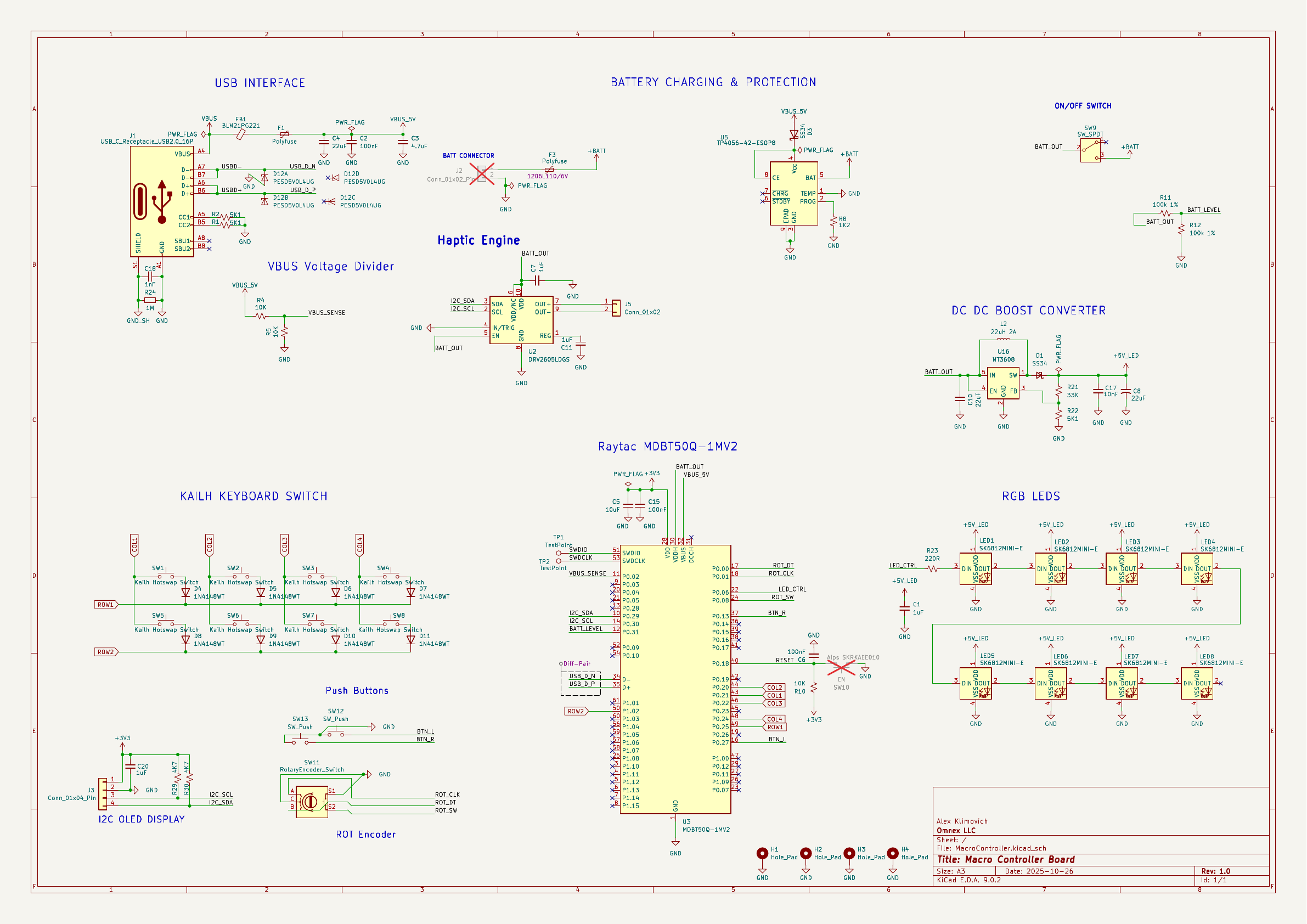
The original project directory retained an older ESP32_MCU-KEYBOARD_1.0 filename, but the current electrical design is the nRF52840 board shown above. The repository uses the clearer MacroController filenames for the editable KiCad sources.
The firmware separates input scanning, persistent state, output routing, and UI work. Input events move through an RTOS queue, while the state manager owns profiles and settings and the output engine handles HID, BLE, and haptic behavior.
Implemented behavior includes:
The checked-in firmware was compiled with Arduino CLI, Seeed nRF52 core 1.1.12, and the xiaonRF52840 target used by this project. The installed variant needs the low-frequency crystal selection supplied explicitly:
arduino-cli compile \
  --fqbn Seeeduino:nrf52:xiaonRF52840 \
  --build-property 'compiler.c.extra_flags=-DUSE_LFXO' \
  --build-property 'compiler.cpp.extra_flags=-DUSE_LFXO' \
  firmware/NRFMacroController
Verified build: 223,536 bytes of flash (27%) and 21,572 bytes of RAM (9%).
Required Arduino libraries include Adafruit TinyUSB, Adafruit Bluefruit nRF52, Adafruit GFX, Adafruit SSD1306, Adafruit NeoPixel, Adafruit DRV2605, ArduinoJson, and RotaryEncoder.
The repository includes editable KiCad schematic and board sources as well as the fabrication package used for the prototype: Gerbers, BOM, and component placement data.
| Current nRF52840 top assembly | Current nRF52840 bottom assembly |
|---|---|
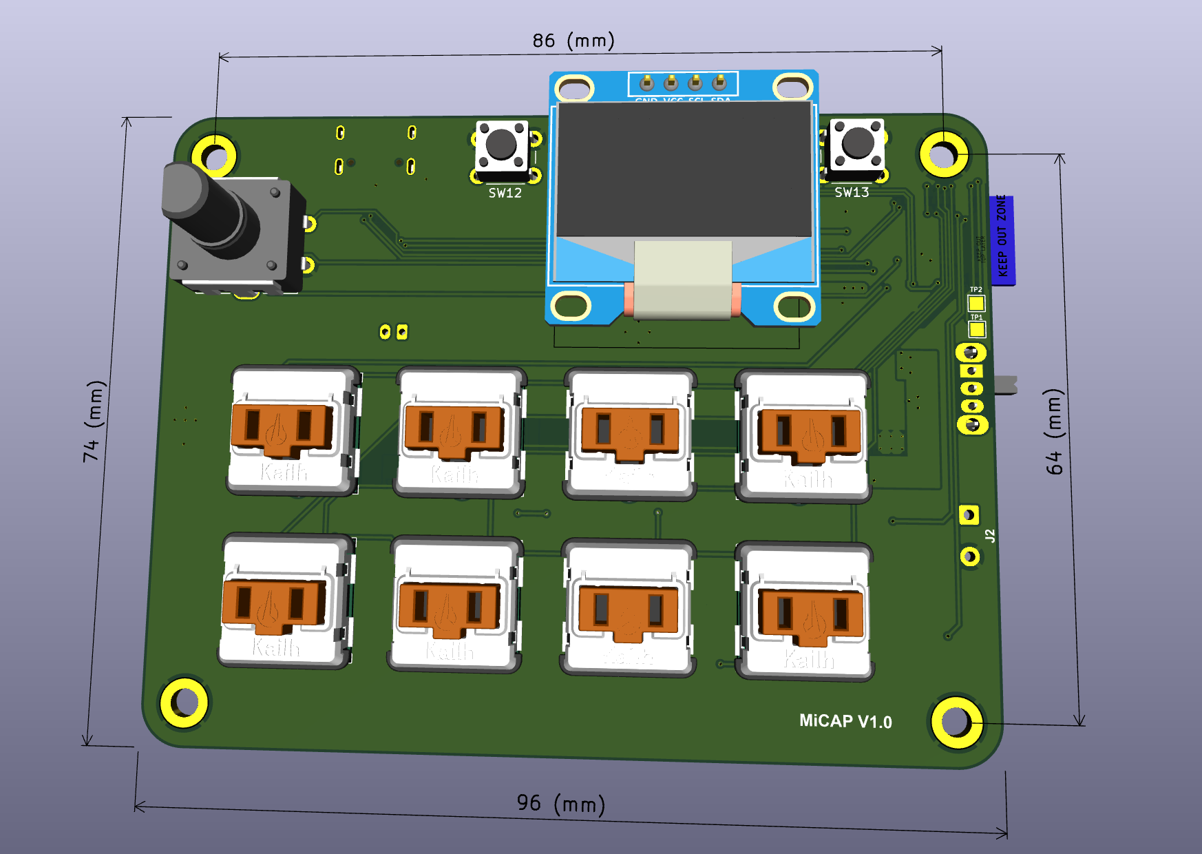 | 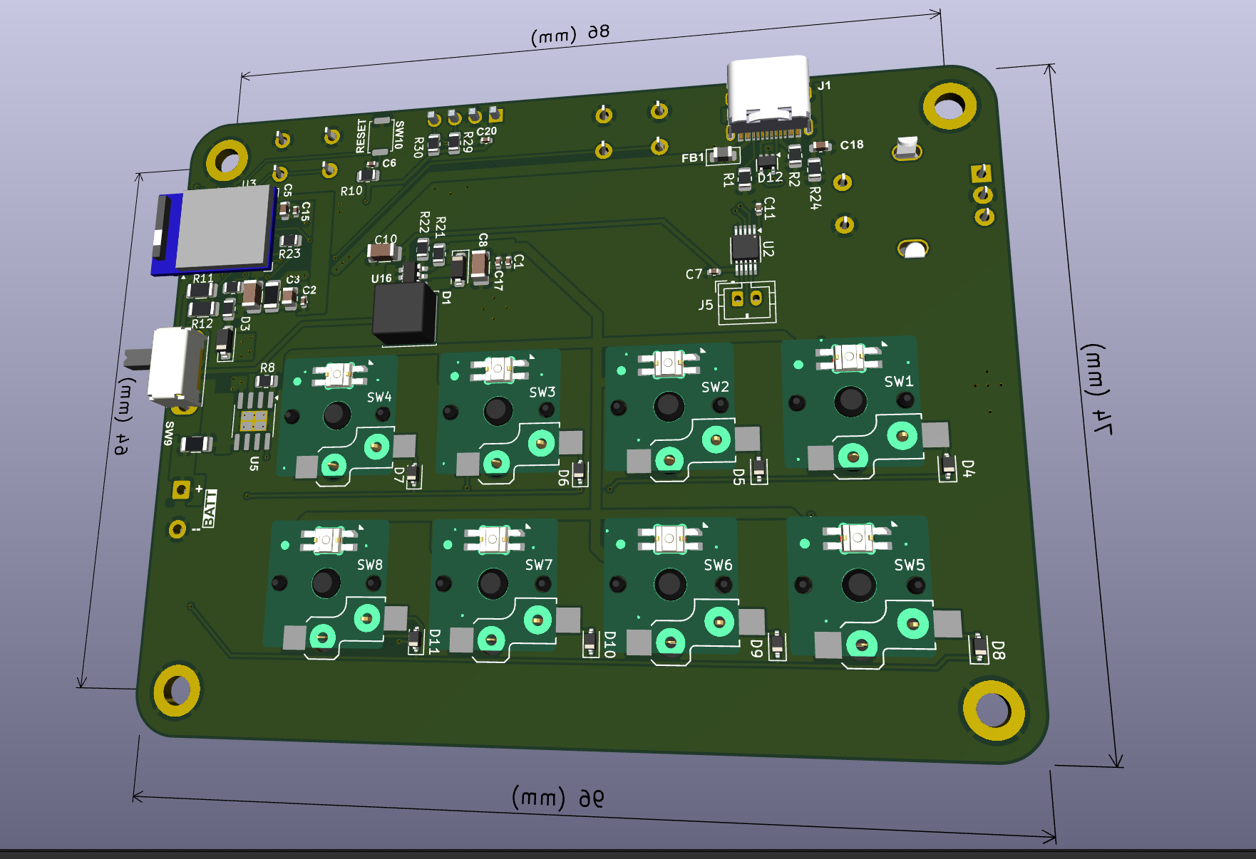 |
| Front copper and placement | Back copper and placement |
|---|---|
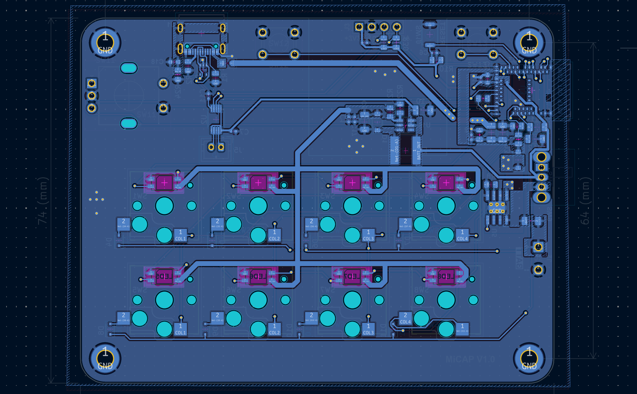 | 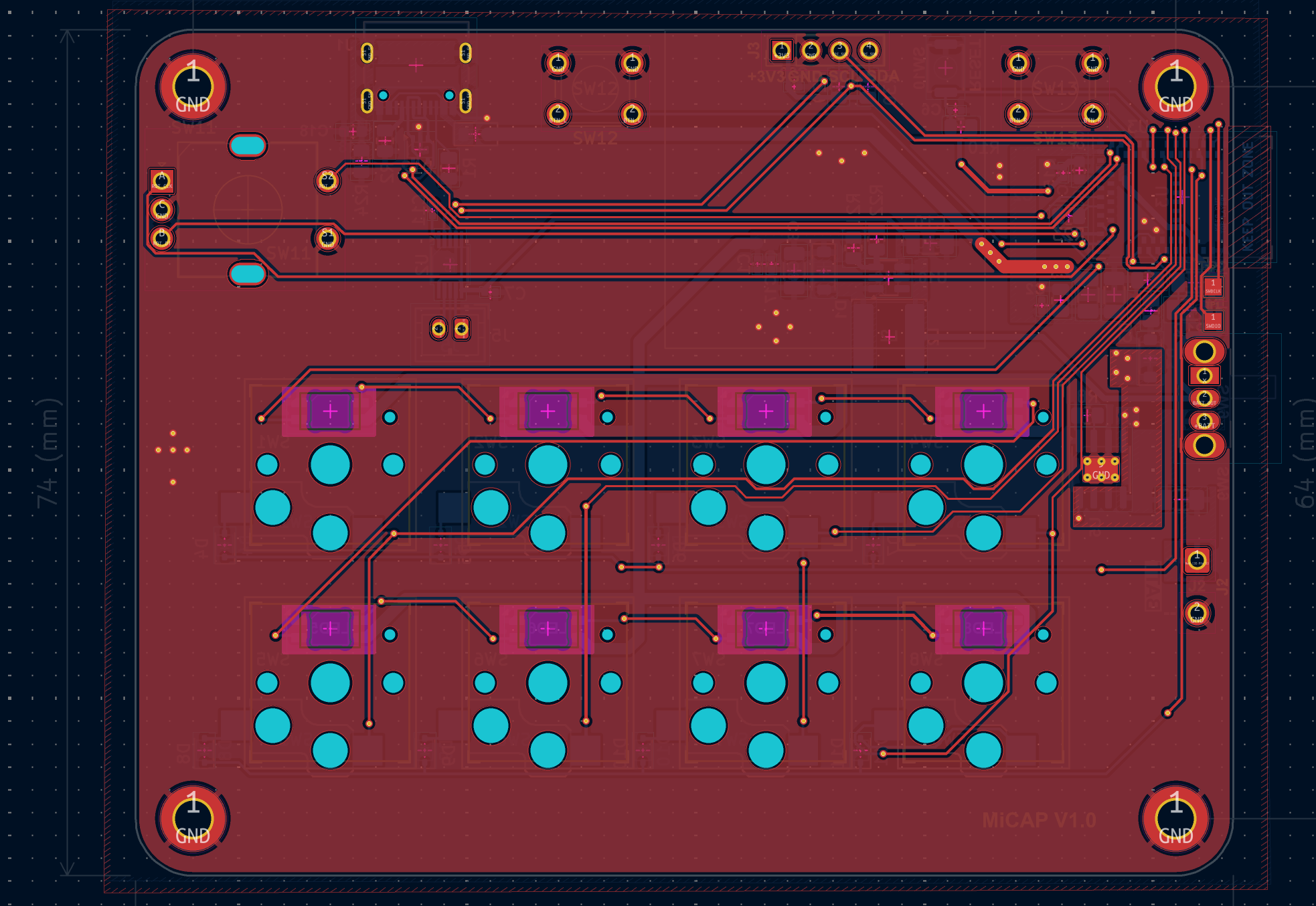 |
Before ordering another revision, KiCad ERC/DRC should be rerun and the generated manufacturing files reviewed against the selected component revisions. A historical DRC report was intentionally omitted because it predates the latest board edit and is not evidence of the current design state.
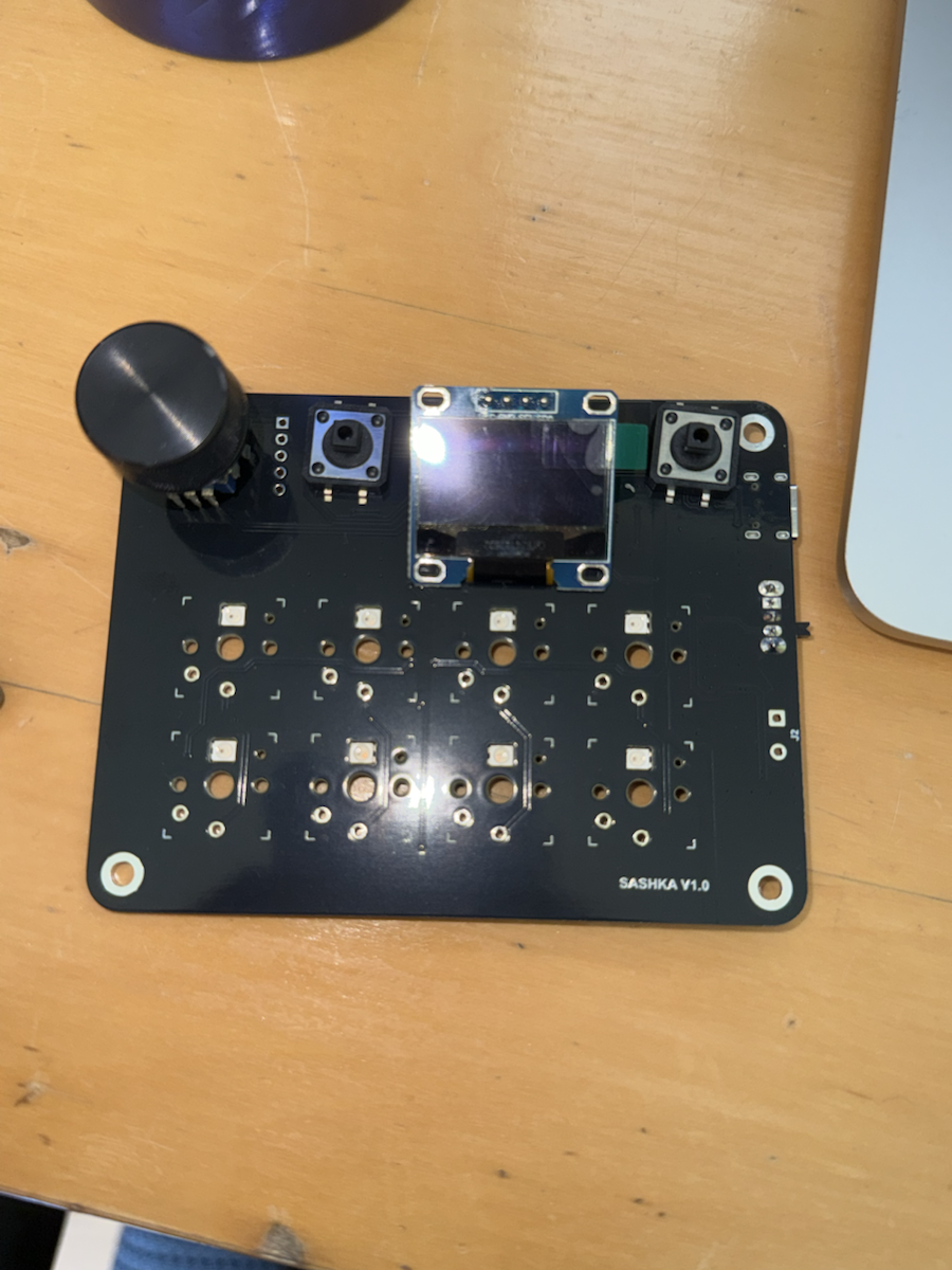
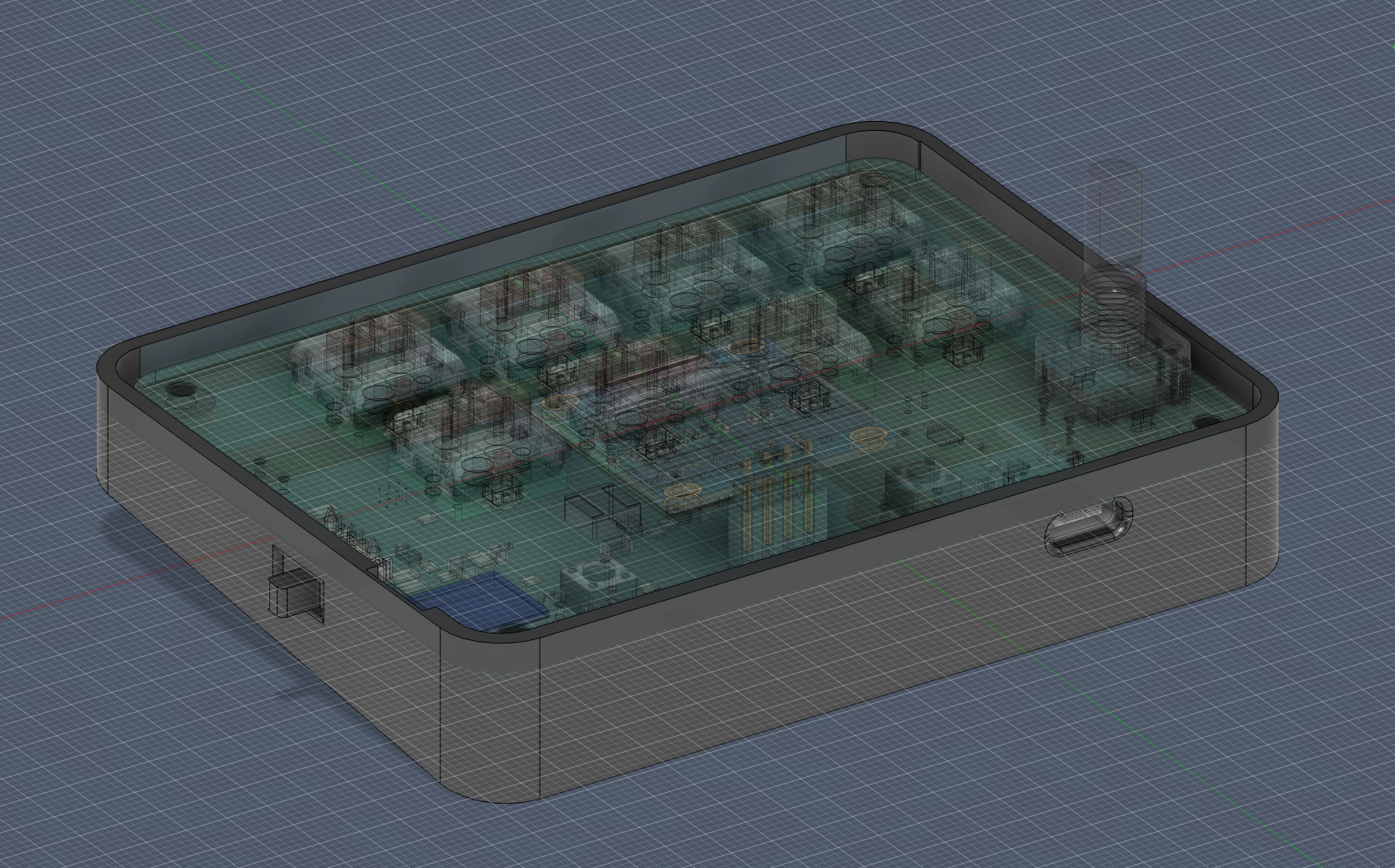
The mechanical folder contains the Blender enclosure model and STEP assembly developed around the PCB, switches, encoder, display, and connector access. The photographed unit is an exposed functional prototype; the current enclosure CAD has not yet been integrated into the pictured test unit.
The custom board did not initially produce the expected MCU response during bring-up. Debugging required revisiting both the programming assumptions and the boundary between the board design and its firmware/toolchain configuration.
The recovery process included:
That process led to successful firmware execution on the custom board and informed the explicit pin map and build configuration now documented in the repository.
The photographed board is a functional exposed prototype. Input scanning, OLED UI, LEDs, haptics, USB/BLE routing, persistent profiles, and device switching are implemented in the published firmware.
Current work is focused on findings from digital-art workflow testing, enclosure integration, and a simpler configuration experience. I have not recorded a workflow video yet, so the repository shows the hardware, source, and verified build without presenting a staged demo as completed testing.
| Path | Contents |
|---|---|
firmware/ | nRF52840 Arduino firmware and browser configurator |
hardware/kicad/ | KiCad schematic, PCB, local footprints, and board STEP export |
hardware/production/ | Fabrication Gerbers, BOM, and component placement file |
mechanical/ | Blender enclosure model and STEP assembly |
docs/images/ | Prototype photos, current nRF52840 schematic preview, PCB views, and enclosure CAD |
docs/schematics/ | Readable PDF export of the current nRF52840 schematic |
This is a personal hardware project. No license is granted for commercial manufacture or redistribution.
| Qty | Value | Footprint | References |
|---|---|---|---|
| 8 | 1N4148WT | Diode_SMD:D_SOD-323 | D4, D5, D6, D7, D8, D9, D10, D11 |
| 8 | Kailh Hotswap Switch | keyswitches.pretty-2.1:Kailh_socket_PG1350 | SW1, SW2, SW3, SW4, SW5, SW6, SW7, SW8 |
| 8 | SK6812MINI-E | PCM_marbastlib-various:LED_6028R | LED1, LED2, LED3, LED4, LED5, LED6, LED7, LED8 |
| 4 | 1uF | Capacitor_SMD:C_0402_1005Metric | C1, C7, C11, C20 |
| 4 | Hole_Pad | MountingHole:MountingHole_3.2mm_M3_DIN965_Pad | H1, H2, H3, H4 |
| 3 | 100nF | Capacitor_SMD:C_0402_1005Metric | C2, C6, C15 |
| 3 | 10K | Resistor_SMD:R_0805_2012Metric | R4, R5, R10 |
| 3 | 22uF | Capacitor_SMD:C_1206_3216Metric | C4, C8, C10 |
| 3 | 5K1 | Resistor_SMD:R_0805_2012Metric | R1, R2, R22 |
| 2 | 100k 1% | Resistor_SMD:R_1206_3216Metric | R11, R12 |
| 2 | 4K7 | Resistor_SMD:R_0805_2012Metric | R29, R30 |
| 2 | Polyfuse | Fuse:Fuse_1206_3216Metric | F1, F3 |
| 2 | SS34 | Diode_SMD:D_SOD-123 | D1, D3 |
| 2 | SW_Push | Button_Switch_THT:SW_PUSH_6mm_H4.3mm | SW12, SW13 |
| 2 | TestPoint | TestPoint:TestPoint_Pad_1.5x1.5mm | TP1, TP2 |
| 1 | 10nF | Capacitor_SMD:C_0402_1005Metric | C17 |
| 1 | 10uF | Capacitor_SMD:C_0603_1608Metric | C5 |
| 1 | 1K2 | Resistor_SMD:R_0805_2012Metric | R8 |
| 1 | 1M | Resistor_SMD:R_0805_2012Metric | R24 |
| 1 | 1nF | Capacitor_SMD:C_0603_1608Metric | C18 |
| 1 | 220R | Resistor_SMD:R_0805_2012Metric | R23 |
| 1 | 22uH 2A | Inductor_SMD:L_Sunlord_SWPA6045S | L2 |
| 1 | 33K | Resistor_SMD:R_0805_2012Metric | R21 |
| 1 | 4.7uF | Capacitor_SMD:C_0805_2012Metric | C3 |
| 1 | BLM21PG221 | Ferrite_SMD_AKL:Ferrite_0805_2012Metric | FB1 |
| 1 | Conn_01x02 | Connector_JST:JST_PH_B2B-PH-K_1x02_P2.00mm_Vertical | J5 |
| 1 | Conn_01x02_Pin | Connector_Wire:SolderWire-0.5sqmm_1x02_P4.6mm_D0.9mm_OD2.1mm | J2 |
| 1 | Conn_01x04_Pin | Connector_PinHeader_2.54mm:PinHeader_1x04_P2.54mm_Vertical | J3 |
| 1 | DRV2605LDGS | Package_SO:VSSOP-10_3x3mm_P0.5mm | U2 |
| 1 | EN | Button_Switch_SMD:SW_Push_SPST_NO_Alps_SKRK | SW10 |
| 1 | MDBT50Q-1MV2 | RF_Module:Raytac_MDBT50Q | U3 |
| 1 | MT3608 | Package_TO_SOT_SMD:SOT-23-6 | U16 |
| 1 | PESD5V0L4UG | Package_TO_SOT_SMD:SOT-353_SC-70-5 | D12 |
| 1 | RotaryEncoder_Switch | Keebio-Parts:RotaryEncoder_EC11 | SW11 |
| 1 | SW_SPDT | Button_Switch_THT:SW_Slide_SPDT_Angled_CK_OS102011MA1Q | SW9 |
| 1 | TP4056-42-ESOP8 | Package_SO:SOIC-8-1EP_3.9x4.9mm_P1.27mm_EP2.41x3.3mm_ThermalVias | U5 |
| 1 | USB_C_Receptacle_USB2.0_16P | Connector_USB:USB_C_Receptacle_G-Switch_GT-USB-7010ASV | J1 |

MF-Room/mseq_pcb
KiCad 10 hardware design for MSeq embedded, the microcontroller implementation of the MSeq MIDI sequencer.


Miroeilola/vallox-rs485-controller
Replacement control panel for legacy Vallox SE ventilation units. Vallox DIGIT RS-485 protocol, bus-powered, ESP32, Home Assistant.


barkinvar/sugerCANe
A compact interface for three NPN, PNP or logic sensors on an FRC robot. Each port has a removable 5 V / 12 V power jumper; input type is configured in software.

zeugmaster/nucula-board
Nucula Board: an ESP32-C3 hardware prototype with USB-C, PN7160 NFC, OLED and detachable keyboard. KiCad sources and manufacturing files.

Guiimartinho/open-power-profiler
Open-source PPK2-class power profiler built on the Raspberry Pi Pico 2: 100 kSPS, 100 nA to 1 A auto-ranging, source meter and ampere meter modes, USB stream.
It measures 96 × 74 mm and has 2 copper layers, 1.6 mm thick.
78 parts, built around the MDBT50Q-1MV2, DRV2605LDGS, MT3608 and TP4056-42-ESOP8. The full list of its parts is on this page, with links to each part's symbol and footprint where PCBKit's library has them.
From the alex1klimovich/nrf52840-macro-controller repository on GitHub, at the commit this page was made from: the board is hardware/kicad/MacroController.kicad_pcb and its schematic hardware/kicad/MacroController.kicad_sch. PCBKit opens the board in the browser, with nothing to install.
Its repository states no licence, so its author keeps all rights: ask alex1klimovich before reusing the design.