Open-source library of power electronics converter topologies — KiCad schematics, working principles, use cases, and design notes for DC-DC, AC-DC, DC-AC, and AC-AC converters. Free to use, modify, and build on.
Dc motor speed controller is an open-source printed circuit board by ajkumar-1907, from the ajkumar-1907/POWER-ELECTRONICS-LIB repository on GitHub, published under the MIT licence. It is a 2-layer board of 56.5 × 29 mm with 19 parts on 11 nets, routed with 83 tracks and 0 vias.
It is built around the NE555P and TIP122. Its parts include 4 diodes, 3 capacitors, 3 resistors, 2 connectors and 1 IC. It belongs with the robots and motor control boards of this library.
A touchless, proximity-triggered relay controller for 220 V AC loads. Hold your hand 10–30 mm above the sensing area and a VL53L0X time-of-flight sensor detects it. The ATmega328 then toggles an onboard relay to switch a lamp, fan or other mains appliance, with no physical contact.
Credit: AirTap is a fork of ProxiWave-D (PWD-v010A) by Ampnics, released under the MIT License. The circuit, PCB layout and test firmware are Ampnics' original design. This fork re-brands the board silkscreen as "AIR-TAP", ports the project to KiCad 10, and adds Gerbers, renders and documentation. See NOTICE.md.
⚠️ DANGER: mains voltage. The AC side of this board carries 220 V. Never touch it while it's powered, keep it in an enclosure, and only build it if you're experienced with mains wiring.
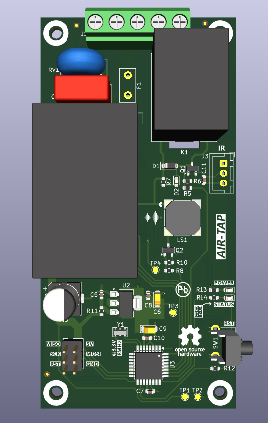
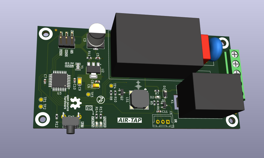
3D views
Top
Bottom (sensor side)
Schematic sections
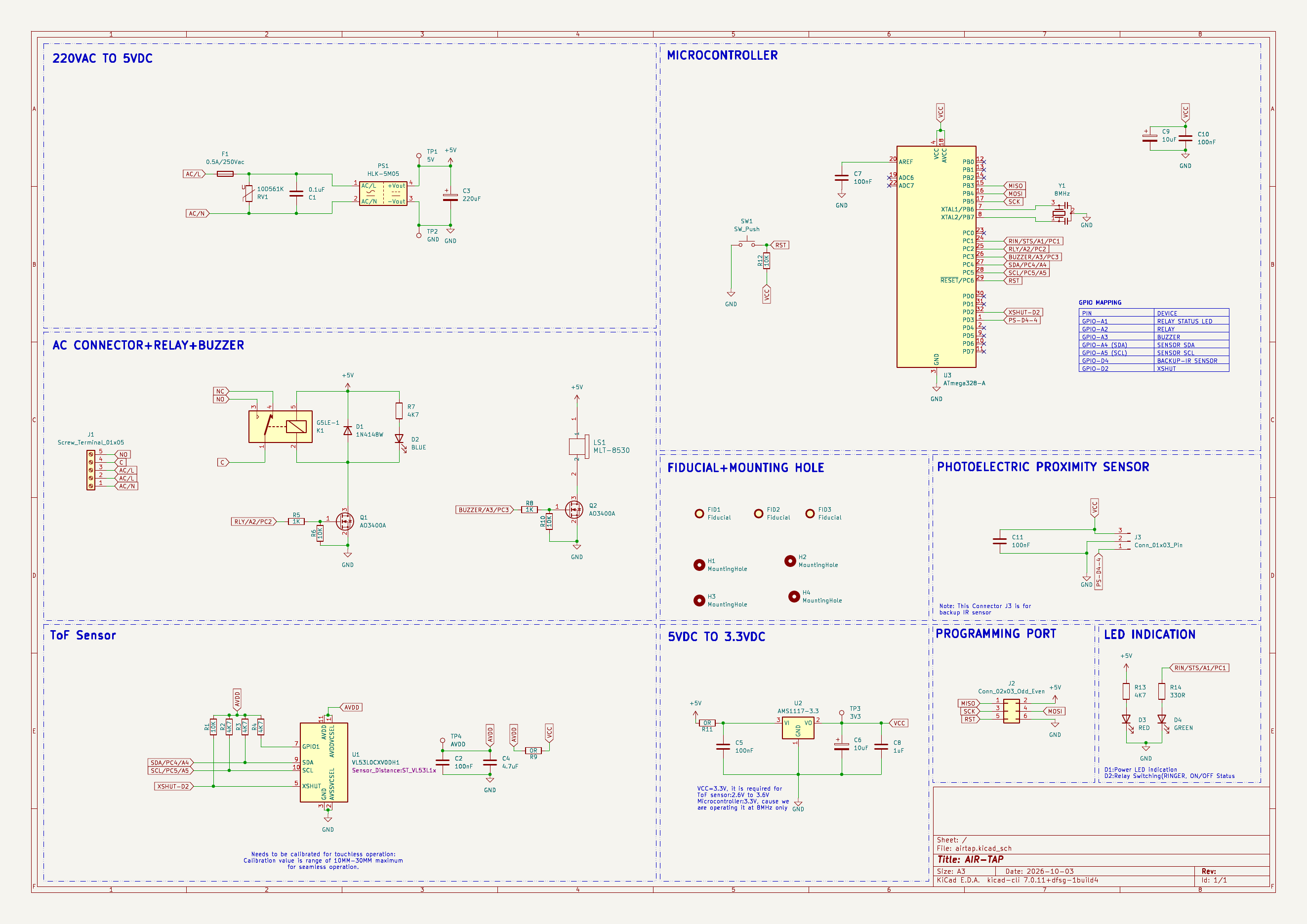
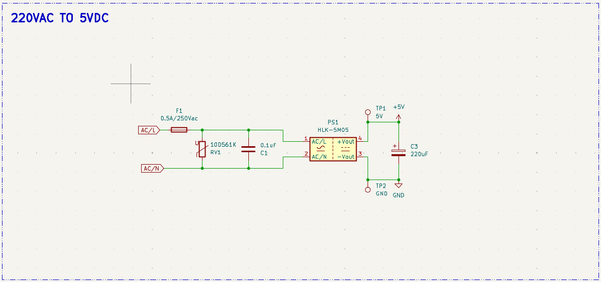
220 VAC → 5 VDC
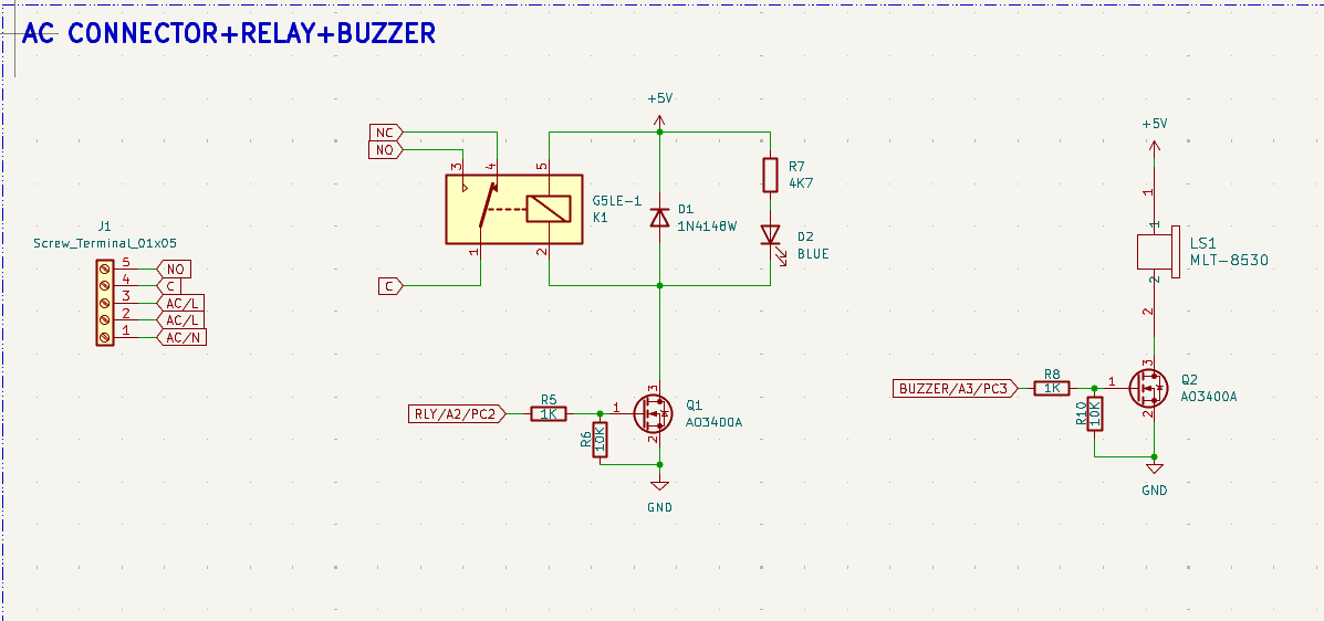
AC connector, relay & buzzer
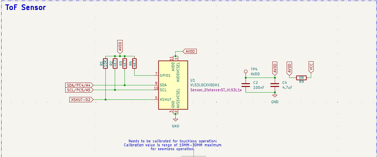
ToF sensor
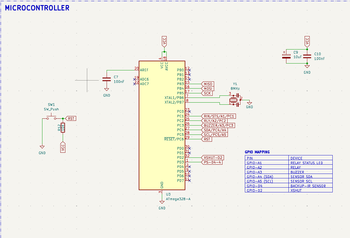
Microcontroller
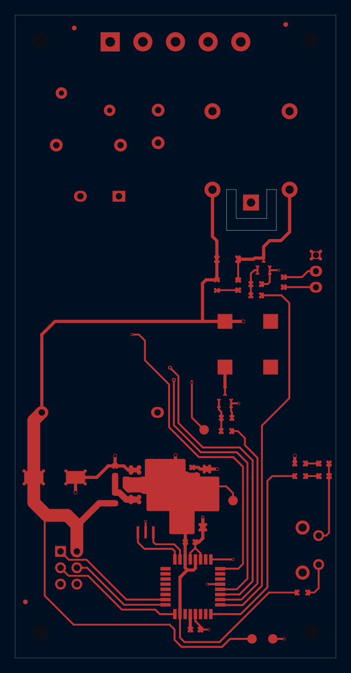
Layer views
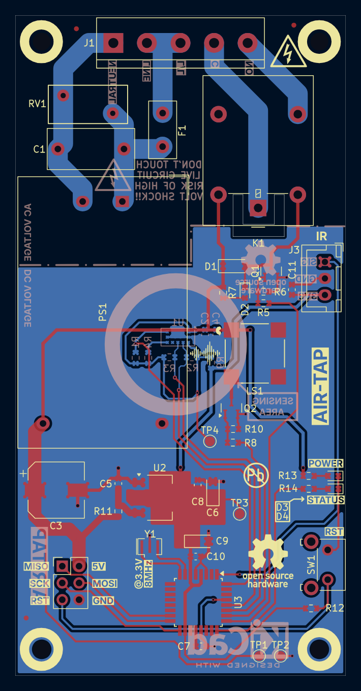
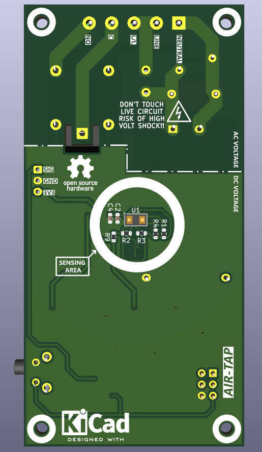
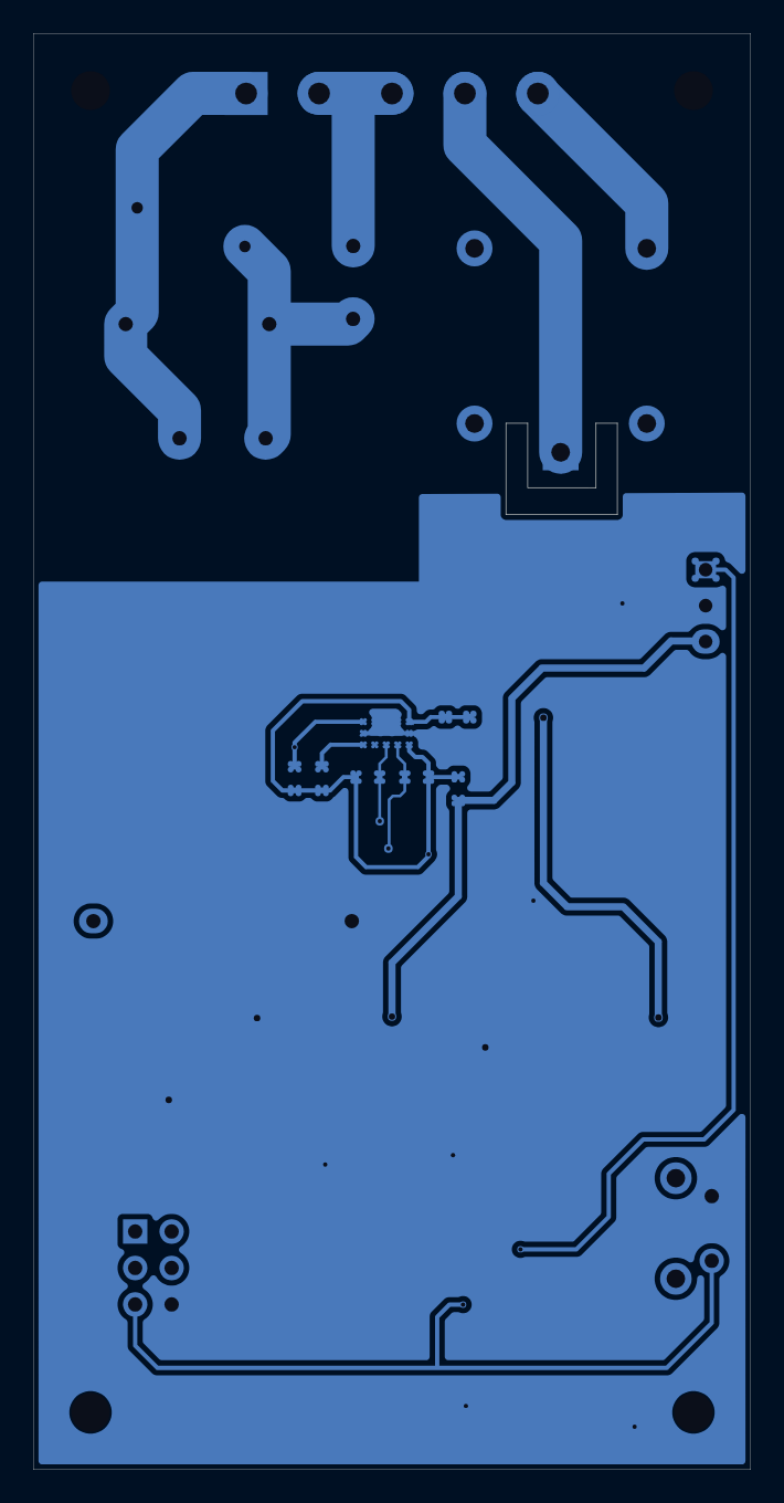
Front copper
Back copper
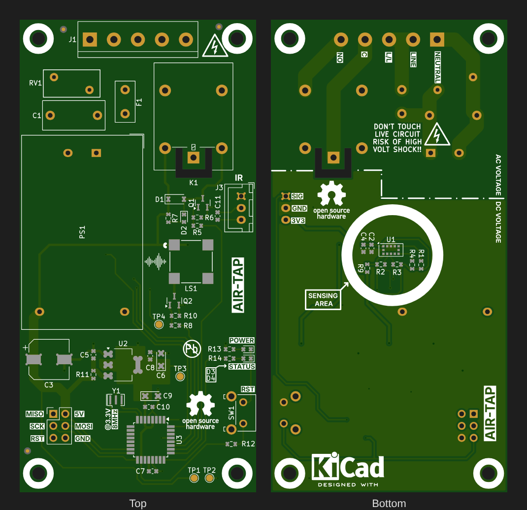
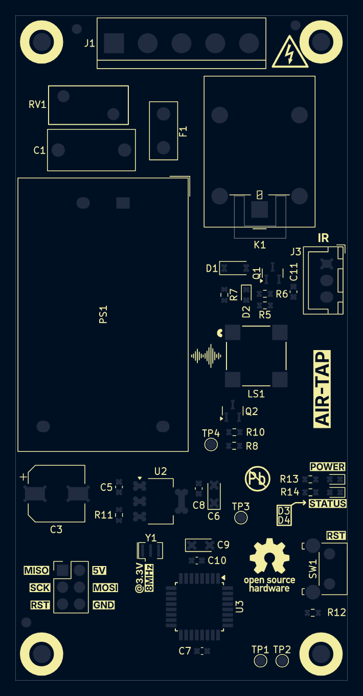
Front silkscreen
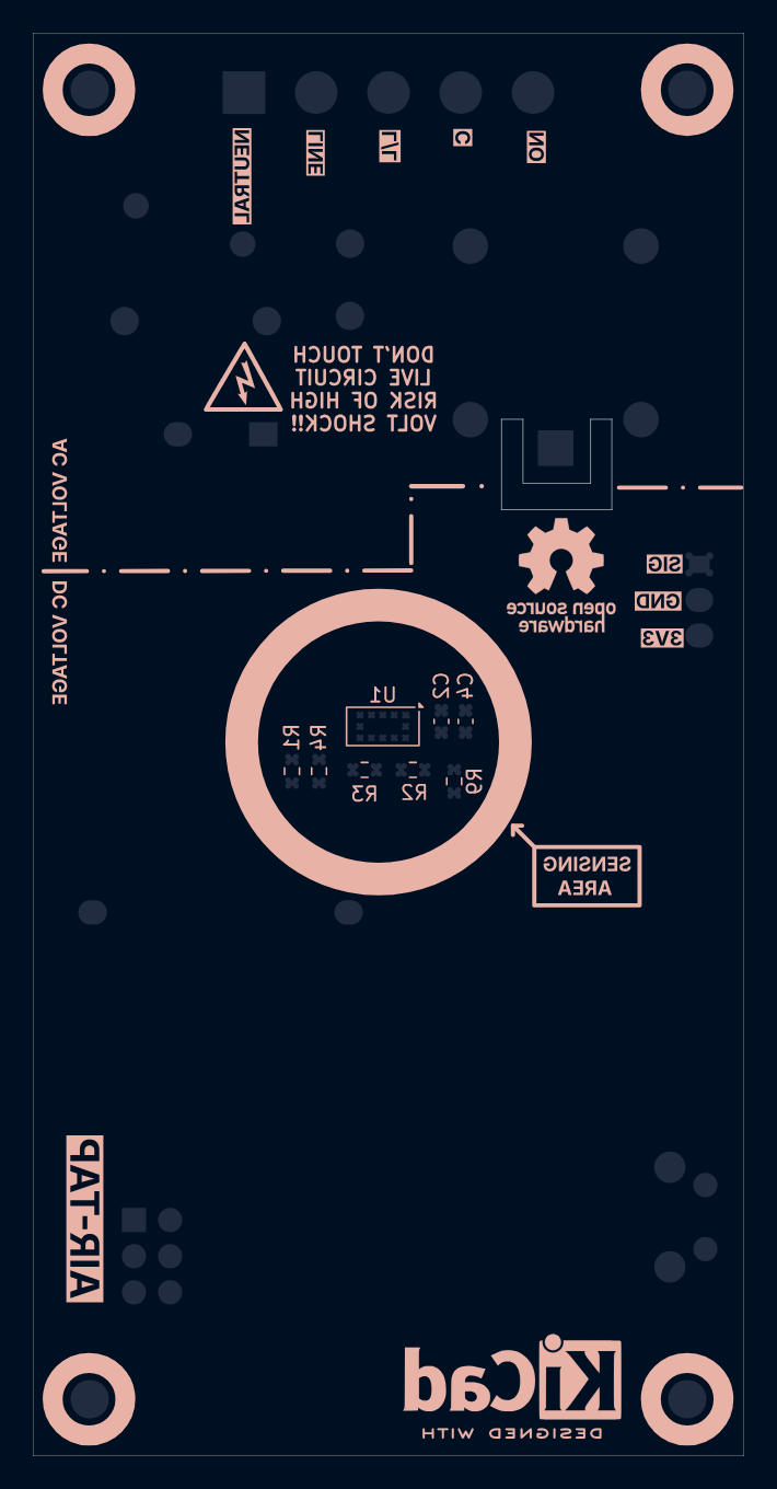
Back silkscreen
Overview
Block
Parts
Function
220 VAC → 5 VDC
F1 fuse, RV1 MOV, C1, PS1 HLK-5M05, C3
Fused, surge-protected isolated AC-DC module
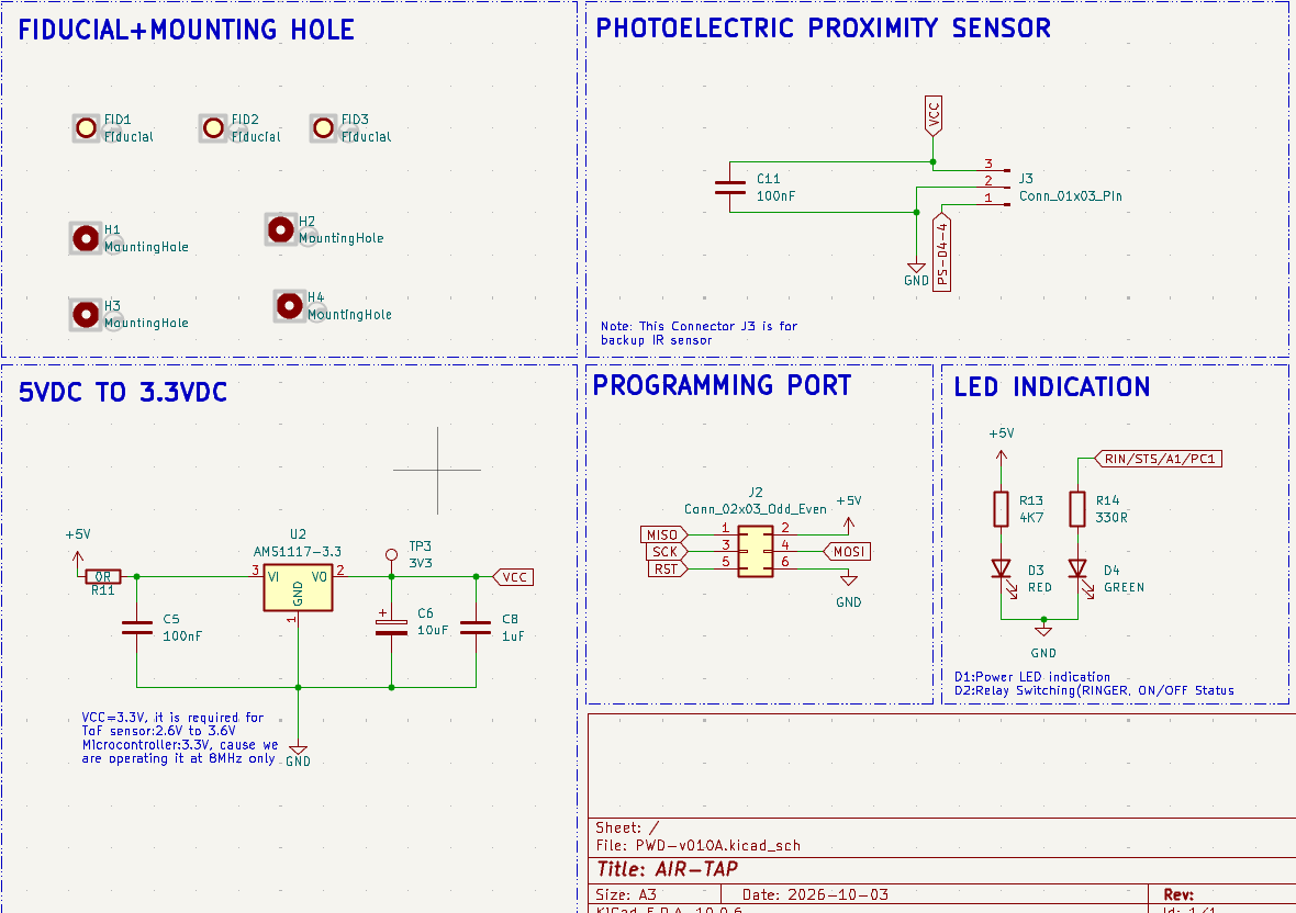
5 V → 3.3 V
U2 AMS1117-3.3 + decoupling
Powers the MCU and sensor
Microcontroller
U3 ATmega328-A, Y1 8 MHz, SW1 reset
Reads the sensor, drives the relay, buzzer and LEDs
D2 blue (relay), D3 red (power), D4 green (status)
Visual status
Programming
J2 2×3 ICSP
Flash with USBasp / AVRISP
Backup sensor
J3 3-pin
Optional IR proximity sensor input
Working Principle
Power: mains enters on J1 (LINE / NEUTRAL) through fuse F1 (0.5 A). MOV RV1 (10D561K) clamps surges, and the HLK-5M05 isolated module produces 5 V. The AMS1117 then makes 3.3 V for the ATmega328 and the VL53L0X.
Sensing: the VL53L0X sends out infrared laser pulses and measures their time of flight. The ATmega328 reads the distance over I²C (SDA = PC4, SCL = PC5).
Decision: when a hand is held inside the calibrated 10–30 mm window, the firmware toggles the load state.
Switching: PC2 drives Q1 (AO3400A logic-level MOSFET), which energises relay K1. D1 clamps the coil's flyback spike. The relay's NO / C / NC contacts are brought out on J1.
Feedback: PC3 drives the buzzer through Q2, the blue LED shows the relay state, and the green LED (PC1) shows status.
GPIO Mapping
ATmega328 Pin
Signal
Function
PC1 / A1
STS
Relay status LED
PC2 / A2
RLY
Relay driver (Q1)
PC3 / A3
BUZZER
Buzzer driver (Q2)
PC4 / A4
SDA
VL53L0X I²C data
PC5 / A5
SCL
VL53L0X I²C clock
PD2 / D2
XSHUT
VL53L0X shutdown / reset
PD4 / D4
IR-BKP
Backup IR sensor (J3)
J1: AC Terminal (5-way)
Pin
Label
Description
1
L/L
AC line (live) in
2
N
AC neutral in
3
NO
Relay normally-open
4
C
Relay common
5
NC
Relay normally-closed
Wire the load between NO and neutral, and connect C to line, so the load is off until triggered.
Key Equations
ToF ranging:
text
d = (c × t) / 2 c = 3×10⁸ m/s, t = round-trip time of the laser pulse
Relay coil drive (G5LE-1, 5 V coil ≈ 72 Ω):
text
I_coil ≈ 5 V / 72 Ω ≈ 70 mA → switched by AO3400A (R_DS(on) ≈ 30 mΩ at V_GS = 2.5 V)
LED current (3.3 V rail):
text
I_LED = (3.3 − V_F) / R e.g. (3.3 − 2.0) / 330 Ω ≈ 4 mA
Specifications
Parameter
Value
Input
220 V AC, 50 Hz
Load Switching
SPDT relay (G5LE-1), NO / C / NC on screw terminal
Setup: in the Arduino IDE, install MiniCore (board manager URL https://raw.githubusercontent.com/MCUdude/MiniCore/master/package_MCUdude_MiniCore_index.json), then choose ATmega328, External 8 MHz, 3.3 V. Install the VL53L0X library by Pololu, and flash through J2 with a USBasp.
Design Notes
J3 footprint: the backup IR connector (J3) has no footprint assigned in the schematic, although the PCB has one. Assign it, for example PinHeader_1x03_P2.54mm, before running "Update PCB from Schematic", or KiCad will flag it.
Isolation: the AC/DC boundary is marked on the silkscreen. For extra safety, consider adding a routed isolation slot between the mains section and the logic section.
C1 must be an X2-rated safety capacitor.
Load rating: the relay is rated 10 A, but the fuse (0.5 A) protects the logic supply only. Fuse the load circuit separately, sized for your appliance.
3D models: the vendor 3D models (relay, buzzer, terminal, switch) aren't included, so KiCad's 3D viewer shows those parts without a body. The 3D renders in this folder were made with them.
Open-source library of power electronics converter topologies — KiCad schematics, working principles, use cases, and design notes for DC-DC, AC-DC, DC-AC, and AC-AC converters. Free to use, modify, and build on.
Open-source library of power electronics converter topologies — KiCad schematics, working principles, use cases, and design notes for DC-DC, AC-DC, DC-AC, and AC-AC converters. Free to use, modify, and build on.
Open-source library of power electronics converter topologies — KiCad schematics, working principles, use cases, and design notes for DC-DC, AC-DC, DC-AC, and AC-AC converters. Free to use, modify, and build on.
Open-source library of power electronics converter topologies — KiCad schematics, working principles, use cases, and design notes for DC-DC, AC-DC, DC-AC, and AC-AC converters. Free to use, modify, and build on.
Open-source library of power electronics converter topologies — KiCad schematics, working principles, use cases, and design notes for DC-DC, AC-DC, DC-AC, and AC-AC converters. Free to use, modify, and build on.
Open-source library of power electronics converter topologies — KiCad schematics, working principles, use cases, and design notes for DC-DC, AC-DC, DC-AC, and AC-AC converters. Free to use, modify, and build on.
Open-source library of power electronics converter topologies — KiCad schematics, working principles, use cases, and design notes for DC-DC, AC-DC, DC-AC, and AC-AC converters. Free to use, modify, and build on.
A simple, low-cost DC fan speed controller built around the classic NE555 timer IC operating in astable mode. Fan speed is adjusted by varying the PWM duty cycle via a potentiometer, while a TIP122 Darlington transistor…
Built an analog DC motor speed controller using an NE555 timer IC and LM3914 LED bar graph for duty-cycle visualization. Designed the circuit schematic in KiCad, gaining experience in PWM and analog motor control
⚡ NE555 PWM DC motor speed controller PCB designed in KiCad, featuring adjustable speed control, TIP122 driver stage, flyback protection, screw terminals, and 3D PCB renders.
PCB design of a DC motor speed controller using the 555 timer IC to generate a PWM signal for speed control. Includes circuit schematic and PCB layout for motor speed regulation by adjusting the PWM duty cycle.
A 555-timer-based DC motor speed controller designed in KiCad — uses a variable-duty-cycle PWM signal driven through a power transistor to control motor speed with a single potentiometer.
21 parts
Questions
How big is the Dc motor speed controller PCB?
It measures 56.5 × 29 mm and has 2 copper layers, 1.6 mm thick.
What parts does the Dc motor speed controller use?
19 parts, built around the NE555P and TIP122. The full list of its parts is on this page, with links to each part's symbol and footprint where PCBKit's library has them.
Where can I download the Dc motor speed controller KiCad files?
From the ajkumar-1907/POWER-ELECTRONICS-LIB repository on GitHub, at the commit this page was made from: the board is dc-motor-speed-controller/dc-motor-speed-controller.kicad_pcb and its schematic air-quality-monitor/air-quality-monitor.kicad_sch. PCBKit opens the board in the browser, with nothing to install.
Can I use the Dc motor speed controller design in my own project?
Its repository publishes it under the MIT licence: you may reuse it on that licence's terms (keep the author's notice, and for a copyleft licence share your changes alike).