Skip to the content
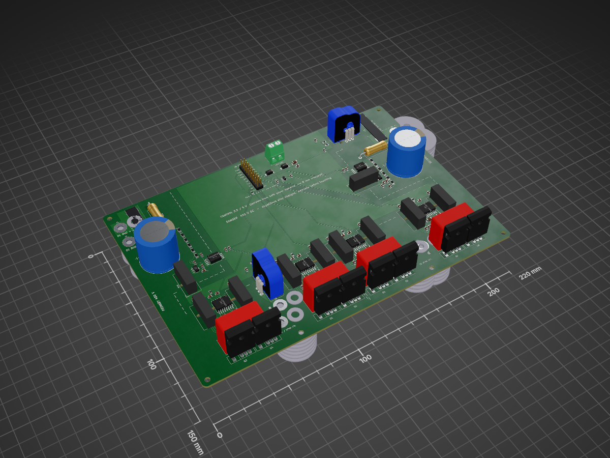
4 layers220 × 150 mmDual active bridge, the printed circuit board in 3D

Open-source library of power electronics converter topologies — KiCad schematics, working principles, use cases, and design notes for DC-DC, AC-DC, DC-AC, and AC-AC converters. Free to use, modify, and build on.

Size
220 × 150 mm
Copper layers
4
Thickness
1.6 mm
Parts
174
Nets
118
Pads
491
Tracks, vias
1,397, 192
Pours
26
Routed
Yes
KiCad
KiCad 10.0 (file 20260206)
Created
18 Sep 2026
Updated
3 Oct 2026

Overview

Dual active bridge is an open-source printed circuit board by ajkumar-1907, from the ajkumar-1907/POWER-ELECTRONICS-LIB repository on GitHub, published under the MIT licence. It is a 4-layer board of 220 × 150 mm with 174 parts on 118 nets, routed with 1,397 tracks and 192 vias.

It is built around the MGJ2D051505SC, UCC21520DW and AMC1311BDWV, with the 78L05, AP2112K-3.3 and BAT54J among its other parts. Its parts include 70 capacitors, 47 resistors, 10 diodes, 10 connectors and 9 ICs. It belongs with the interfaces and adapters boards of this library.

Main components

8

README

airtap/README.md

AirTap: Touchless AC Switch

A touchless, proximity-triggered relay controller for 220 V AC loads. Hold your hand 10–30 mm above the sensing area and a VL53L0X time-of-flight sensor detects it. The ATmega328 then toggles an onboard relay to switch a lamp, fan or other mains appliance, with no physical contact.

Credit: AirTap is a fork of ProxiWave-D (PWD-v010A) by Ampnics, released under the MIT License. The circuit, PCB layout and test firmware are Ampnics' original design. This fork re-brands the board silkscreen as "AIR-TAP", ports the project to KiCad 10, and adds Gerbers, renders and documentation. See NOTICE.md.

⚠️ DANGER: mains voltage. The AC side of this board carries 220 V. Never touch it while it's powered, keep it in an enclosure, and only build it if you're experienced with mains wiring.

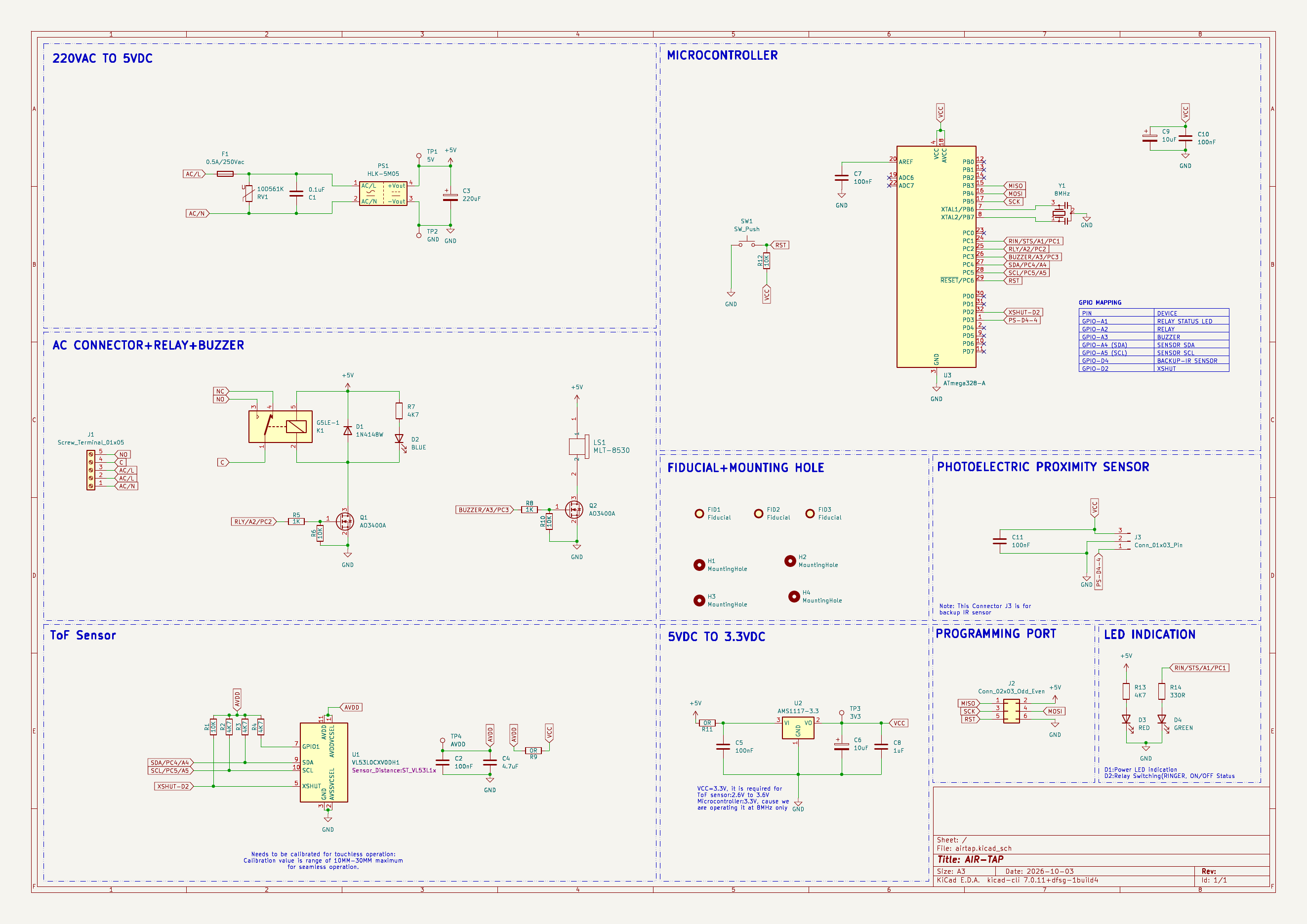
Schematic

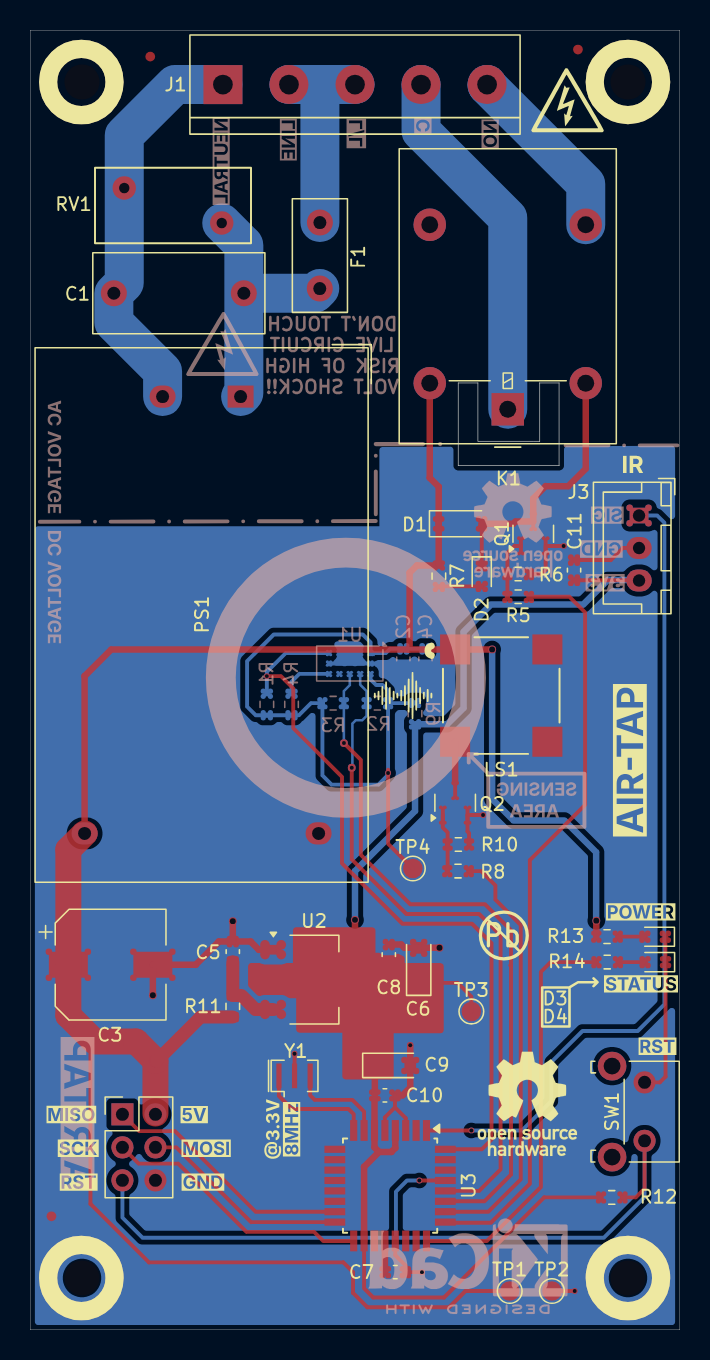
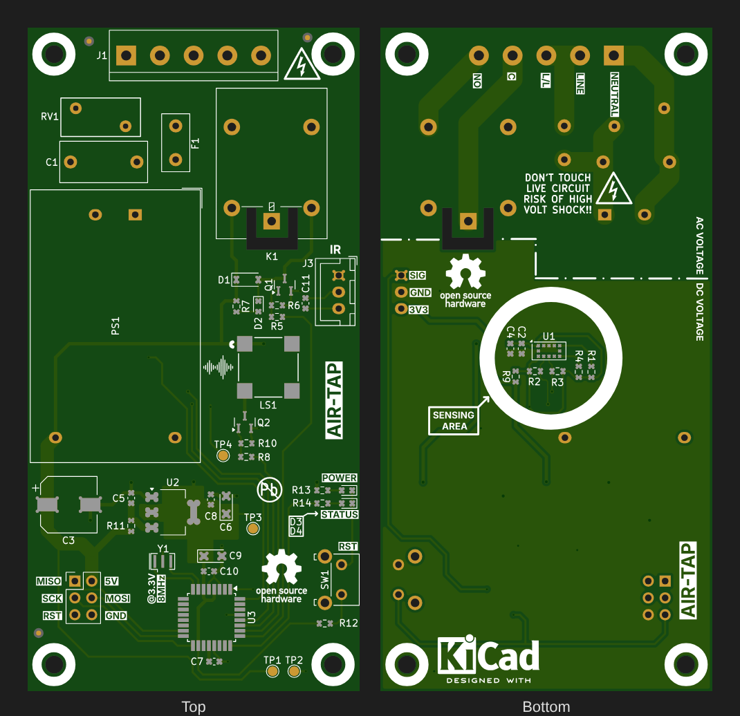
PCB Layout

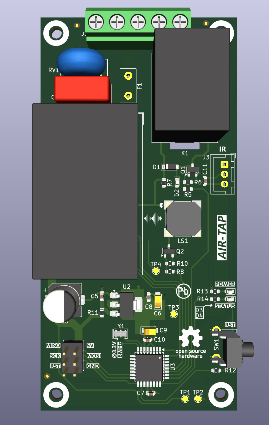
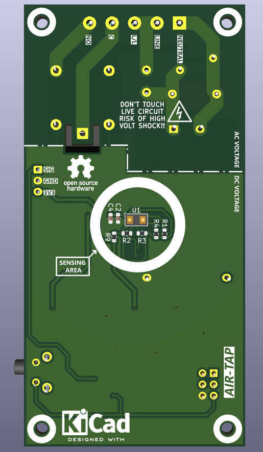
PCB Top and Bottom

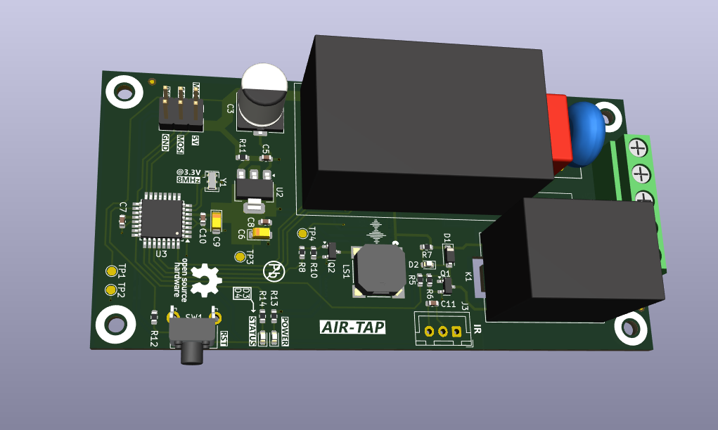
3D views

TopBottom (sensor side)
3D top3D bottom

3D angled view

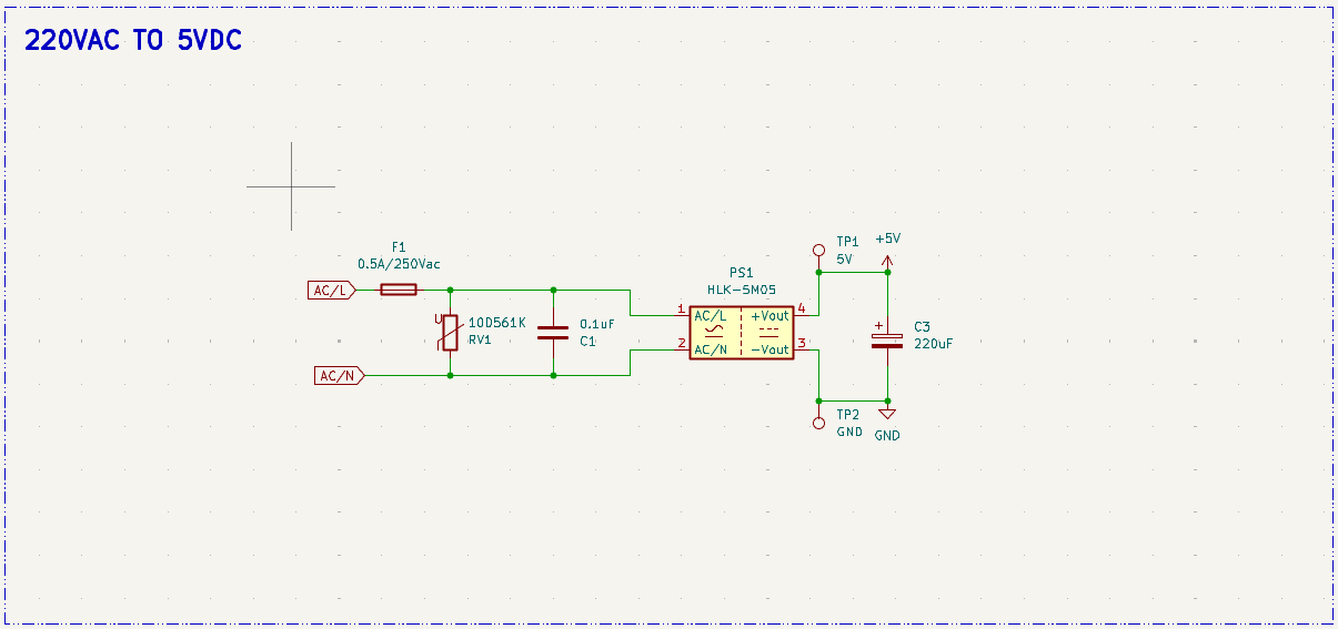
Schematic sections

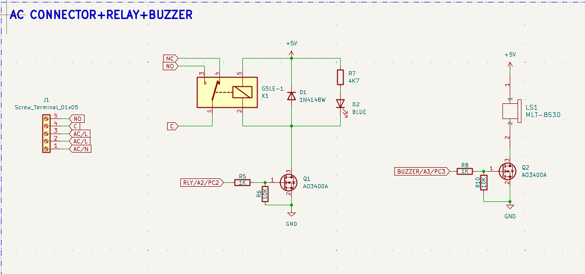
220 VAC → 5 VDCAC connector, relay & buzzer
Power supplyRelay and buzzer
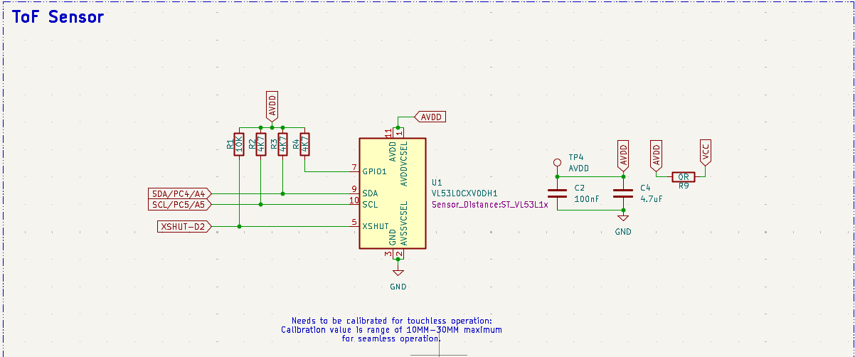
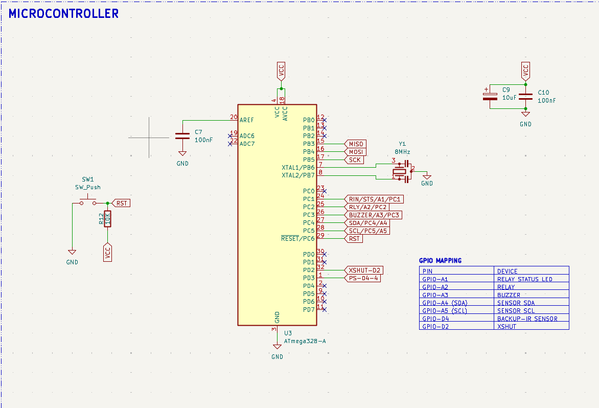
ToF sensorMicrocontroller

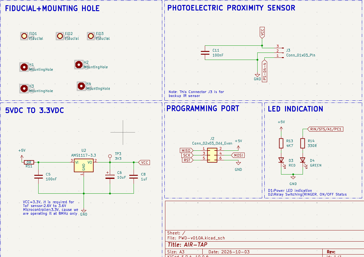
3.3 V regulator, programming port, LEDs, IR connector

Layer views

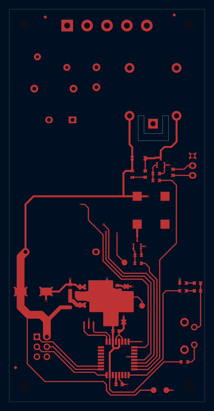
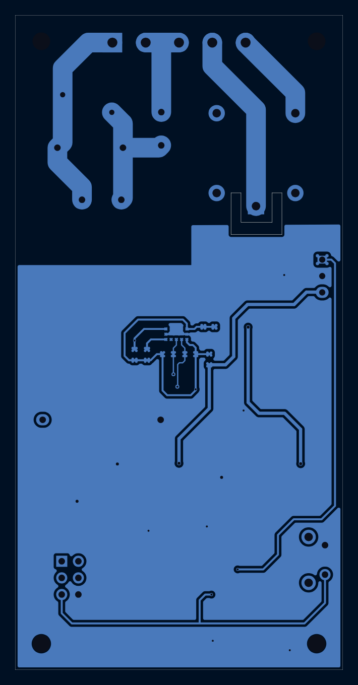
Front copperBack copper
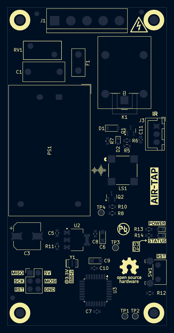
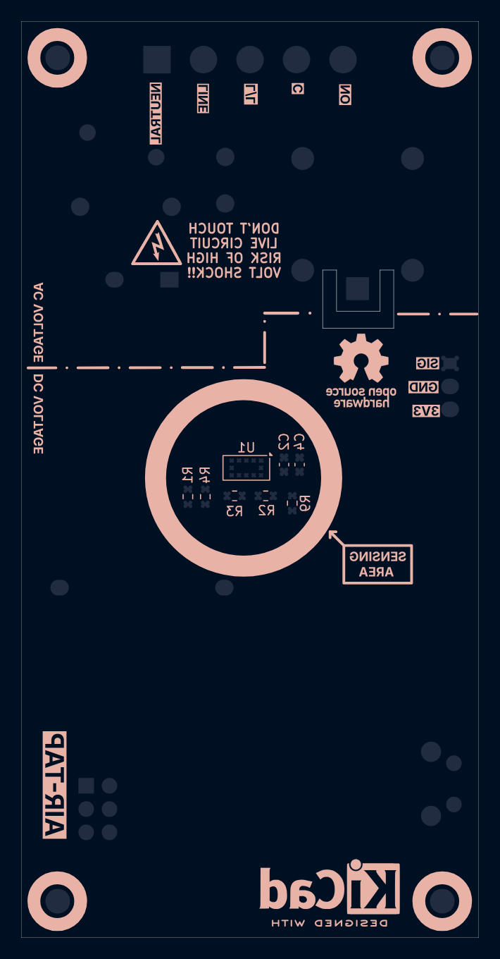
Front silkscreenBack silkscreen

Overview

BlockPartsFunction
220 VAC → 5 VDCF1 fuse, RV1 MOV, C1, PS1 HLK-5M05, C3Fused, surge-protected isolated AC-DC module
5 V → 3.3 VU2 AMS1117-3.3 + decouplingPowers the MCU and sensor
MicrocontrollerU3 ATmega328-A, Y1 8 MHz, SW1 resetReads the sensor, drives the relay, buzzer and LEDs
ToF sensorU1 VL53L0X, I²C pull-upsMeasures hand distance (10–30 mm trigger window)
Relay and buzzerK1 G5LE-1, Q1/Q2 AO3400A, D1 flyback, LS1 MLT-8530Switches the AC load; audible feedback
IndicatorsD2 blue (relay), D3 red (power), D4 green (status)Visual status
ProgrammingJ2 2×3 ICSPFlash with USBasp / AVRISP
Backup sensorJ3 3-pinOptional IR proximity sensor input

Working Principle

  1. Power: mains enters on J1 (LINE / NEUTRAL) through fuse F1 (0.5 A). MOV RV1 (10D561K) clamps surges, and the HLK-5M05 isolated module produces 5 V. The AMS1117 then makes 3.3 V for the ATmega328 and the VL53L0X.
  2. Sensing: the VL53L0X sends out infrared laser pulses and measures their time of flight. The ATmega328 reads the distance over I²C (SDA = PC4, SCL = PC5).
  3. Decision: when a hand is held inside the calibrated 10–30 mm window, the firmware toggles the load state.
  4. Switching: PC2 drives Q1 (AO3400A logic-level MOSFET), which energises relay K1. D1 clamps the coil's flyback spike. The relay's NO / C / NC contacts are brought out on J1.
  5. Feedback: PC3 drives the buzzer through Q2, the blue LED shows the relay state, and the green LED (PC1) shows status.

GPIO Mapping

ATmega328 PinSignalFunction
PC1 / A1STSRelay status LED
PC2 / A2RLYRelay driver (Q1)
PC3 / A3BUZZERBuzzer driver (Q2)
PC4 / A4SDAVL53L0X I²C data
PC5 / A5SCLVL53L0X I²C clock
PD2 / D2XSHUTVL53L0X shutdown / reset
PD4 / D4IR-BKPBackup IR sensor (J3)

J1: AC Terminal (5-way)

PinLabelDescription
1L/LAC line (live) in
2NAC neutral in
3NORelay normally-open
4CRelay common
5NCRelay normally-closed

Wire the load between NO and neutral, and connect C to line, so the load is off until triggered.

Key Equations

ToF ranging:

text
d = (c × t) / 2        c = 3×10⁸ m/s, t = round-trip time of the laser pulse

Relay coil drive (G5LE-1, 5 V coil ≈ 72 Ω):

text
I_coil ≈ 5 V / 72 Ω ≈ 70 mA      → switched by AO3400A (R_DS(on) ≈ 30 mΩ at V_GS = 2.5 V)

LED current (3.3 V rail):

text
I_LED = (3.3 − V_F) / R      e.g. (3.3 − 2.0) / 330 Ω ≈ 4 mA

Specifications

ParameterValue
Input220 V AC, 50 Hz
Load SwitchingSPDT relay (G5LE-1), NO / C / NC on screw terminal
Logic Supply5 V (HLK-5M05) → 3.3 V (AMS1117)
MCUATmega328-A @ 8 MHz, 3.3 V
SensorVL53L0X ToF, 10–30 mm calibrated trigger
Protection0.5 A fuse, 10D561K MOV, flyback diode
ProgrammingICSP 2×3
Board Size50 × 100 mm, 2-layer, 4 × M2.5 mounting holes, fiducials

Bill of Materials (key parts)

RefValuePackage
PS1HLK-5M05 (220 VAC → 5 V)Module
U3ATmega328-ATQFP-32
U1VL53L0CXV0DH1 (VL53L0X)LGA
U2AMS1117-3.3SOT-223
K1Omron G5LE-1 relay, 5 V coilTHT
Q1, Q2AO3400A N-MOSFETSOT-23
D11N4148WSOD-123
F10.5 A / 250 VAC fuseLittelfuse 395
RV110D561K MOVDisc 12 mm
C10.1 µF X2 film13 × 6 mm
C3220 µF electrolytic8 × 10 mm
LS1MLT-8530 buzzerSMD
Y18 MHz resonatorSMD 3-pin
J15-way screw terminal, 5.08 mmTHT

Plus 0603 resistors, capacitors and LEDs; see the schematic for full values.

Firmware

Test sketches by the original author are in firmware/test-codes/:

SketchTests
ToF-SensorVL53L0X I²C ranging (prints distance over UART)
RelayRelay coil driver and flyback diode
Relay-LedRelay status LED
BuzzerBuzzer driver

Setup: in the Arduino IDE, install MiniCore (board manager URL https://raw.githubusercontent.com/MCUdude/MiniCore/master/package_MCUdude_MiniCore_index.json), then choose ATmega328, External 8 MHz, 3.3 V. Install the VL53L0X library by Pololu, and flash through J2 with a USBasp.

Design Notes

  • J3 footprint: the backup IR connector (J3) has no footprint assigned in the schematic, although the PCB has one. Assign it, for example PinHeader_1x03_P2.54mm, before running "Update PCB from Schematic", or KiCad will flag it.
  • Isolation: the AC/DC boundary is marked on the silkscreen. For extra safety, consider adding a routed isolation slot between the mains section and the logic section.
  • C1 must be an X2-rated safety capacitor.
  • Load rating: the relay is rated 10 A, but the fuse (0.5 A) protects the logic supply only. Fuse the load circuit separately, sized for your appliance.
  • 3D models: the vendor 3D models (relay, buzzer, terminal, switch) aren't included, so KiCad's 3D viewer shows those parts without a body. The 3D renders in this folder were made with them.

Files in This Folder

FileDescription
airtap.kicad_pro / .kicad_sch / .kicad_pcbKiCad 10 project, schematic and PCB
airtap-PTH.drl / airtap-NPTH.drlDrill files
gerbers/Gerber set for fabrication (incl. paste layers)
firmware/test-codes/Arduino test sketches (original author)
schematic.pngFull schematic image
schematic-*.pngSchematic section close-ups
pcb-3d-top.png / pcb-3d-bottom.png / pcb-3d-angle.png3D renders
pcb-layout2.png / pcb-layout.pngLayout previews
pcb-front-copper.png / pcb-back-copper.pngCopper layer views
pcb-front-silkscreen.png / pcb-back-silkscreen.pngSilkscreen layer views
NOTICE.mdOriginal copyright and license notice

How to Use

  1. Open airtap.kicad_pro in KiCad 10 or later.
  2. To manufacture, zip gerbers/ together with the two .drl files and upload them to any PCB fab.
  3. After assembly, flash the test sketches through J2 to check each block, then load your main firmware.
  4. Calibrate the trigger distance (10–30 mm) for your enclosure.

License

The original ProxiWave-D design is © Ampnics, released under the MIT License (see NOTICE.md). Changes in this fork are released under the repository's MIT License.

Parts

174
QtyValueFootprintReferences
201uFCapacitor_SMD:C_0805_2012MetricC35, C36, C37, C38, C39, C40, C41, C42, C47, C48, C49, C50, C51, C52, C56, C57 +4
162.2uFCapacitor_SMD:C_0805_2012MetricC11, C12, C13, C14, C15, C16, C17, C18, C19, C20, C21, C22, C23, C24, C25, C26
11100nFCapacitor_SMD:C_0805_2012MetricC43, C44, C45, C46, C53, C55, C59, C61, C63, C64, C68
1110kResistor_SMD:R_0805_2012MetricR17, R18, R19, R20, R21, R22, R23, R24, R29, R43, R45
10402k 1%Resistor_SMD:R_1206_3216MetricR30, R31, R32, R33, R34, R36, R37, R38, R39, R40
10MGJ2D051505SCConverter_DCDC:Converter_DCDC_Murata_MGJ2DxxxxxxSC_THTPS1, PS2, PS3, PS4, PS5, PS6, PS7, PS8, PS9, PS10
8100nFCapacitor_SMD:C_1206_3216MetricC27, C28, C29, C30, C31, C32, C33, C34
810RResistor_SMD:R_0805_2012MetricR1, R2, R3, R4, R5, R6, R7, R8
84.7RResistor_SMD:R_0805_2012MetricR9, R10, R11, R12, R13, R14, R15, R16
8BAT54JDiode_SMD:D_SOD-323FD1, D2, D3, D4, D5, D6, D7, D8
8C3M0060065KPackage_TO_SOT_THT:TO-247-4_VerticalQ1, Q2, Q3, Q4, Q5, Q6, Q7, Q8
6M3MountingHole:MountingHole_3.2mm_M3H1, H2, H3, H4, H5, H6
4100nF 1kVCapacitor_SMD:C_1812_4532MetricC7, C8, C9, C10
41uF 630V filmCapacitor_THT:C_Rect_L26.5mm_W11.5mm_P22.50mm_MKS4C3, C4, C5, C6
449.9kResistor_SMD:R_0805_2012MetricR25, R26, R27, R28
4UCC21520DWPackage_SO:SOIC-16W_7.5x10.3mm_P1.27mmU1, U2, U3, U4
210nFCapacitor_SMD:C_0805_2012MetricC65, C66
21nF C0GCapacitor_SMD:C_0805_2012MetricC54, C60
220A 500VDCDAB_3k3W:Fuseholder_Clip-6.3x32mm_PCBF1, F2
2220k 2WResistor_THT:R_Axial_DIN0617_L17.0mm_D6.0mm_P25.40mm_HorizontalR46, R47
24.75kResistor_SMD:R_0805_2012MetricR42, R44
278L05Package_TO_SOT_SMD:SOT-89-3U7, U8
28.06k 0.1%Resistor_SMD:R_1206_3216MetricR35, R41
2AMC1311BDWVPackage_SO:SOIC-8_7.5x5.85mm_P1.27mmU5, U6
2LTSR 25-NPSensor_Current:LEM_LTSR-NPCS1, CS2
2SS34Diode_SMD:D_SMAD9, D10
1100uF 450VCapacitor_THT:CP_Radial_D25.0mm_P10.00mm_SnapInC1
1150uF 450VCapacitor_THT:CP_Radial_D25.0mm_P10.00mm_SnapInC2
122uFCapacitor_SMD:C_1206_3216MetricC67
15V AUX INTerminalBlock_Phoenix:TerminalBlock_Phoenix_MKDS-1,5-2-5.08_1x02_P5.08mm_HorizontalJ10
1AP2112K-3.3Package_TO_SOT_SMD:SOT-23-5U9
1BAT +MountingHole:MountingHole_4.3mm_M4_PadJ3
1BAT -MountingHole:MountingHole_4.3mm_M4_PadJ4
1CONTROLConnector_PinHeader_2.54mm:PinHeader_2x10_P2.54mm_VerticalJ9
1DC BUS +MountingHole:MountingHole_4.3mm_M4_PadJ1
1DC BUS -MountingHole:MountingHole_4.3mm_M4_PadJ2
1XFMR aMountingHole:MountingHole_4.3mm_M4_PadJ5
1XFMR bMountingHole:MountingHole_4.3mm_M4_PadJ6
1XFMR cMountingHole:MountingHole_4.3mm_M4_PadJ7
1XFMR dMountingHole:MountingHole_4.3mm_M4_PadJ8

More from ajkumar-1907/POWER-ELECTRONICS-LIB

7
  • 2 layers50 × 100 mmAirtap, the printed circuit board in 3D

    Airtap

    ajkumar-1907/POWER-ELECTRONICS-LIB

    Open-source library of power electronics converter topologies — KiCad schematics, working principles, use cases, and design notes for DC-DC, AC-DC, DC-AC, and AC-AC converters. Free to use, modify, and build on.

    62 parts1MIT
  • 2 layers68 × 47.4 mmAir quality monitor, the printed circuit board in 3D

    Air quality monitor

    ajkumar-1907/POWER-ELECTRONICS-LIB

    Open-source library of power electronics converter topologies — KiCad schematics, working principles, use cases, and design notes for DC-DC, AC-DC, DC-AC, and AC-AC converters. Free to use, modify, and build on.

    59 parts1MIT
  • 2 layers56.5 × 29 mmDc motor speed controller, the printed circuit board in 3D

    Dc motor speed controller

    ajkumar-1907/POWER-ELECTRONICS-LIB

    Open-source library of power electronics converter topologies — KiCad schematics, working principles, use cases, and design notes for DC-DC, AC-DC, DC-AC, and AC-AC converters. Free to use, modify, and build on.

    19 parts1MIT
  • 2 layers48.8 × 37.5 mmTransformerless power supply, the printed circuit board in 3D

    Transformerless power supply

    ajkumar-1907/POWER-ELECTRONICS-LIB

    Open-source library of power electronics converter topologies — KiCad schematics, working principles, use cases, and design notes for DC-DC, AC-DC, DC-AC, and AC-AC converters. Free to use, modify, and build on.

    19 parts1MIT
  • 2 layers31 × 15 mmUsb to uart converter, the printed circuit board in 3D

    Usb to uart converter

    ajkumar-1907/POWER-ELECTRONICS-LIB

    Open-source library of power electronics converter topologies — KiCad schematics, working principles, use cases, and design notes for DC-DC, AC-DC, DC-AC, and AC-AC converters. Free to use, modify, and build on.

    19 parts1MIT
  • 2 layers53 × 36 mmBuck converter, the printed circuit board in 3D

    Buck converter

    ajkumar-1907/POWER-ELECTRONICS-LIB

    Open-source library of power electronics converter topologies — KiCad schematics, working principles, use cases, and design notes for DC-DC, AC-DC, DC-AC, and AC-AC converters. Free to use, modify, and build on.

    11 parts1MIT
  • 2 layers30.5 × 27.8 mmServo tester, the printed circuit board in 3D

    Servo tester

    ajkumar-1907/POWER-ELECTRONICS-LIB

    Open-source library of power electronics converter topologies — KiCad schematics, working principles, use cases, and design notes for DC-DC, AC-DC, DC-AC, and AC-AC converters. Free to use, modify, and build on.

    10 parts1MIT

Similar boards

  • 4 layers231 × 67 mmBESC G2, the printed circuit board in 3D

    BESC G2

    galpavlin/BESC-G2

    BESC second generation

    300 parts58
  • 2 layers94.5 × 228 mmRampedFetCoil, the printed circuit board in 3D

    RampedFetCoil

    flyingperson23/RampedFetCoil

    157 parts2
  • 2 layers100 × 100 mmSchematic MD, the printed circuit board in 3D

    Schematic MD

    Mochizuki12/schematic_MD

    180 partsCC-BY-SA-4.0
  • 2 layers96.5 × 52.5 mmGate Driver, the printed circuit board in 3D

    Gate Driver

    omarafif-ee/400V-SiC-Half-Bridge-Driver

    400 V DC isolated half-bridge gate driver PCB using Wolfspeed SiC MOSFETs and TI UCC21520 in KiCad, with LTspice transient verification

    27 parts
  • 2 layers100 × 100 mmSchematic MD, the printed circuit board in 3D

    Schematic MD

    SurugaElectric/md_pcb

    SurugaElec. 2ch MD © 2025 by SurugaElectric is licensed under CC BY-SA 4.0

    195 partsCC-BY-SA-4.0
  • 6 layers70.4 × 125.2 mmPower Board, the printed circuit board in 3D

    Power Board

    vinhphannn/ESC-G474-24S

    Dự án phát triển mạch điều khiển tốc độ điện tử (ESC - Electronic Speed Controller) điện áp cao (100V) sử dụng vi điều khiển STM32G474, hướng đến các ứng dụng công suất lớn như Drone công nghiệp, máy bay không người lái…

    248 parts
  • 4 layers200 × 180 mmDevice, the printed circuit board in 3D

    Device

    jayis1/hacker-devices

    Full-cycle hardware designs for security research devices — each device is a subfolder with its own README, schematics, PCB layout, and software stack

    16 parts2

Questions

How big is the Dual active bridge PCB?

It measures 220 × 150 mm and has 4 copper layers, 1.6 mm thick.

What parts does the Dual active bridge use?

174 parts, built around the MGJ2D051505SC, UCC21520DW, AMC1311BDWV and 78L05. The full list of its parts is on this page, with links to each part's symbol and footprint where PCBKit's library has them.

Where can I download the Dual active bridge KiCad files?

From the ajkumar-1907/POWER-ELECTRONICS-LIB repository on GitHub, at the commit this page was made from: the board is dual-active-bridge/dual-active-bridge.kicad_pcb and its schematic air-quality-monitor/air-quality-monitor.kicad_sch. PCBKit opens the board in the browser, with nothing to install.

Can I use the Dual active bridge design in my own project?

Its repository publishes it under the MIT licence: you may reuse it on that licence's terms (keep the author's notice, and for a copyleft licence share your changes alike).