
2 layers65 × 56 mm

 afcreamer/Open-ED5
CAME Entrotec ED5 Zigbee Door Opener
Door opener mini is an open-source printed circuit board by afcreamer, from the afcreamer/Open-ED5 repository on GitHub, published under the CC0-1.0 licence. It is a 2-layer board of 59.5 × 56 mm with 23 parts on 16 nets, routed with 80 tracks and 0 vias.
Its parts include 7 resistors, 4 connectors, 3 ICs and 1 transistor. It belongs with the home automation and IoT and radio and wireless boards and the ESP32 and RISC-V boards of this library.




Open your building's front door from your phone. Zigbee, local, no cloud, no subscription.
A hand-solderable PCB shaped to fit inside the CAME Entrotec ED5 handset itself, in the empty space above its PCB. It wires to the handset's existing terminals and exposes the entryphone to Home Assistant through Zigbee2MQTT. Someone buzzes your flat, your phone gets an actionable notification, you tap Open door, and the communal door opens.
Designed for and tested on an ED5 handset backed by an APEX controller, so the board outline, connector placement and height are all dimensioned around that handset's internal cavity. Other Entrotec systems, meaning Elite, legacy DC, and the ED3+ / ED4+ handsets the ED5 replaces, share the same terminals and would likely work electrically, but the board will not necessarily fit their cases; see Compatibility.
Schematic · Wiring diagram · Beginner's build guide · BOM · Firmware
There is no separate box on the wall and nothing on show. The handset looks and works exactly as before, nothing is cut or drilled, and the board runs from the entryphone's own supply, so no extra PSU, no mains wiring, and no second thing to explain to anyone else in the building.
Why the off-the-shelf kit struggles here: CAME Entrotec systems only release the door during an active call with the handset off-hook. As far as I can tell that interlock defeats every off-the-shelf smart intercom adapter I could find, such as Nuki Opener and Ring Intercom, because I don't believe any of them can emulate a lifted handset. This board does, using resistive loads on the speaker and microphone pairs.
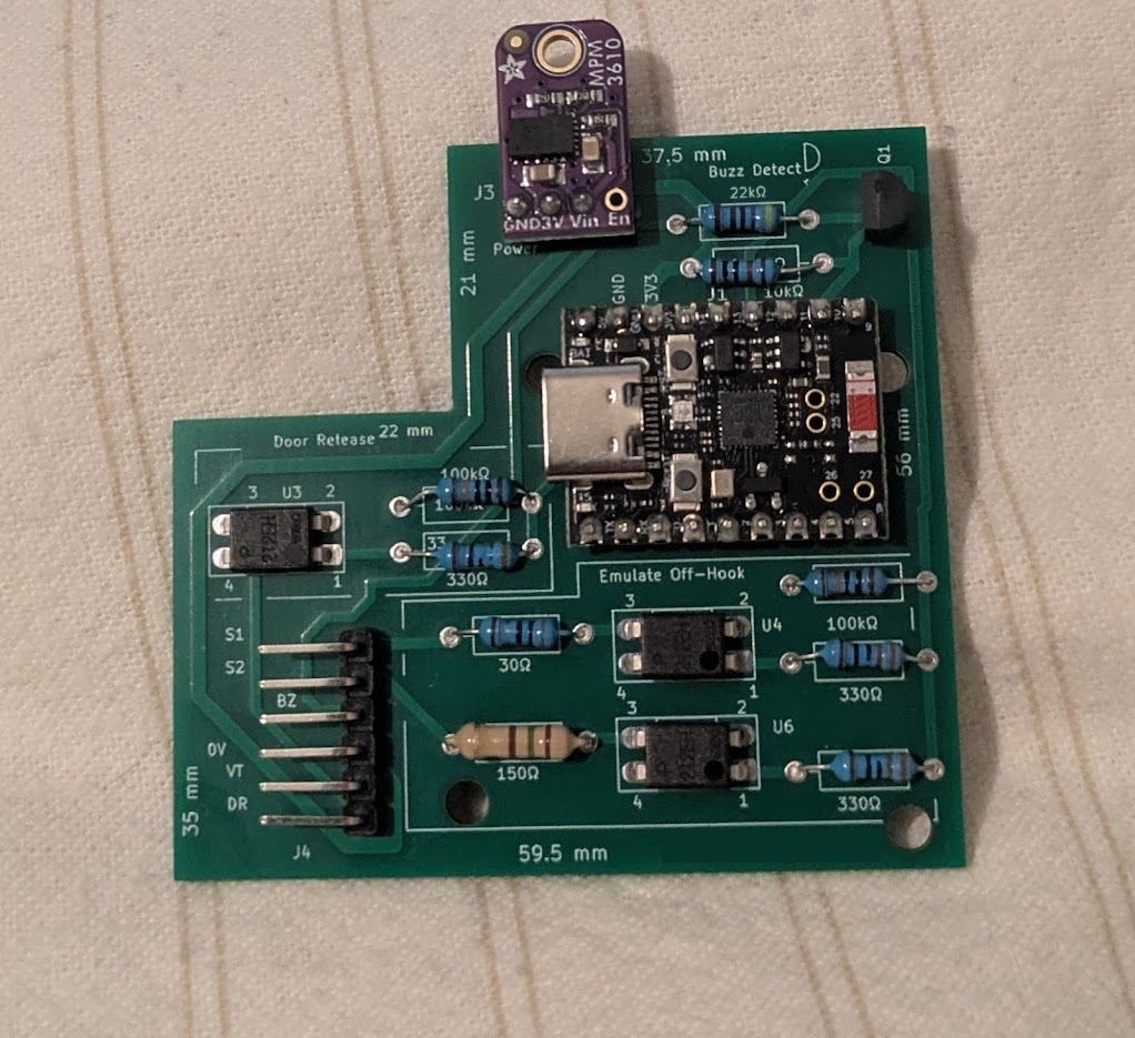
An assembled board. Everything is through-hole; the ESP32-H2 SuperMini and the MPM3610 buck module solder onto 2.54 mm pin headers.
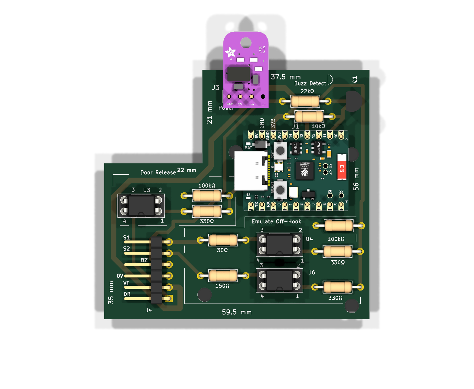
Two things:
It is not meant for opening the door to visitors remotely or automatically. The board carries no audio. It emulates the electrical load of a lifted handset, not a conversation, so there is no way to hear who is at the panel and no way to verify them. Opening the door to whoever happens to be standing there is not something this should be used for.
The sensible middle ground is a fallback for people you are expecting: a relative arrives, rings your mobile to say they are outside, and you let them in. You have verified them by another route. Because it runs through Home Assistant, that works from anywhere.
CAME Entrotec systems have a deliberate interlock: the door release only works during an active call, with the handset off-hook. Pulling the DR line to 0 V on its own does nothing.
That design decision is why the off-the-shelf products struggle. They all connect the same way, with a doorbell-detect input and a door-release contact, and none of the ones I could find have anywhere to plug the audio pair in.
Real reports from people who hit this wall:
That Nuki thread contains an open question, unanswered since 2021:
"Whether connecting S1/S2 (microphone/speaker) cables would simulate an active call state and enable functionality."
It does. That's what this board is.
Three independent channels, all on the handset's existing terminal block. Nothing is intercepted, because the board sits in parallel and the handset carries on working normally.
When the handset is on its cradle, the hook switch disconnects the speaker and microphone,
so S1 and S2 present no load. The system reads that as "on-hook".
The board puts its own loads across those lines through solid-state relays:
S1 ──[ RS1 30R ]── AQY212 (U4) ── 0V     emulates the speaker
S2 ──[ RS2 150R ]── AQY212 (U6) ── 0V    emulates the microphone
Close both and the system believes someone lifted the receiver. No audio hardware is involved, because the entryphone only checks that something with roughly the right impedance is hanging on those lines. Both PhotoMOS are driven from one GPIO so they always switch together.
This is transient: the board is on-hook at idle, goes off-hook for about five seconds to open the door, then releases.
DR is pulled to 0V through a third AQY212, for a firmware-timed 1.5 s pulse. The pulse
self-terminates in firmware, so the strike releases even if the network drops mid-command.
The call tone on BZ is a 0.88 V pulsed signal, far below an optocoupler LED's ~1.2 V
turn-on, so the usual opto-isolated approach cannot see it. Instead a single 2N3904 senses it
directly:
BZ ──[ R11 22k ]── base
                   collector ── IO10 (10k pull-up to 3V3)
emitter ── 0VEverything below was measured on a live installation. If you're adapting this, these are the numbers to check against your own system first.
| Property | Measured |
|---|---|
Call tone on BZ | 0.88 V DC, pulsed |
| Pulse cadence | ON 1.05 s / OFF 0.55 s, ~1.6 s period |
| Time to answer before the system resets | ~30 s from the start of the tone † |
| Talk time once answered | ~2 minutes † |
| Door release duration | ~10 s † |
| Off-hook loads that work | RS1 30 Ω (speaker), RS2 150 Ω (mic) |
† These three are installer-adjustable at the Apex controller, not fixed properties of the product. They match CAME's published ED5 figures so are probably the defaults, but see Compatibility before relying on them.
The pulsed call tone is documented by CAME as a "distinctive pulsing tone for up to 25 seconds", which is worth knowing because a naive edge-triggered detector will report one ring as a dozen separate events.
The board's 6-way field header maps directly onto the handset terminal block. Terminal numbering and cable colours follow CAME's own wiring convention (CW1308):
| Pin | Terminal | Function | CW1308 pair |
|---|---|---|---|
| 1 | DR | Door release (pull to 0 V) | white/blue |
| 2 | VT | 12–15 V DC supply (13.8 V nominal) | blue/white |
| 3 | 0V | Common | white/orange |
| 4 | BZ | Call tone input | orange/white |
| 5 | S2 | Microphone | white/green |
| 6 | S1 | Speaker | green/white |
Handsets also have DS (door status) and EX (extension sounder output). This board uses
neither, so a flat wired with only the six core connections, which is the common case, needs
no new cable.
VT supply, so no separate PSUFull BOM in BOM.csv. The schematic and the
wiring diagram are both in BUILD.md, along with the
circuit detail, assembly order and fabrication notes. KiCad source and a
netlist-consistency check are in the repo.
Never built anything like this? GETTING-STARTED.md walks through ordering the PCB, the module and the parts, then flashing and pairing it.
| GPIO | Function |
|---|---|
IO11 | Door release |
IO12 | Handset off-hook (both PhotoMOS) |
IO10 | Call detect (active low) |
Zigbee end device, exposed to Zigbee2MQTT through the
included external converter as open_door,
handset_hook, ringing and five diagnostic sensors.
Each endpoint declares its real Zigbee device type, so the board behaves sensibly on hubs that don't have the converter: the release is a Door Lock, off-hook emulation is an On/Off Output, buzzer detect is a Binary Input, diagnostics are Analog Inputs. Presenting it as a lock matters, because hubs treat locks carefully, and a front door should never end up grouped with the lighting.
For the same reason the door endpoint carries no Groups or Scenes cluster, though the standard ZHA door lock includes both. Groups would let a hub add the front door to "Downstairs" and unlock it as a side effect of a group command, and Scenes would let it be recorded into "Movie night" and replayed. Neither is implemented, so advertising them would claim a capability that does not exist.
It's ESP-IDF Zigbee, not ESPHome. If you were hoping to paste a YAML file, this isn't that. The upside is no WiFi credentials and no cloud.
It is not a native Zigbee2MQTT device. z2m has never heard of this model, so it can't put
friendly names on the endpoints by itself. You copy
door-entry.js into Zigbee2MQTT's
data/external_converters/ and restart it. One file, one restart, and that is the whole
integration step. Details in the firmware README.
Firmware updates over the air. Zigbee OTA, so the handset only has to come apart once. The device asks the coordinator for a newer image on join and every 6 hours, so a scheduled update lands on its own. A failed transfer only touches the inactive flash slot, and an image that boots but cannot rejoin is rolled back automatically.
The firmware also keeps a persistent diagnostics record in NVS covering boot count, reset reasons, brownouts, join history and buzz cadence, because "it stopped working" is not a useful bug report. Read it over USB, or by the button, or watch the five that matter (uptime, brownouts, boots, join failures, TX power) as sensors in Home Assistant.
Example Home Assistant automations are included: buzz → actionable notification → one button press, plus an off-hook failsafe.
Order matters:
ringing → notification.Step 3 has to start inside the ~30 second answer window, or the system has already reset.
The whole sequence runs on the device, from a single Zigbee command. That is deliberate: driving it as separate steps from Home Assistant means a restart or a dropped connection part-way through can leave the handset off-hook, with the entryphone reporting busy to the whole flat, and a failsafe living in Home Assistant cannot help if Home Assistant is what failed. The board also arms its own 30 second off-hook guard on a hardware timer, covering every route that can close the contact.
This does not bypass the entryphone's security model.
The door release still requires a real call from the door panel. A remote attacker who compromised your Home Assistant still could not open the door, because someone has to be physically at the panel pressing your buzzer. That interlock is enforced by the building's system, in hardware, independently of anything here.
Worth thinking about before you build: this puts a credential for a shared building door on your phone. Check whether your phone fires notification actions from the lock screen, and consider who else can reach your Home Assistant.
UK communal door entry is commonly specified against Secured by Design (SBD), the official police crime-prevention initiative. Its Homes guide defines a visitor door entry system as one that lets a visitor call a specific dwelling and hold a two-way conversation, and then
"...enable the occupant of the dwelling to remotely operate the electric locking device from their room terminal, thereby unlocking the communal entrance door(s) associated with the action and allowing the visitor access."
SBD Homes guide, clause 29.3
That phrase, associated with the action, is the point: the release is meant to be bound to a specific call that someone deliberately answered, not available on its own. The off-hook interlock described above is the mechanism that enforces it.
As far as I can see, this board preserves that property rather than weakening it. A real call to your flat is still required, the release is still tied to that individual call, and it still takes a deliberate per-event action to open the door. The board emulates the occupant answering; it does not create a way to release the door outside a call, and it adds no standing or time-based release of any kind. Contrast this with the permanently-off-hook workarounds, which hold the line open continuously, which both blocks incoming calls and decouples the release from any particular caller.
The honest caveat: clause 29.3 says from their room terminal, and acting from a phone that may not be in the dwelling looks like a departure from the letter of that. If your building is SBD-accredited or managed by a freeholder or managing agent, modifications to communal entry equipment may be something they want a say in. This section is my reading of a public standard, not a compliance claim or an accreditation.
There are two separate questions here, and they have different answers: does the electronics work with your system, and does the board physically fit your handset.
CAME Entrotec ED5 handset on an APEX controller. That is the only combination this has run on, every measurement on this page came from it, and the board outline is drawn around that handset's internal cavity.
The ED5 is documented by CAME as compatible with APEX, Elite and legacy DC systems, and
it is their direct replacement for the ED3+, ED4+ and ED4+/CONC. The Apex and Elite
manuals list identical handset terminals, DR, VT, 0V, BZ, S2, S1, DS, in the same order,
so the wiring this board depends on looks like a family convention rather than an Apex quirk.
| System / handset | Electronics | Physical fit |
|---|---|---|
| ED5 on Elite or legacy DC | Should work, same handset and same terminals | Fits, same case |
| ED3+ / ED4+ / ED4+ CONC handsets | Likely, since the ED5 replaces them, so the interface is meant to match | Unknown, different cases, so expect to redraw the outline |
| Entroview / EV-series video handsets | Unknown, different product line, 12-way terminals rather than 10, and video changes the call signalling | Unlikely |
| Anything not CAME Entrotec | Treat as a fresh port | Treat as a fresh board |
None of the above has been tried. They are inferences from CAME's own documentation, not results.
The circuit is the interesting part; the outline is not. Everything electrical, meaning the off-hook loads, the sub-volt call detect and the firmware, is independent of the board shape, so adapting it to a different handset is mostly a KiCad job: measure the free space, screw posts, ribs and cable exit inside your case, move the outline and connectors, re-route. The KiCad source is here for exactly that. A version that lives in a small box beside the handset would work equally well electrically, if you don't mind it being visible.
More generally this targets 4+N analogue intercoms, which use separate wires for speaker, microphone, call and lock plus a common, rather than 2-wire bus systems.
The figures in Measured system behaviour above are what this installation is configured to do. On Apex, four of them are adjustable by the installer at the controller:
| Setting | What it controls | Range |
|---|---|---|
| Call Period | how long the handset stays live once called, the answer window | 1–60 s, DIP switches |
| Call Tone Period | how long it actually rings | 1–60 s, DIP switches |
| Speech Period | talk time once off-hook | adjustable |
| Lock Release Period | how long the door stays released | adjustable preset |
The measured ~30 s answer window, ~2 minute talk time and ~10 s release all match the figures CAME quotes in the ED5 user instructions, which describe them as normal product behaviour rather than as one site's configuration. On that basis these are probably the factory defaults, but that is an inference from the documentation reading that way, not something confirmed against a controller, so check yours rather than assume.
It matters mainly at the short end: the answer window has to accommodate the notification reaching your phone, you noticing it, and the unlock sequence's own 2 second off-hook delay. Wound down to a few seconds, that stops fitting.
Before building, measure your own system:
BZ during a ring. AC, or a few volts DC, means the call-detect
front end needs rethinking.RS1 / RS2.Genuinely useful prior work, all of which handles an easier case:
| Project | System | Approach |
|---|---|---|
| HarvsG's gist | Generic audio entryphone | Pico W + ESPHome, optocouplers. Call line is a full 12 V and door release is unconditional. |
| roscoe81/Doorbell-Monitor | Fermax 4+N | Raspberry Pi + USB sound card. Answers with real audio and SIP calls, and the most complete 4+N project out there. |
| PricelessToolkit/ESPBell-MAX | 4+N | ESP8266, battery, MQTT. Opto call input rated 2–30 V; SSRs for lock lines. |
| AzonInc/Doorman | TCS / Koch / Niko / Scantron | ESP32-S3 bus gateway for 2-wire bus protocol decoding. |
| Mat931/esp32-doorbell-bus-interface | ABB / Busch-Welcome | 2-wire bus. |
| Zak Kemble | Elvox art 870 | Opto-isolated SSR across the door-open switch. |
What's different here is narrow and specific: deliberate, audio-free, resistive off-hook emulation from the terminal block, sized to the handset's speaker and microphone impedances, combined with call detection that works on a sub-volt pulsed signal.
Running in a real installation.
Everything is in this repo: the KiCad schematic and PCB, the BOM, the beginner's guide, the build notes, the handset bench-test plan, the ESP32-H2 firmware, the Zigbee2MQTT converter and the Home Assistant automations.
It would be great to see other people build this, either as-is or improved. GETTING-STARTED.md is a step-by-step guide written for someone who has not done this before: where to order the PCB, the module and the parts, how to flash it on Windows, macOS or Linux, and how to get it into Zigbee2MQTT and Home Assistant.
If you build one as-is, a note saying which handset and controller you have, and whether it
worked, is genuinely useful. The two things most likely to differ between installations are
the BZ call-tone voltage and waveform and the speaker/microphone impedances, so
measurements of those on any system other than an ED5/APEX are the single most valuable
contribution.
If you want to improve it, obvious directions:
Pull requests welcome. If you are going to change the board or the firmware, enable the artefact check first:
git config core.hooksPath .githooksThree build artefacts are committed rather than generated on demand: the gerber zip, the factory image and the OTA image. That hook fails a commit that leaves any of them out of date with its sources, and prints the commands to regenerate the one that drifted. Git does not enable hooks from a clone, so this is a one-time step per checkout.
This is a personal project, published because the same entryphone is fitted in a lot of buildings and nothing else worked on it. It is shared as-is rather than as a supported product, so please do not count on help with your particular installation. Everything needed to build, flash and debug it is in this repo, including the diagnostics the firmware reports about itself.
This board is a small piece of hardware sitting on top of two very large pieces of
software. Without them it would be an ESP32 with some relays on it. There would be no
open_door, no notification on your phone, no way to talk to a Zigbee device at all
without a vendor's hub and a vendor's cloud. If you build one of these, please consider
putting something toward them first.
Also worth a mention, though not asked for anything here: ESP-IDF and esp-zigbee-sdk from Espressif, and KiCad, which drew the board.
Claude was a great tool for authoring the code and for assistance in getting this project built. The firmware, the Zigbee2MQTT converter, the Home Assistant automations and most of this documentation were written with it.
If this saved you some time and you want to send something, Bitcoin over Lightning:
afcreamer@btcpay.wayhoptransport.co.ukEntirely optional, and genuinely second in the queue behind the two above. The licence asks nothing of you either way.
CC0 1.0 Universal. A public domain dedication.
Do whatever you like with it. No attribution, no credit, no permission needed. Build one, sell them, fork it, close-source your changes, put your own name on it. There are no strings.
If you do build one I'd genuinely like to hear how it went, but that is a request, not a condition.
| Qty | Value | Footprint | References |
|---|---|---|---|
| 4 | M3 NPTH | MH1, MH2, MH3, MH4 | |
| 3 | 330 | R_Axial_DIN0207_L6.3mm_D2.5mm_P10.16mm_Horizontal | R7, R8, R8B |
| 2 | 100k | R_Axial_DIN0207_L6.3mm_D2.5mm_P10.16mm_Horizontal | R9, R10 |
| 1 | 10k | R_Axial_DIN0207_L6.3mm_D2.5mm_P10.16mm_Horizontal | R12 |
| 1 | 150 | R_Axial_DIN0207_L6.3mm_D2.5mm_P10.16mm_Horizontal | RS2 |
| 1 | 22k | R_Axial_DIN0207_L6.3mm_D2.5mm_P10.16mm_Horizontal | R11 |
| 1 | 2N3904 | TO-92_Inline | Q1 |
| 1 | 30 | R_Axial_DIN0207_L6.3mm_D2.5mm_P10.16mm_Horizontal | RS1 |
| 1 | AQY212 DOOR | DIP-4_W7.62mm_Socket_LongPads | U3 |
| 1 | AQY212 HAND-S1 | DIP-4_W7.62mm_Socket_LongPads | U4 |
| 1 | AQY212 HAND-S2 | DIP-4_W7.62mm_Socket_LongPads | U6 |
| 1 | Adafruit MPM3610 buck 3D model | M_BUCK | |
| 1 | ESP-H2-SuperMini bot | PinHeader_1x09_P2.54mm_Vertical | J2 |
| 1 | ESP-H2-SuperMini top | PinHeader_1x09_P2.54mm_Vertical | J1 |
| 1 | ESP32-H2 SuperMini 3D model | M_H2 | |
| 1 | FIELD | PinHeader_1x06_P2.54mm_Horizontal | J4 |
| 1 | MPM3610 buck | PinHeader_1x03_P2.54mm_Vertical | J3 |
It measures 59.5 × 56 mm and has 2 copper layers, 1.6 mm thick.
23 parts. The full list of its parts is on this page, with links to each part's symbol and footprint where PCBKit's library has them.
From the afcreamer/Open-ED5 repository on GitHub, at the commit this page was made from: the board is hardware/door-opener-mini.kicad_pcb and its schematic hardware/door-opener-mini.kicad_sch. PCBKit opens the board in the browser, with nothing to install.
Its repository publishes it under the CC0-1.0 licence: you may reuse it on that licence's terms (keep the author's notice, and for a copyleft licence share your changes alike).

google/mozc-devices
Circuit diagrams and firmware source code for Gboard DIY keyboards


Duet3D/Duet-2-Hardware
The KiCAD source for the Duet 3d printer controller see www.duet3d.com