
2 layers150 × 40 mm

A small brushed-motor ESC and flight-controller board for a drone built around a Seeed Studio XIAO ESP32-C3. The XIAO is the flight controller. An MPU6050 on the board supplies the accelerometer and gyroscope.
ESC is an open-source printed circuit board by Adi1011-Data, from the Adi1011-Data/ESP-Drone repository on GitHub. It is a 4-layer board of 19.8 × 21.9 mm with 51 parts on 40 nets, routed with 182 tracks and 39 vias.
It is built around the MPU-6050, AO3400A and SS14. Its parts include 14 capacitors, 14 resistors, 6 diodes, 4 transistors and 2 connectors. It belongs with the robots and motor control boards of this library.


A small brushed-motor ESC and flight-controller board for a drone built around a Seeed Studio XIAO ESP32-C3. The XIAO is the flight controller. An MPU6050 on the board supplies the accelerometer and gyroscope. Four 720 coreless motors are switched by AO3400A MOSFETs. The drone is flown from the ESP-Drone phone app over the XIAO's Wi-Fi.
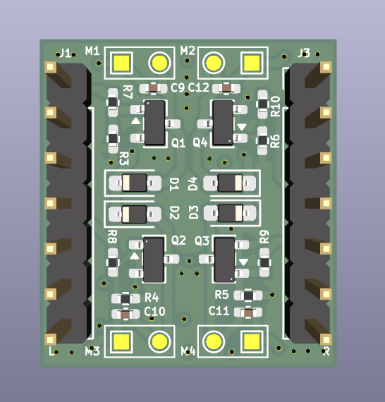
Motor side. The XIAO plugs into headers J1 and J3. M1–M4 are the motor pads.
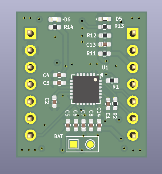
Sensor side. U1 is the MPU6050. The battery connects at the BAT pads.
| Part | Role |
|---|---|
| Seeed Studio XIAO ESP32-C3 | Flight controller. Plugs into J1 and J3. |
| MPU6050 (U1) | 6-axis gyro and accelerometer, I2C address 0x68 (AD0 held low). |
| 720 coreless motor × 4 | Brushed motors on M1, M2, M3, and M4. |
| AO3400A × 4 | Low-side MOSFET for each motor. |
| Schottky diode × 4 | Flyback diode across each motor (SOD-323). |
| ESP-Drone app | Phone app used to control the drone. |
Seat the XIAO with the USB end toward the 5V / D0 end of the headers (J3 pin 1 is 5V, J1 pin 1 is D0).
| XIAO pin | GPIO | Function |
|---|---|---|
| D0 | GPIO2 | Motor 1 gate (MOT1) |
| D3 | GPIO5 | Motor 2 gate (MOT2) |
| D9 | GPIO9 | Motor 3 gate (MOT3) |
| D10 | GPIO10 | Motor 4 gate (MOT4) |
| D4 | GPIO6 | MPU6050 SDA |
| D5 | GPIO7 | MPU6050 SCL |
| D7 | GPIO20 | MPU6050 interrupt |
| D2 | GPIO4 | Battery voltage sense |
| 3V3 | — | Sensor and gate pull-ups |
| GND | — | Common ground |
D9 is a boot strap pin. Its gate pull-down must leave the pin high enough at reset for the XIAO to start normally. Holding D9 low during reset puts the module into download mode.
D6 (GPIO21) is left free. It is the serial transmit pin and toggles while the chip boots.
Open ESC.kicad_pro in KiCad 10.
| Path | Contents |
|---|---|
ESC.kicad_sch | Schematic |
ESC.kicad_pcb | PCB layout |
libraries/ | XIAO ESP32-C3 and MPU6050 symbols and footprints |
GERBER/ | Fabrication Gerbers and drill files |
ESC-BOM.csv | Bill of materials |
ESC-all-pos.csv | Pick-and-place positions |
ESC-ESP32.step | 3D model of the board |
| Qty | Value | Footprint | References |
|---|---|---|---|
| 9 | 100nF | Capacitor_SMD:C_0402_1005Metric_Pad0.74x0.62mm_HandSolder | C5, C6, C7, C8, C9, C10, C11, C12, C13 |
| 6 | 10k | Resistor_SMD:R_0402_1005Metric_Pad0.72x0.64mm_HandSolder | R1, R2, R3, R4, R5, R6 |
| 5 | TestPoint_Small | TestPoint:TestPoint_Pad_1.0x1.0mm | TP1, TP3, TP5, TP7, TP9 |
| 5 | TestPoint_Small | TestPoint:TestPoint_Pad_D1.0mm | TP2, TP4, TP6, TP8, TP10 |
| 4 | 100R | Resistor_SMD:R_0402_1005Metric_Pad0.72x0.64mm_HandSolder | R7, R8, R9, R10 |
| 4 | AO3400A | Package_TO_SOT_SMD:SOT-23 | Q1, Q2, Q3, Q4 |
| 4 | SS14 | Diode_SMD:D_SOD-323_HandSoldering | D1, D2, D3, D4 |
| 2 | 0.1uF | Capacitor_SMD:C_0402_1005Metric_Pad0.74x0.62mm_HandSolder | C2, C4 |
| 2 | 1.5k | Resistor_SMD:R_0402_1005Metric_Pad0.72x0.64mm_HandSolder | R13, R14 |
| 2 | 100k | Resistor_SMD:R_0402_1005Metric_Pad0.72x0.64mm_HandSolder | R11, R12 |
| 2 | Conn_01x07_Pin | Connector_PinHeader_2.54mm:PinHeader_1x07_P2.54mm_Vertical | J1, J3 |
| 2 | LED | LED_SMD:LED_0402_1005Metric_Pad0.77x0.64mm_HandSolder | D5, D6 |
| 1 | 100uF | Capacitor_SMD:C_0402_1005Metric_Pad0.74x0.62mm_HandSolder | C14 |
| 1 | 10nF | Capacitor_SMD:C_0402_1005Metric_Pad0.74x0.62mm_HandSolder | C3 |
| 1 | 2.2nF | Capacitor_SMD:C_0402_1005Metric_Pad0.74x0.62mm_HandSolder | C1 |
| 1 | MPU-6050 | Sensor_Motion:InvenSense_QFN-24_4x4mm_P0.5mm | U1 |
It measures 19.8 × 21.9 mm and has 4 copper layers, 1.6 mm thick.
51 parts, built around the MPU-6050, AO3400A and SS14. The full list of its parts is on this page, with links to each part's symbol and footprint where PCBKit's library has them.
From the Adi1011-Data/ESP-Drone repository on GitHub, at the commit this page was made from: the board is hardware/PCB/ESC/ESC.kicad_pcb and its schematic hardware/PCB/ESC/ESC.kicad_sch. PCBKit opens the board in the browser, with nothing to install.
Its repository states no licence, so its author keeps all rights: ask Adi1011-Data before reusing the design.

angelowickramasinghe/Project-Drone
AeroFC-1S 1S brushed micro-quad flight controller (KiCad) — schematic, PCB, Gerbers, LCSC BOM

kokhaie/Smart-Refrigerator-Demo
The KiCad-generated BOM is mirrored into the documentation site under docs/ so it can be published through GitHub Pages.


hackeriet/imponator
The MCU has a 100nF capacitor between VCC and GND. This is quite standard for MCUs and sensors, but to be sure, check the datasheet.