2 layers79 × 60 mm
 adasbl/main-controller-pcb
Custom PCB for an autonomous wheeled robot
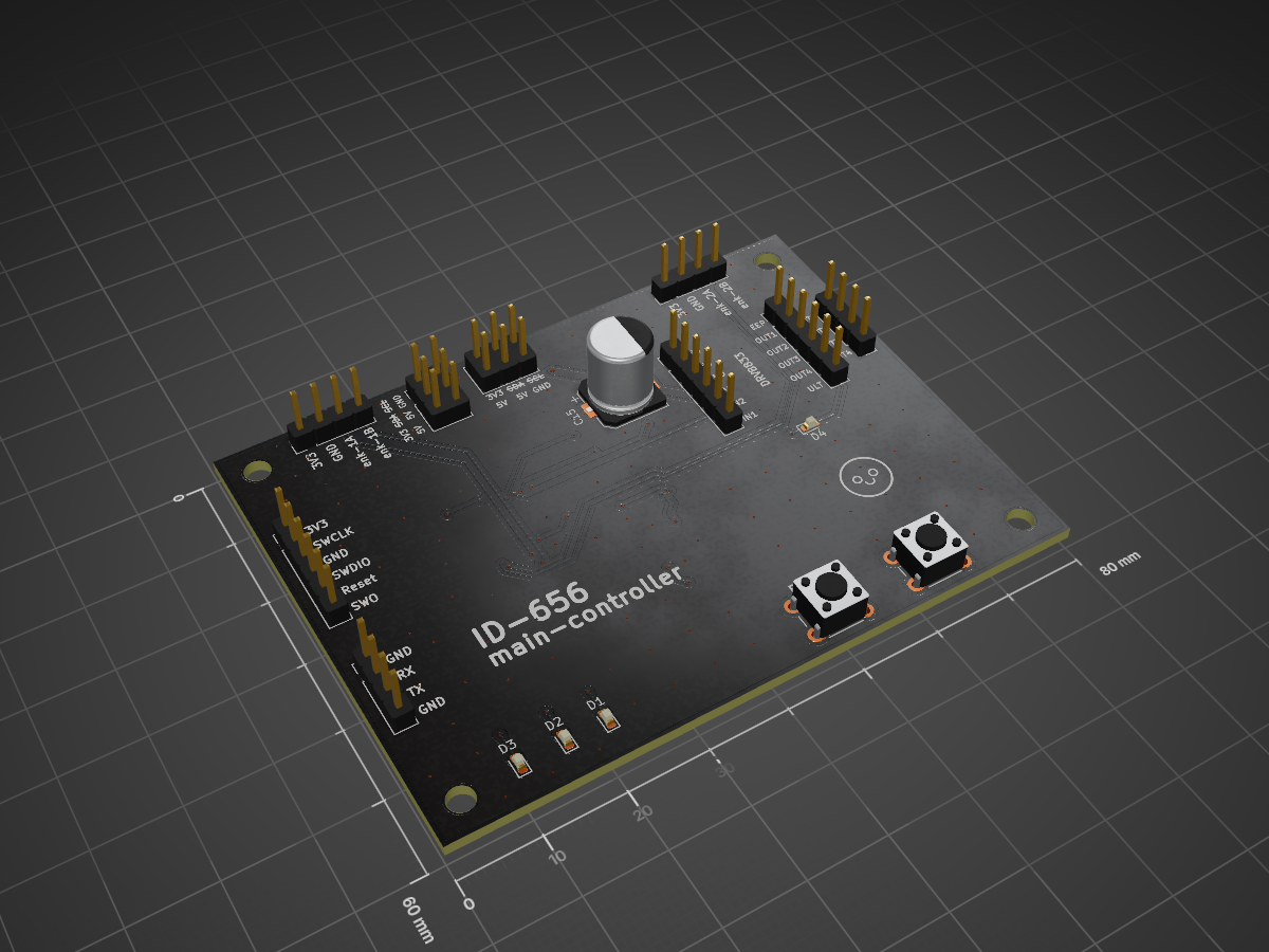
Pg id656 is an open-source printed circuit board by adasbl, from the adasbl/main-controller-pcb repository on GitHub. It is a 2-layer board of 80 × 60 mm with 47 parts on 76 nets, routed with 316 tracks and 142 vias.
It is built around the STM32L476RGT6, DI62063.3S2 and LSM6DSV16XTR. Its parts include 16 capacitors, 9 resistors, 9 connectors, 4 diodes and 2 ICs. It belongs with the STM32 boards of this library.


Custom PCB controller board for an autonomous wheeled robot featuring STM32L476RG
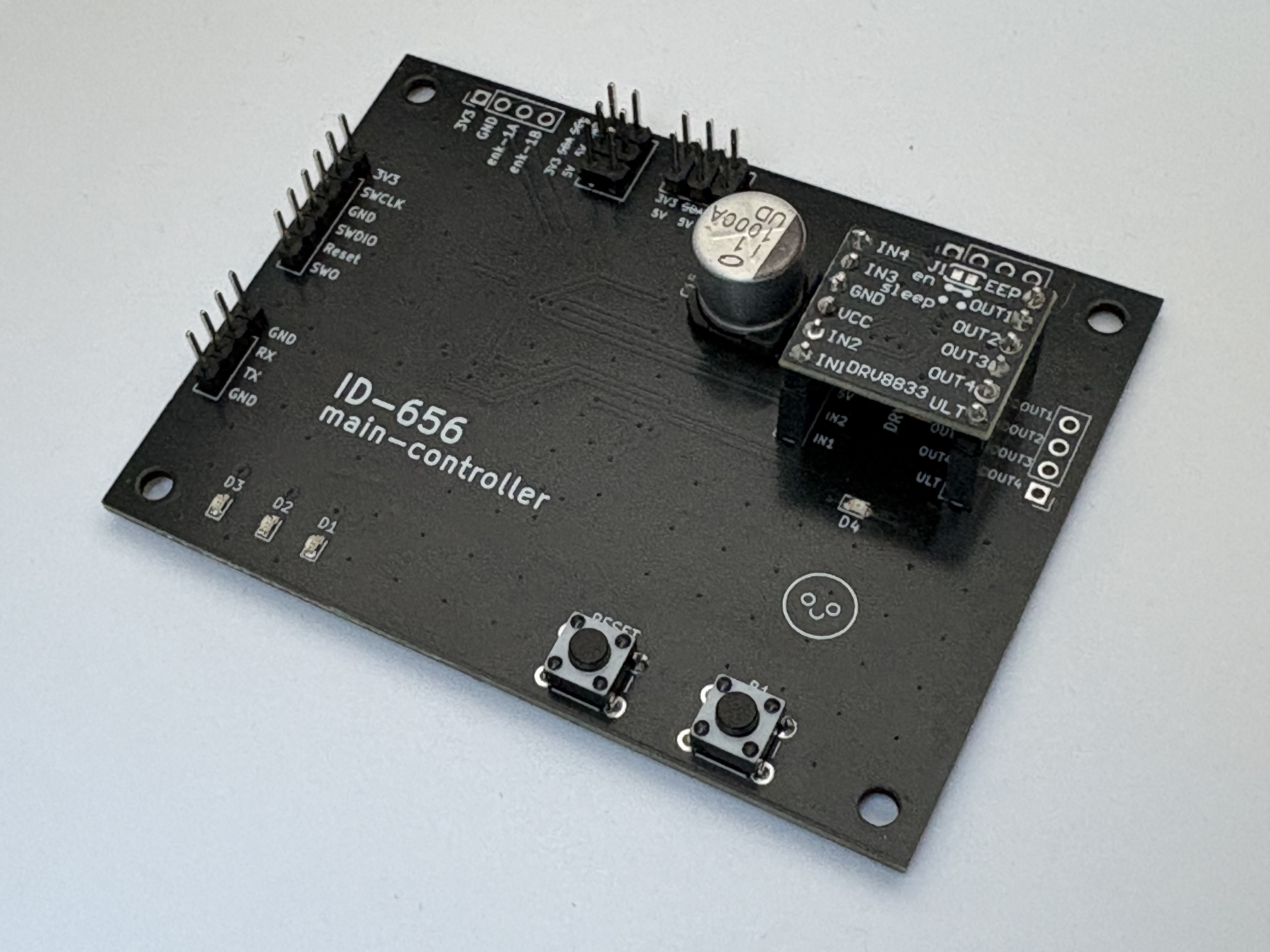
nFAULT pin (signals overcurrent, thermal shutdown, or undervoltage conditions).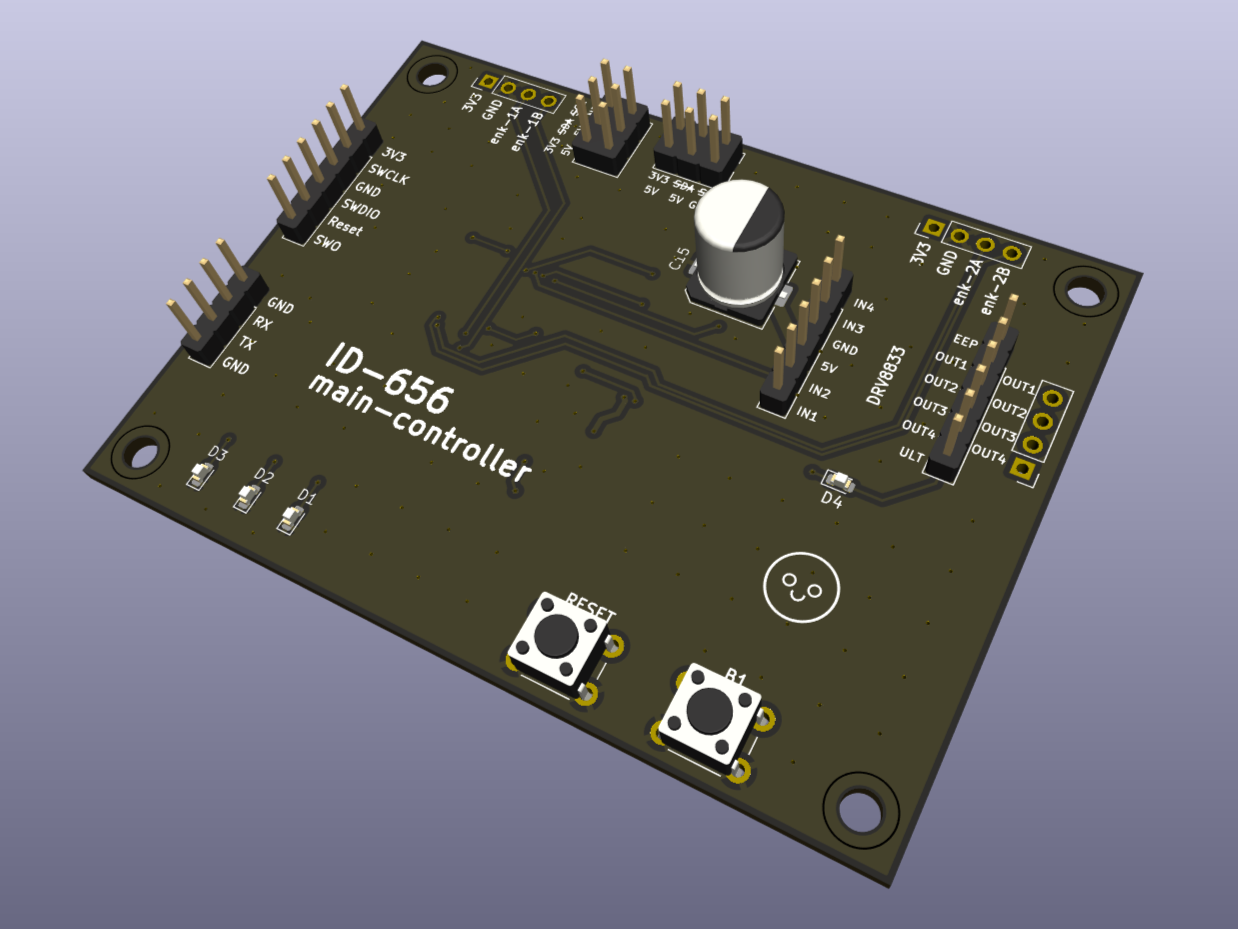
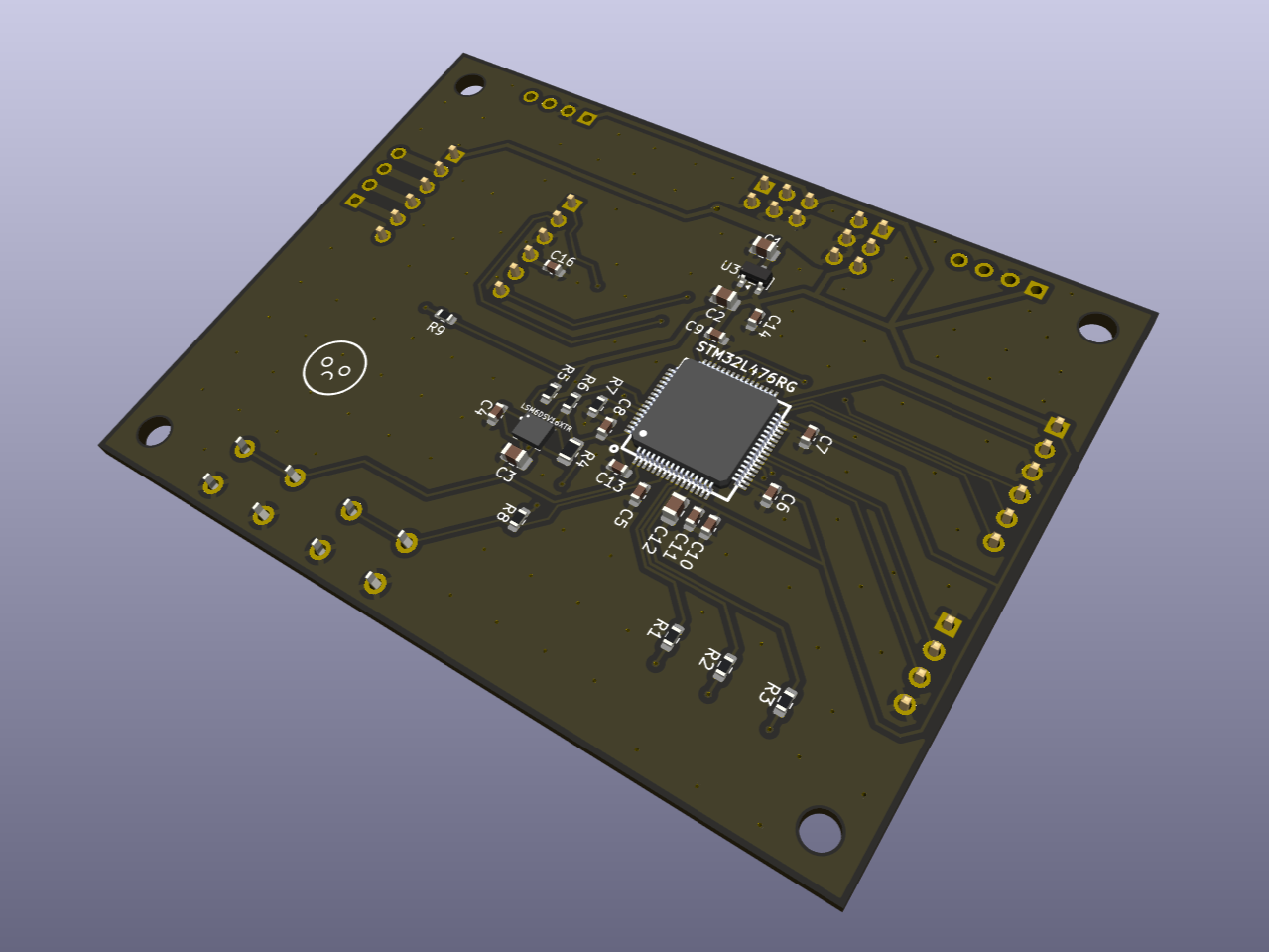
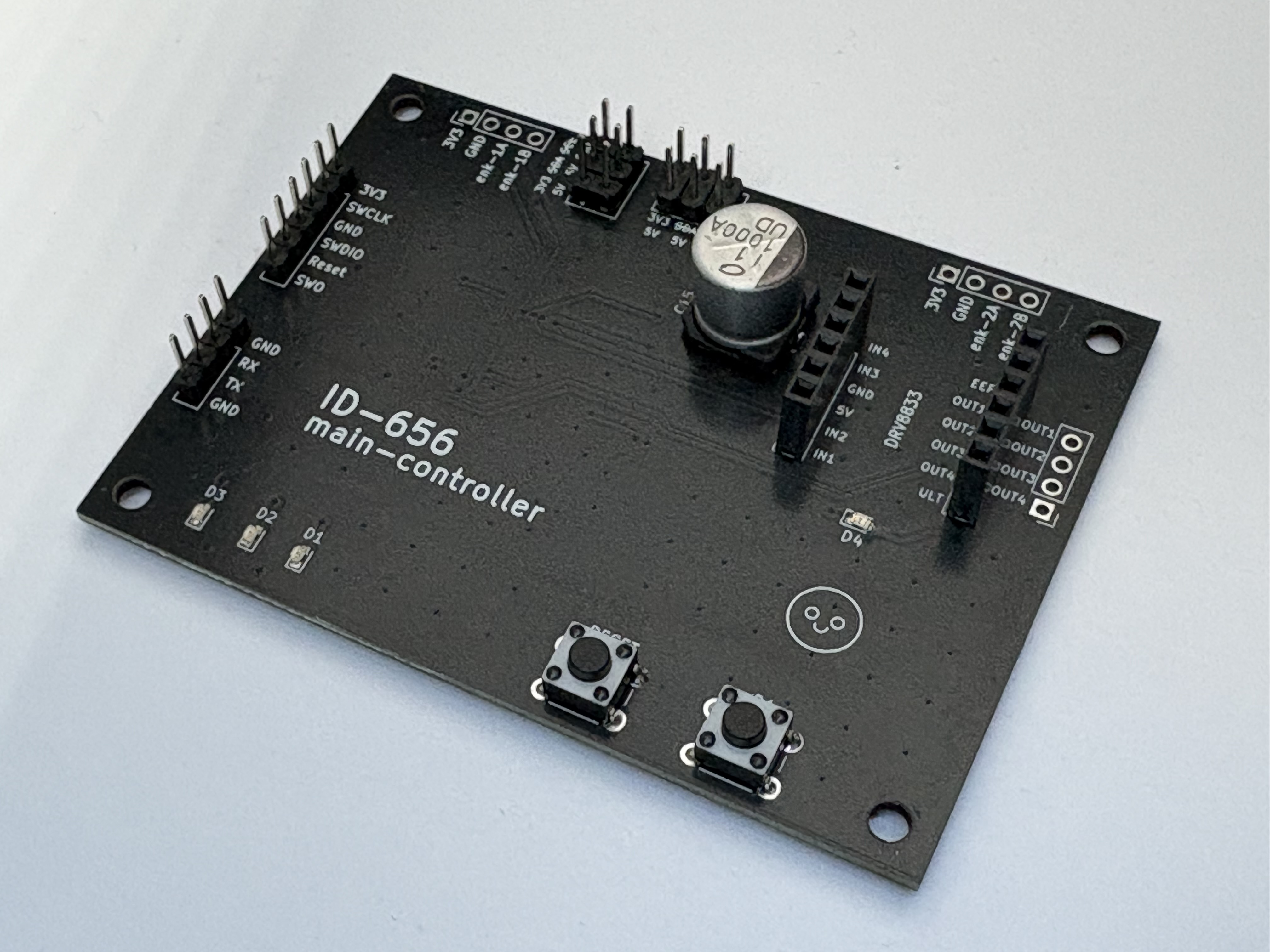
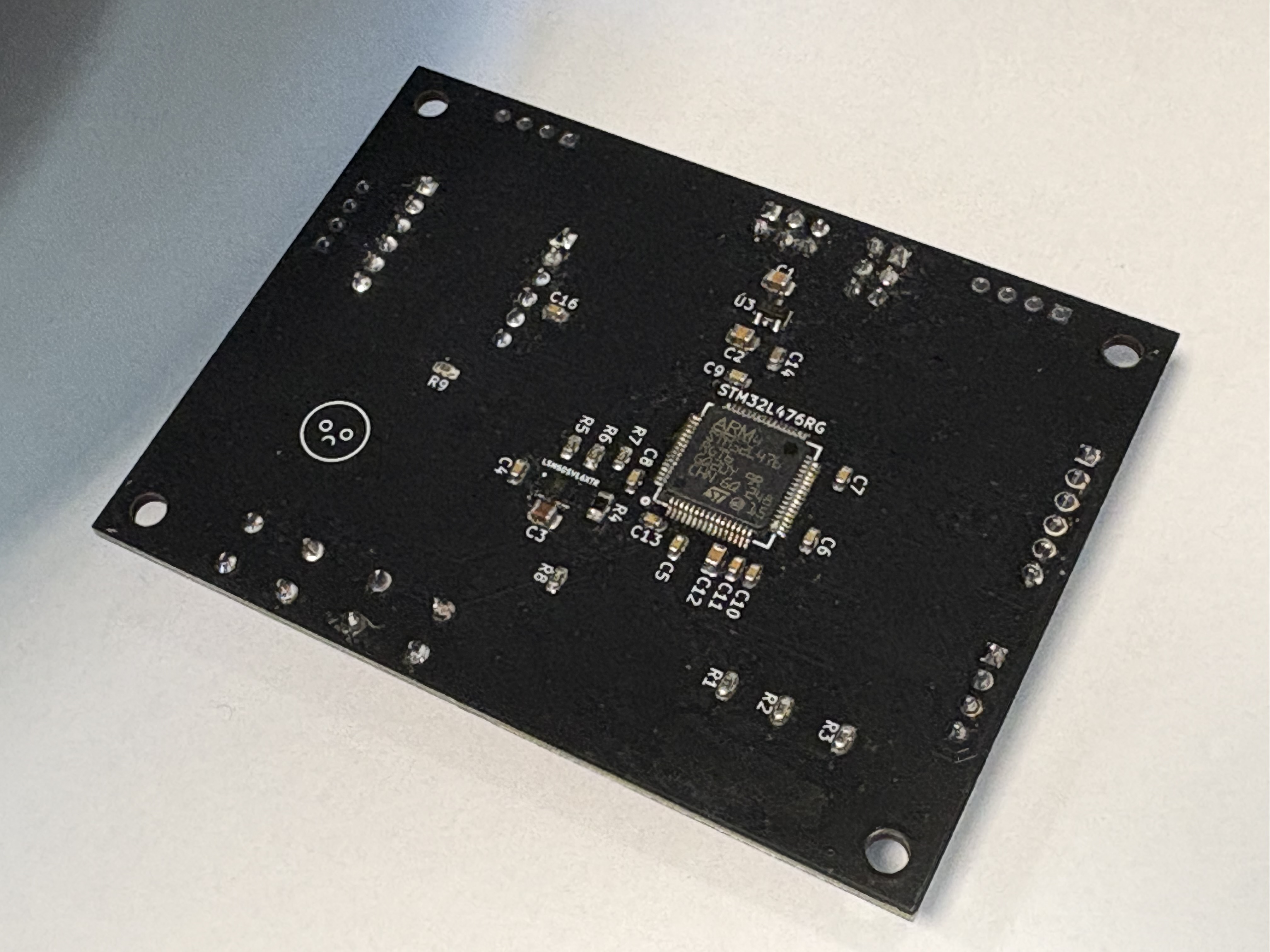
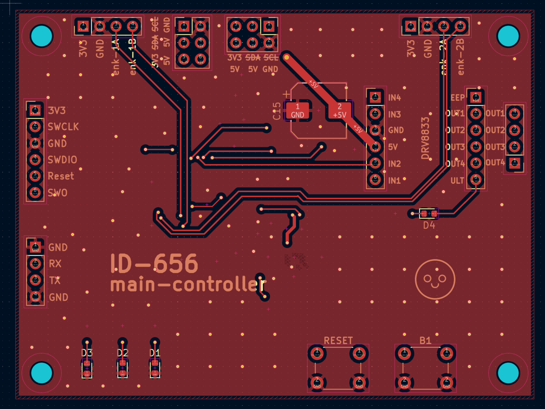
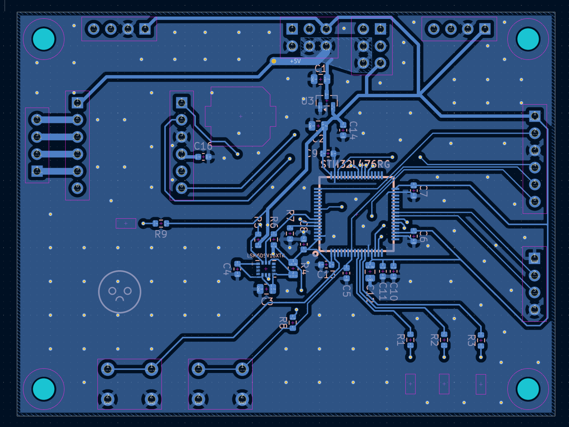
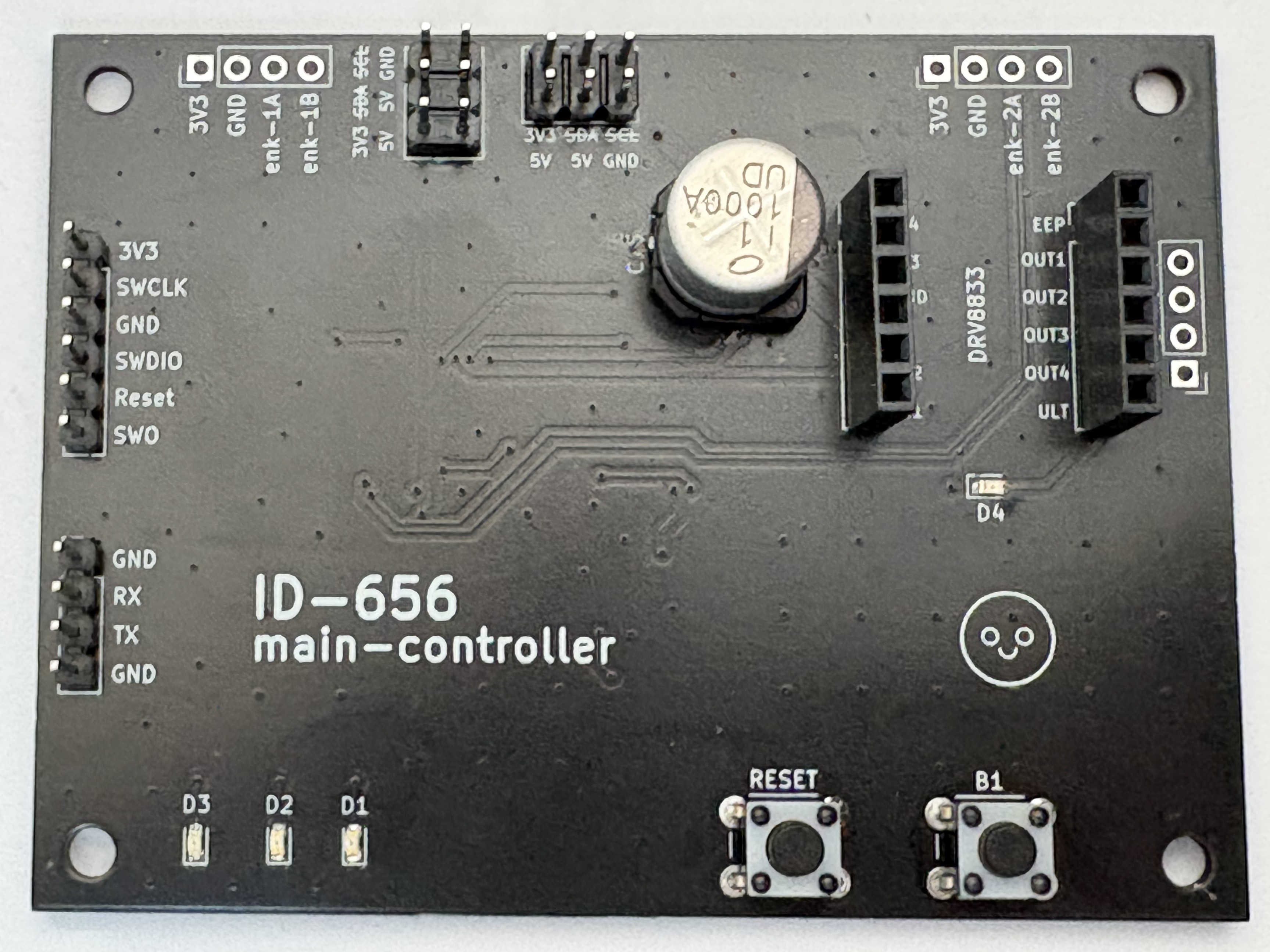
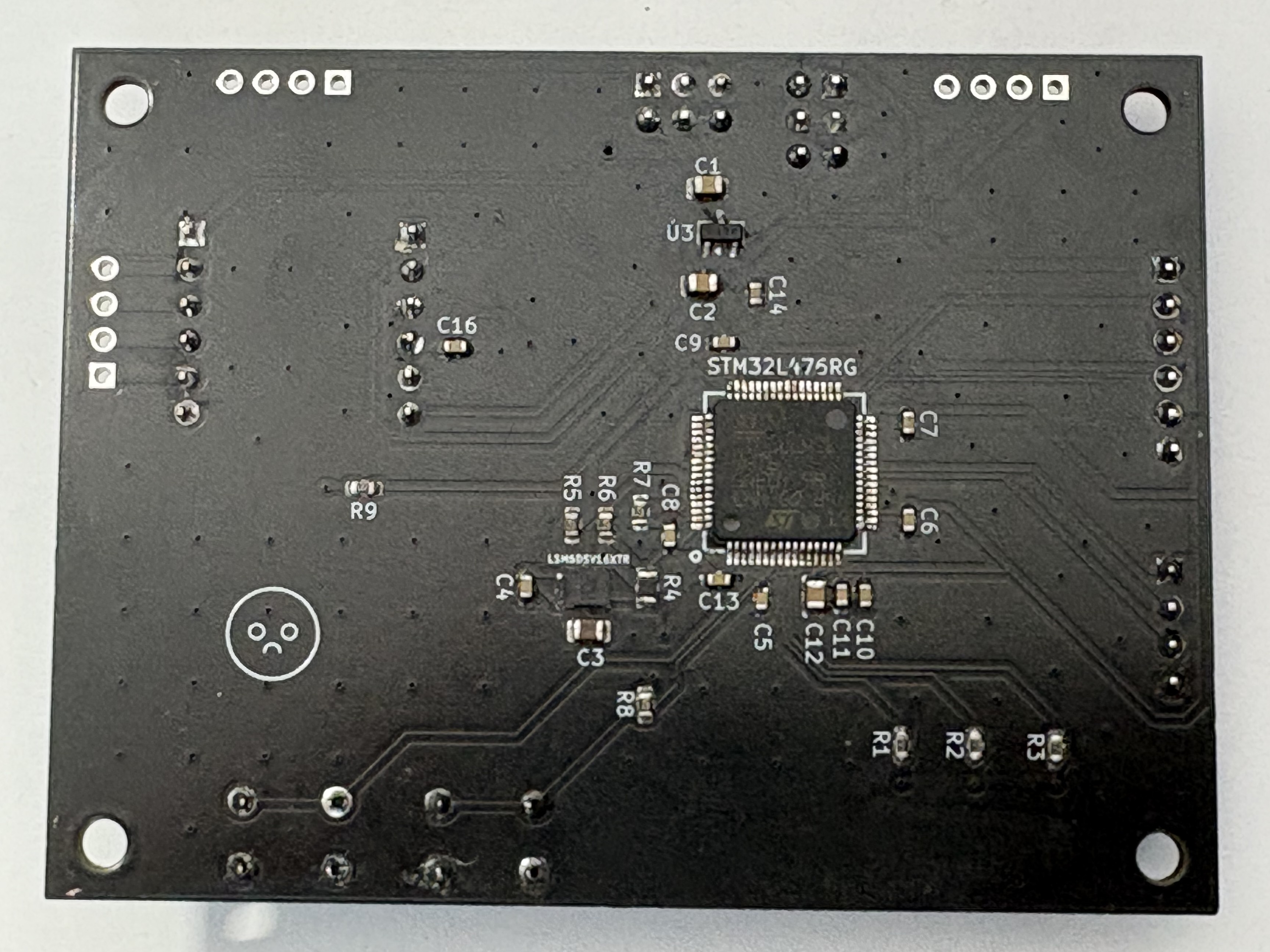
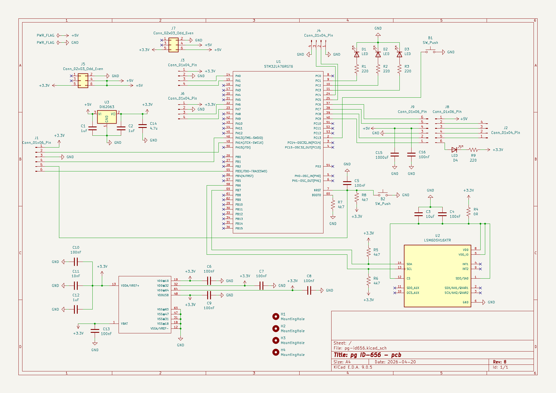
3Dmodels/ – 3D STEP/STL models.gerbers/ – Production-ready Gerber and drill files.images/ – 3D renders, schematic exports, and photos.KiCad-files/ – KiCad project source files (.kicad_pro, .kicad_sch, .kicad_pcb).id-656-pcb_v8.pdf – PDF export of the PCB layout.id-656-schematics_v8.pdf – PDF export of the schematic diagram.| Qty | Value | Footprint | References |
|---|---|---|---|
| 9 | 100nF | Capacitor_SMD:C_0603_1608Metric | C4, C5, C6, C7, C8, C9, C10, C13, C16 |
| 4 | 220 | Resistor_SMD:R_0603_1608Metric | R1, R2, R3, R9 |
| 4 | 4k7 | Resistor_SMD:R_0603_1608Metric | R5, R6, R7, R8 |
| 4 | Conn_01x04_Pin | Connector_PinHeader_2.54mm:PinHeader_1x04_P2.54mm_Vertical | J2, J3, J4, J6 |
| 4 | LED | LED_SMD:LED_0603_1608Metric | D1, D2, D3, D4 |
| 4 | MountingHole | MountingHole:MountingHole_3.2mm_M3_DIN965 | H1, H2, H3, H4 |
| 3 | 1uF | Capacitor_SMD:C_0805_2012Metric | C1, C2, C12 |
| 3 | Conn_01x06_Pin | Connector_PinHeader_2.54mm:PinHeader_1x06_P2.54mm_Vertical | J1, J8, J9 |
| 2 | Conn_02x03_Odd_Even | Connector_PinHeader_2.54mm:PinHeader_2x03_P2.54mm_Vertical | J5, J7 |
| 2 | SW_Push | Button_Switch_THT:SW_PUSH_6mm | B1, RESET |
| 1 | 0R | Resistor_SMD:R_0805_2012Metric | R4 |
| 1 | 1000uF | Capacitor_SMD:CP_Elec_8x10 | C15 |
| 1 | 10nF | Capacitor_SMD:C_0603_1608Metric | C11 |
| 1 | 10uF | Capacitor_SMD:C_0805_2012Metric | C3 |
| 1 | 4.7u | Capacitor_SMD:C_0603_1608Metric | C14 |
| 1 | DI62063 | Package_TO_SOT_SMD:SOT-23 | U3 |
| 1 | LSM6DSV16XTR | Moje_Elementy:XDCR_LSM6DSV16XTR | LSM6DSV16XTR |
| 1 | STM32L476RGT6 | Moje_Elementy:LQFP-64_10X10_MM | U1 |
It measures 80 × 60 mm and has 2 copper layers, 1.6 mm thick.
47 parts, built around the STM32L476RGT6, DI62063.3S2 and LSM6DSV16XTR. The full list of its parts is on this page, with links to each part's symbol and footprint where PCBKit's library has them.
From the adasbl/main-controller-pcb repository on GitHub, at the commit this page was made from: the board is KiCad-files/pg-id656.kicad_pcb and its schematic KiCad-files/pg-id656.kicad_sch. PCBKit opens the board in the browser, with nothing to install.
Its repository states no licence, so its author keeps all rights: ask adasbl before reusing the design.

PandoroML/LOAF
LOAF (Local Observations and Atmospheric Forecasting) is an open source hyperlocal weather forecasting combining gridded forecasts with local station observations using machine learning and open-source hardware.


lucasnoce/IC-LevelSensor_v2
Water level sensor with NBIoT data transmission

abendezu10/PulseWatch
Developed a fully functional smartwatch using an STM32 microcontroller, featuring real-time heart rate monitoring.
