Skip to the content
PCBKitNew board
4 layers101 × 53.3 mmHackboard, the printed circuit board in 3D

An extended Arduino Uno clone based on the STM32L476RG

Size
101 × 53.3 mm
Copper layers
4
Thickness
1.61 mm
Parts
65
Nets
83
Pads
316
Tracks, vias
565, 69
Pours
7
Routed
Yes
KiCad
KiCad 8.0 (file 20240108)
Created
1 Aug 2024
Updated
3 Sep 2024

Overview

Hackboard is an open-source printed circuit board by AdamTuraj, from the AdamTuraj/Hackboard repository on GitHub, published under the GPL-3.0 licence. It is a 4-layer board of 101 × 53.3 mm with 65 parts on 83 nets, routed with 565 tracks and 69 vias.

It is built around the STM32L476RGT6, MSD-1-A and AP7361C-33E, with the USBLC6-2SC6, CC0603KRX7R7BB105 and CRGCQ0603J220R among its other parts. Its parts include 20 capacitors, 14 resistors, 8 connectors, 6 diodes and 4 ICs. It belongs with the STM32 boards of this library.

Main components

12

README

README.md

Title Saying Hackboard

Every hardware hacker needs a development board. So why not make your own overkill one?

The Hackboard is a "one board fits (almost) all" development board with many useful features to ensure it works with all projects! Whether you need to drive a motor, listen through a microphone, play music on a speaker or use various peripherals, the Hackboard has you covered.

Running on Arduino or STM32CubeIDE, you can take full advantage of Hackboard due to its low learning curve. On top of all these features, it is super efficient and can easily run off a 9v battery for many hours. Still not interested. Get a larger overview of the features below!
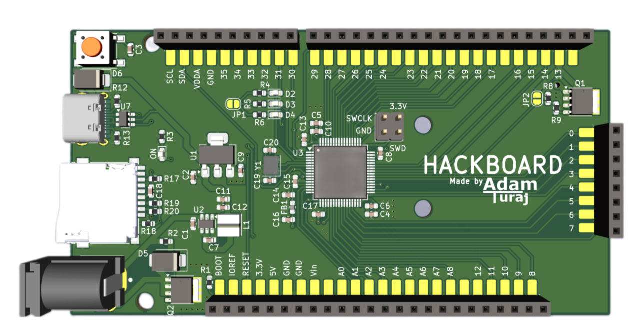
A Top 3d view of the hackboard

Here's a deeper dive into the features:

  • 80MHz Cortex M4 Core with 1 Mb of Flash and 128 Kb of SRAM
  • Abilitiy to run on a 9v battery for around 150 HOURS1
  • 45 GPIO pins
    • 2 SPI Interfaces2
    • 1 I2C Interface
    • 1 CAN Interface
    • 1 UART Interface
    • 18 PWM Pins
    • 9 ADC's (Analog pins)
    • 2 DAC's
    • 1 OPAmp
  • Arduino Uno Shield Compatible
  • Same hole arrangement as Arduino UNO3
  • Extended header pads for easy probing
  • Micro SD card slot
  • PWM Addressable MOSFET capable of powering up to 54W
  • 3 addressable LED's
  • Barrel jack supporting up to 32V at 54W
  • USB C port for flashing and power

Assembly

[!WARNING] This board CANNOT be assembled through JLCPCB due to many of the parts not being available at LCSC. Alternatives are using different PCB manufacturers or assembling it yourself

The BOM can be found in the production folder or the Digikey list here.

The extra MOSFET and related circuitry on pin 13 does not need to be soldered for the board to function (hence the DNP).

Jumpers

JP1 and JP2 are jumpers that can be soldered/desoldered to achieve certain functionality.

JP1 must be bridged to enable the addressable LED's. JP2 must be left unbridged if the MOSFET is soldered.

Work with Arduino

[!NOTE] You must have an STLink to continue. They can be bought standalone or with a Nucleo board

A more detailed guide will be written up shortly. For now you may use STM32Duino to make it work with Arduino.

Images

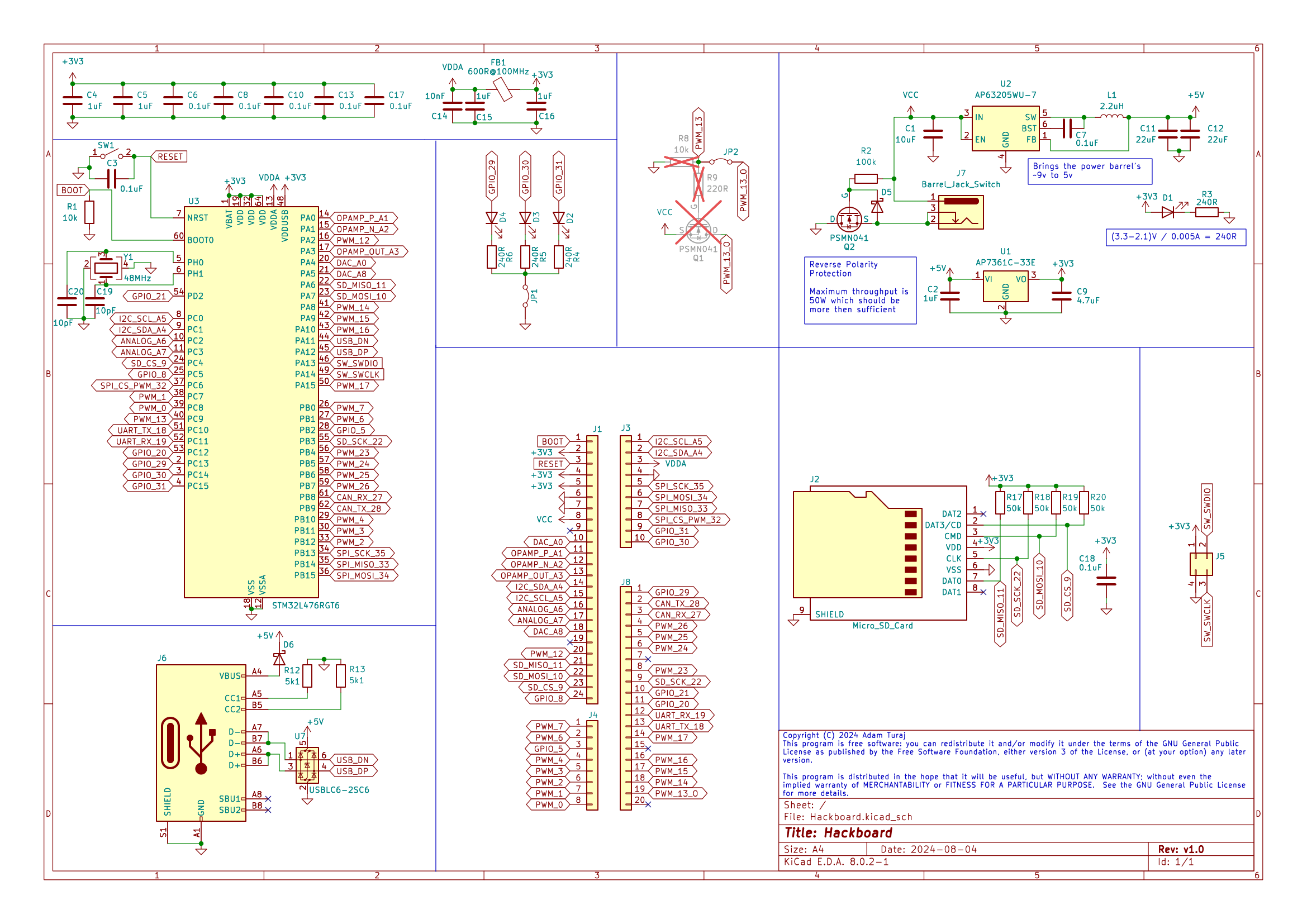
Schematic Schematic
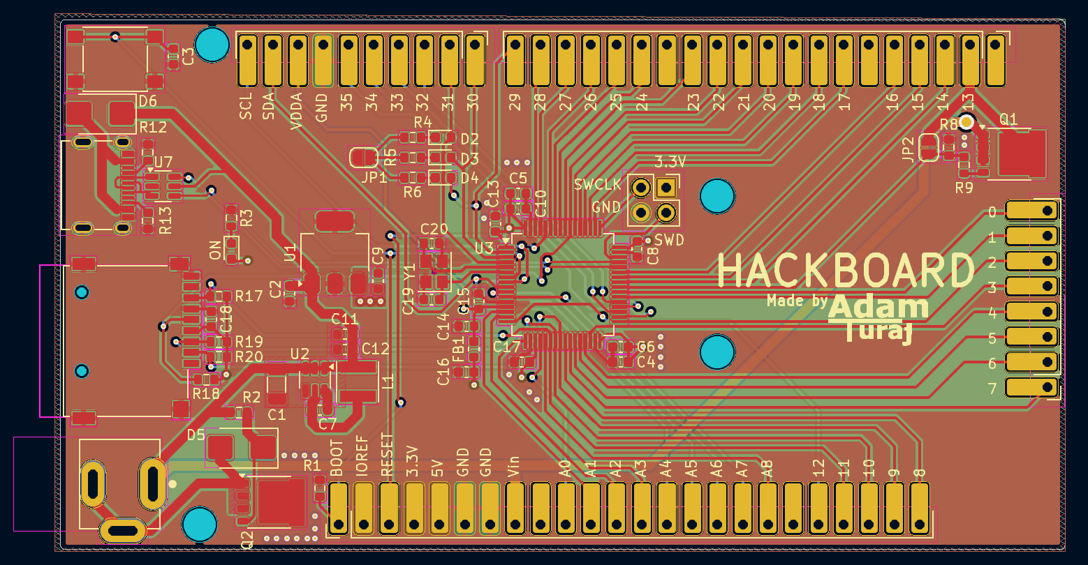
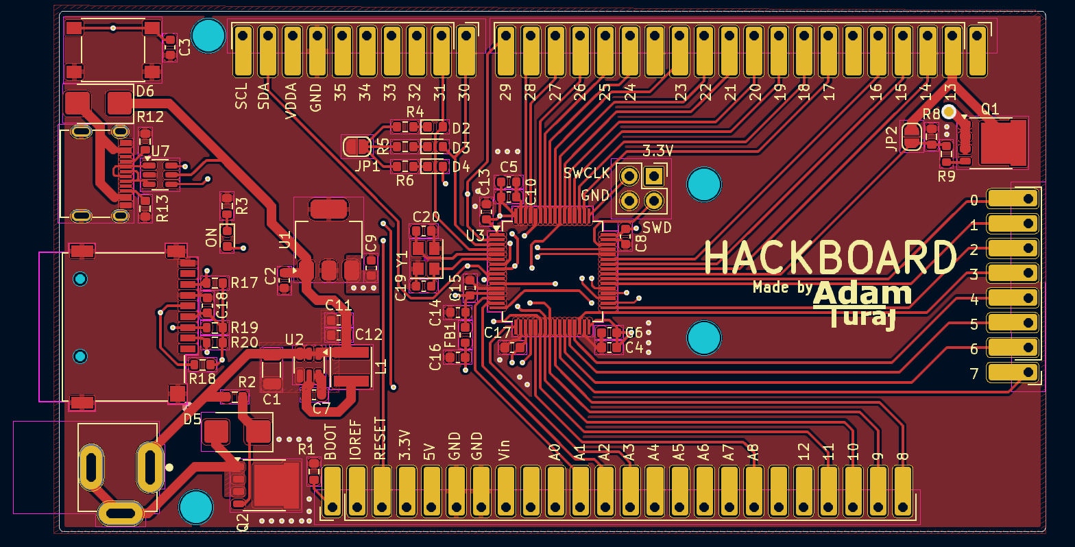
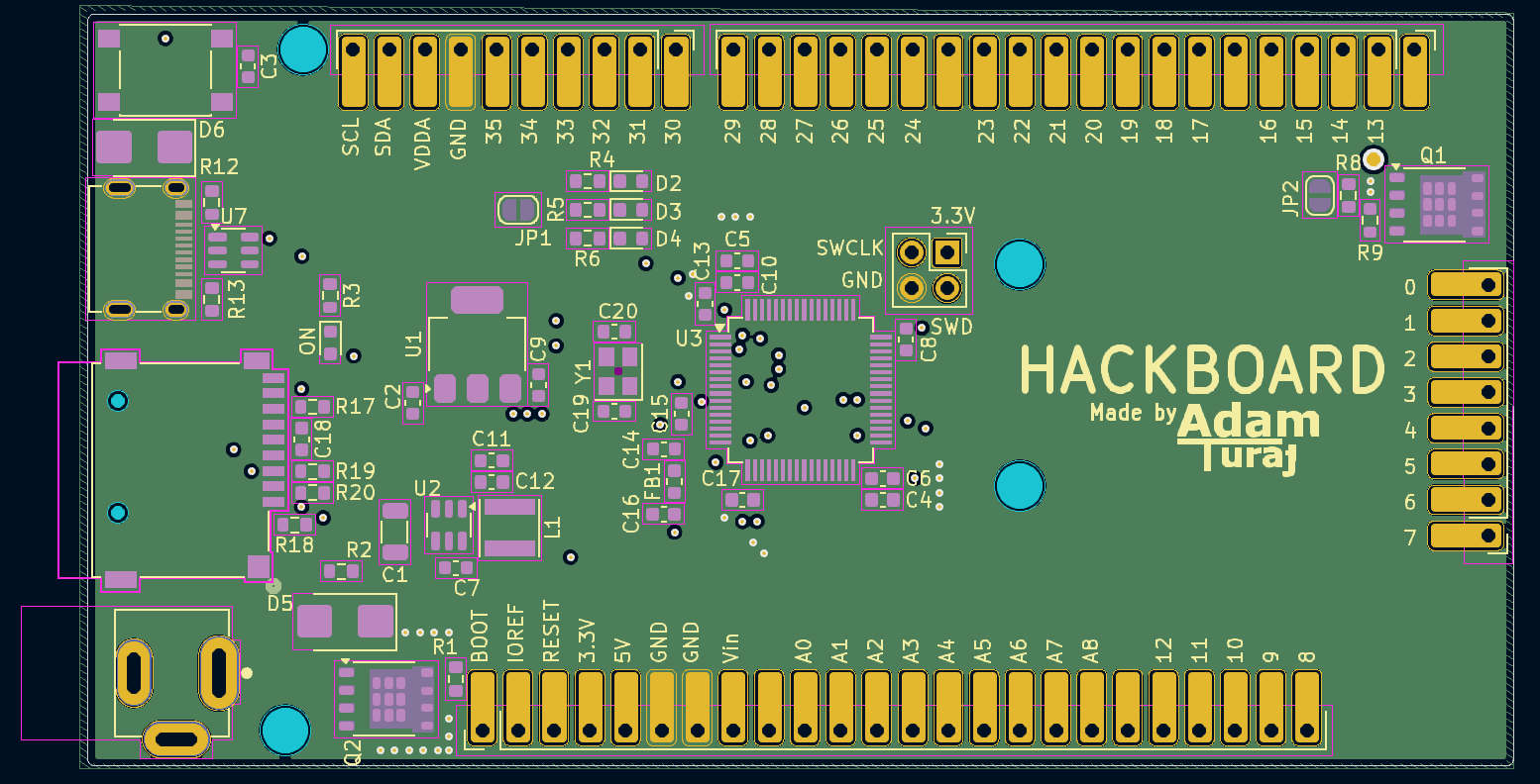
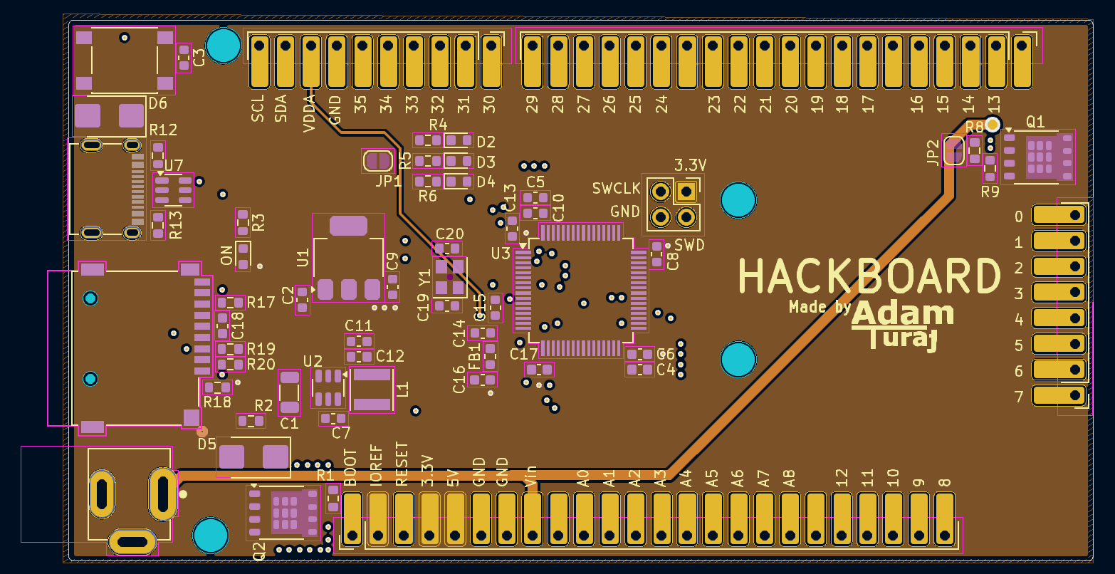
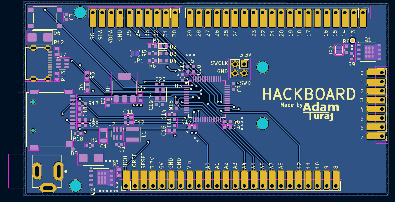
All Layers All PCB Layers

Top Layer (Signal / GND) Top PCB Layer

Second Layer (GND) Second PCB Layer

Third Layer (Power) Third PCB Layer

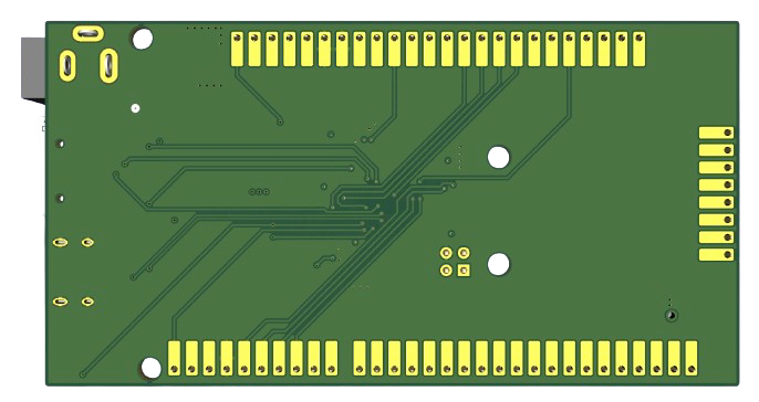
Bottom Layer (Signal / GND) Bottom PCB Layer

Bottom 3D View

Bottom 3D View

License

Hackboard is licensed under the GNU General Public License. See the full license text in LICENSE.

Footnotes

  1. This assumes you are running with 0 peripherals connected, and are using a Duracell 9v battery ↩

  2. Only one may be used when an SD card is in use. ↩

  3. The bottom right hole moved slightly up due to spacing issues. ↩

Parts

65
QtyValueFootprintReferences
80.1uFCapacitor_SMD:C_0603_1608MetricC3, C6, C7, C8, C10, C13, C17, C18
51uFCapacitor_SMD:C_0603_1608MetricC2, C4, C5, C15, C16
4240RResistor_SMD:R_0603_1608MetricR3, R4, R5, R6
450kResistor_SMD:R_0603_1608MetricR17, R18, R19, R20
4LEDLED_SMD:LED_0603_1608MetricD1, D2, D3, D4
4MountingHoleMountingHole:MountingHole_3.2mm_M3H1, H2, H3, H4
210kResistor_SMD:R_0603_1608MetricR1, R8
210pFCapacitor_SMD:C_0603_1608MetricC19, C20
222uFCapacitor_SMD:C_0603_1608MetricC11, C12
25k1Resistor_SMD:R_0603_1608MetricR12, R13
2D_SchottkyDiode_SMD:D_SMBD5, D6
2Jumper_2_BridgedJumper:SolderJumper-2_P1.3mm_Open_RoundedPad1.0x1.5mmJP1, JP2
2PSMN041Package_TO_SOT_SMD:LFPAK56Q1, Q2
1100kResistor_SMD:R_0603_1608MetricR2
110nFCapacitor_SMD:C_0603_1608MetricC14
110uFCapacitor_SMD:C_1206_3216MetricC1
12.2uHInductor_SMD:L_Vishay_IFSC-1515AH_4x4x1.8mmL1
1220RResistor_SMD:R_0603_1608MetricR9
14.7uFCapacitor_SMD:C_0603_1608MetricC9
148MHzOscillator:Oscillator_SMD_Abracon_ASE-4Pin_3.2x2.5mmY1
1600R@100MHzInductor_SMD:L_0603_1608MetricFB1
1AP63205WU-7Package_TO_SOT_SMD:TSOT-23-6U2
1AP7361C-33EPackage_TO_SOT_SMD:SOT-223-3_TabPin2U1
1Barrel_Jack_SwitchConnector_BarrelJack:CUI_PJ-002AHJ7
1Conn_01x08Headers:PinSocket_1x08_P2.54mm_VerticalJ4
1Conn_01x10Headers:PinSocket_1x10_P2.54mm_VerticalJ3
1Conn_01x20Headers:PinSocket_1x20_P2.54mm_VerticalJ8
1Conn_01x24Headers:PinSocket_1x24_P2.54mm_VerticalJ1
1Conn_02x02_Counter_ClockwiseConnector_PinHeader_2.54mm:PinHeader_2x02_P2.54mm_VerticalJ5
1LOGOSymbol:logoG***
1Micro_SD_CardConnector_Card:CONN9_MSD-1_CUDJ2
1STM32L476RGT6Package_QFP:LQFP-64_10x10mm_P0.5mmU3
1SW_SPSTButton_Switch_SMD:SW_SPST_PTS645SW1
1USBLC6-2SC6Package_TO_SOT_SMD:SOT-23-6U7
1USB_C_Receptacle_USB2.0_16PConnector_USB:USB_C_Receptacle_Amphenol_GSB1C4J6

Questions

How big is the Hackboard PCB?

It measures 101 × 53.3 mm and has 4 copper layers, 1.61 mm thick.

What parts does the Hackboard use?

65 parts, built around the STM32L476RGT6, MSD-1-A, AP7361C-33E and USBLC6-2SC6. The full list of its parts is on this page, with links to each part's symbol and footprint where PCBKit's library has them.

Where can I download the Hackboard KiCad files?

From the AdamTuraj/Hackboard repository on GitHub, at the commit this page was made from: the board is Hackboard.kicad_pcb and its schematic Hackboard.kicad_sch. PCBKit opens the board in the browser, with nothing to install.

Can I use the Hackboard design in my own project?

Its repository publishes it under the GPL-3.0 licence: you may reuse it on that licence's terms (keep the author's notice, and for a copyleft licence share your changes alike).

Similar boards

  • 4 layers80 × 40 mmAudio latency tester board, the printed circuit board in 3D

    Audio latency tester board

    antmicro/audio-latency-tester-board

    This project contains open hardware design files for an audio latency processing board. The system allows driving an external speaker and collecting audio samples from a pair of PDM or I2S microphones.

    240 parts1Apache-2.0
  • 2 layers82.5 × 82.5 mmEPS V1, the printed circuit board in 3D

    EPS V1

    BrownSpaceEngineering/PVDX-EPS_V1

    Avionics files related to new overhauled EPS schematics, pcb design, and documentation

    197 parts
  • 2 layersRF Tin Can, the printed circuit board in 3D

    RF Tin Can

    ECE411-Fall2021-Group4/RF-Tin-Can

    LoFi Walkie Talkie

    89 partsGPL-3.0
  • 4 layers202.3 × 90 mmMythra psu, the printed circuit board in 3D

    Mythra psu

    bad-alloc-heavy-industries/Mythra

    45 parts7BSD-3-Clause
  • 2 layers54.9 × 66.5 mmKiCad Schematic, the printed circuit board in 3D

    KiCad Schematic

    DDeGonge/Shuffle-o-matic

    Open Source Card Shuffler

    51 parts106MIT
  • 2 layers90.4 × 89.6 mmPolicyBadge25, the printed circuit board in 3D

    PolicyBadge25

    mosfet0/policyatdc33

    Policy@DEF CON 33 Badge collaboration

    68 partsGPL-3.0
  • 2 layers60 × 50 mmStarfish, the printed circuit board in 3D

    Starfish

    paeber/led-driver-starfish

    ESP32 based LED driver designed for use with ESPHome

    81 partsMIT