2 layers89 × 100 mm
Hub16
joshajohnson/Hub16
A macro pad with 16 keys, two rotary encoders, a four port USB hub, and plenty of LEDs!
132 parts388

 acornejo/ergo-k33b2
56-key split/unified ortholinear keyboard with an integrated trackpad
Ergo k33b is an open-source printed circuit board by acornejo, from the acornejo/ergo-k33b repository on GitHub, published under the MIT licence. It is a 2-layer board of 330 × 130.8 mm with 132 parts on 79 nets, routed with 1,101 tracks and 13 vias.
Its parts include 56 diodes and 56 switches. It belongs with the keyboards and input boards of this library.
A 56-key split/unified ortholinear keyboard with an integrated trackpad, designed in Ergogen and routed manually in KiCad.
The ergo-k33b is a custom keyboard PCB featuring a symmetric 6×4 column-staggered matrix on each half, palm modifier keys, a 3-key thumb cluster per side, and an optional 65mm×50mm Azoteq TPS65 trackpad mounted in the center of the board.
The board uses a single unified PCB that mirrors the left and right halves — no split cable required.
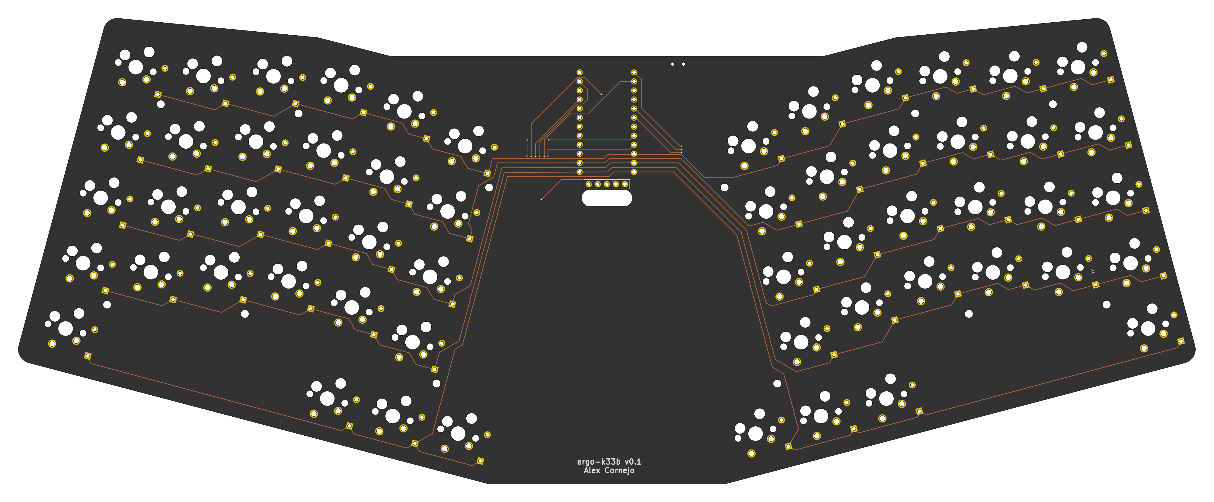
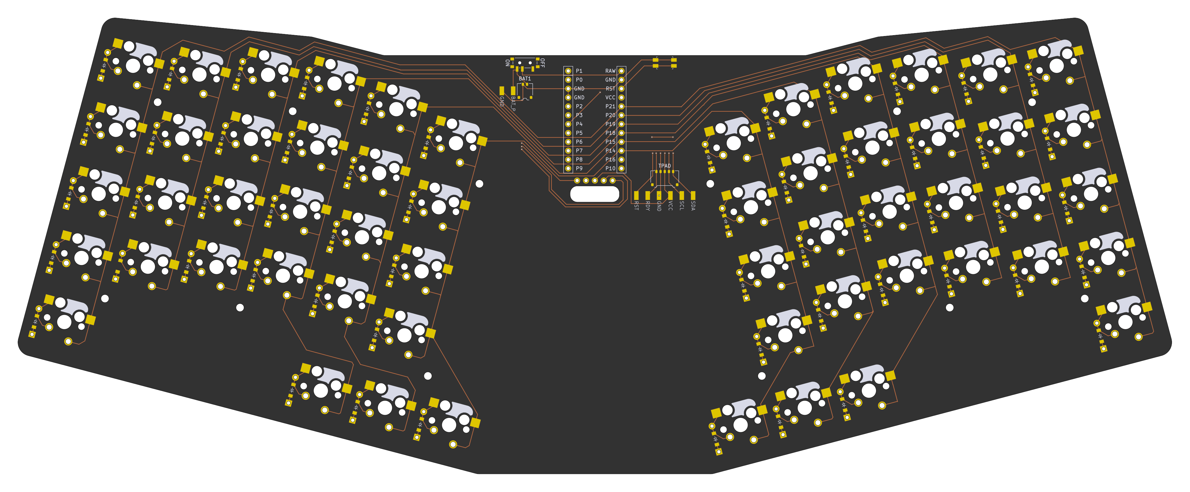
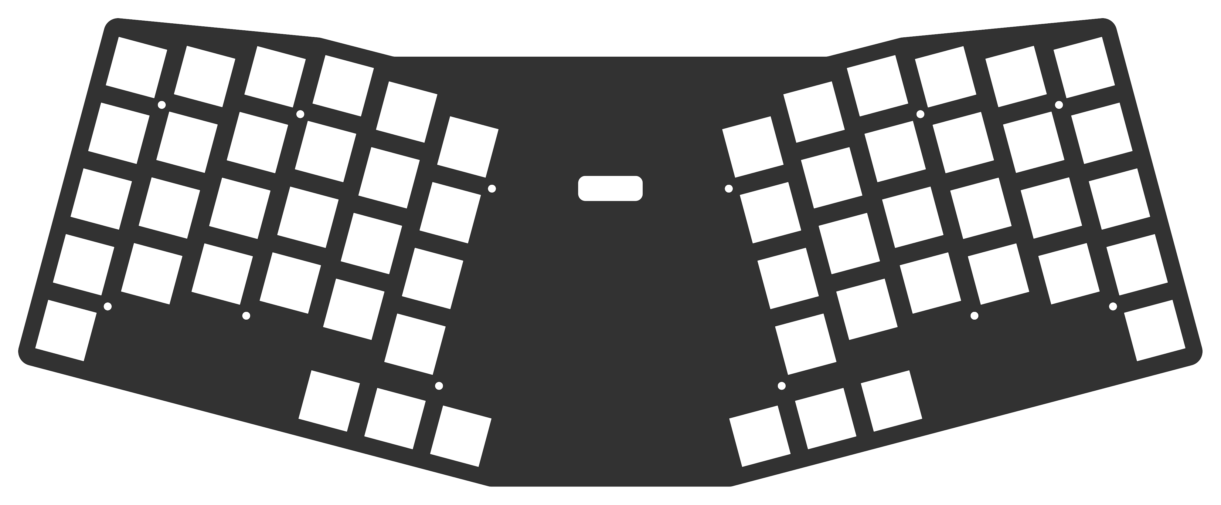
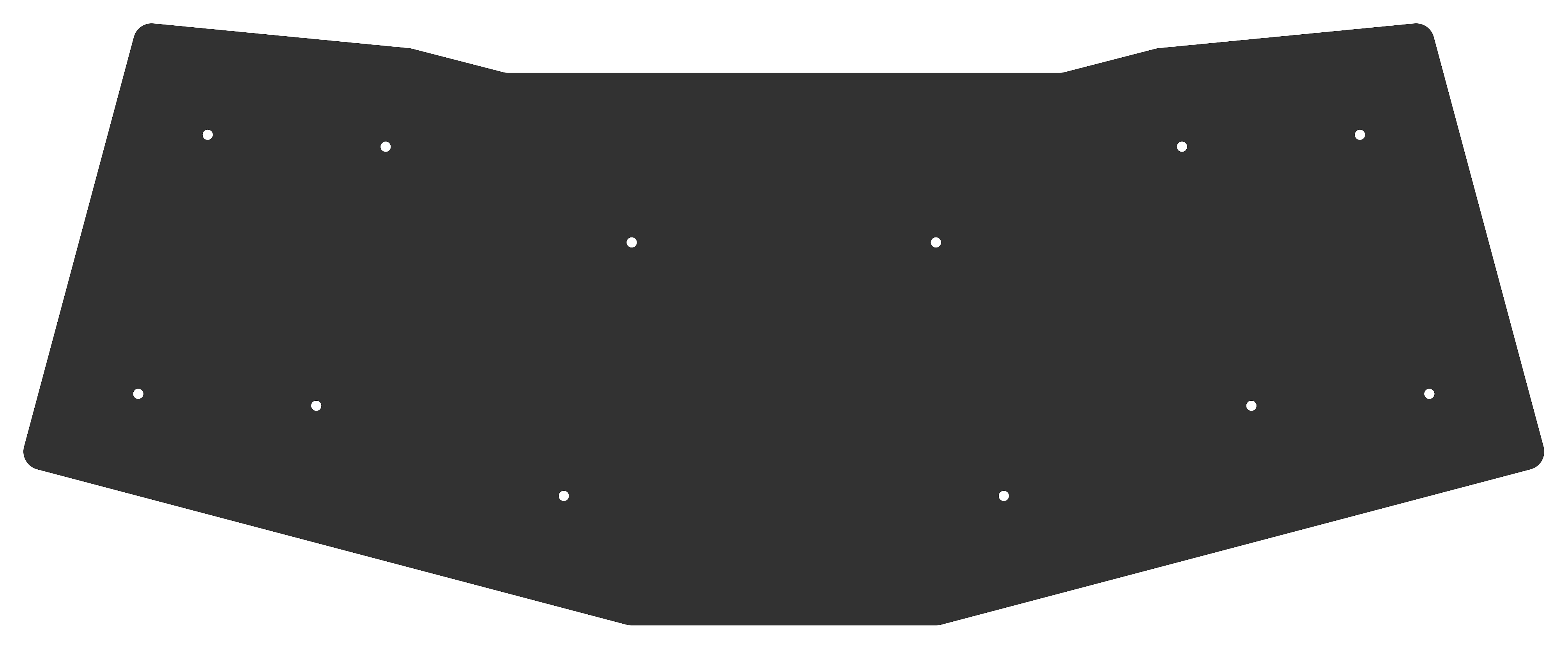
| Component | Part | Notes |
|---|---|---|
| MCU | Nice!Nano (nRF52840 SuperMini) | Mounted on the back, centered between halves |
| Display | Nice!View | Optional; SPI via P1/P2/P3 |
| Trackpad | Azoteq TPS65 (65mm × 50mm) | Optional; I²C via P4/P5, ready signal P0 |
| Switches | Cherry MX 5-pin | Hotswap and solder options |
| Diodes | SOD-123 (SMD) + THT | Both footprints populated; one per key |
| Battery connector | Molex Pico EZmate 1×2 | Also exposes BAT_P / GND solder pads as an alternative |
| Trackpad connector | Molex Pico EZmate 1×5 | Also exposes RST / RDY / GND / VCC / SCL / SDA solder pads as an alternative |
| Power switch | SMD side-mount | On the back of the board |
| Reset button | SMD side-mount | On the back of the board |
Both the battery and trackpad use Molex Pico EZmate connectors rather than the more common JST-PH standard. Pico EZmate has a lower profile (1.48 mm mated height vs. 3.0 mm for JST-PH), which keeps the overall board assembly thinner. Each connector also has corresponding solder pad footprints on the PCB, so you can wire the battery or trackpad directly without a connector if preferred.
The PCB was designed using Ergogen v4.2 to generate the board outline, key positions, and component footprints from ergogen/config.yaml. Routing was done manually in KiCad. The freerouting scripts in this repo are provided for experimentation only.
Three PCBs are generated from the Ergogen config:
| PCB | Description |
|---|---|
main_board | The keyboard PCB with all switches, diodes, MCU, and connectors |
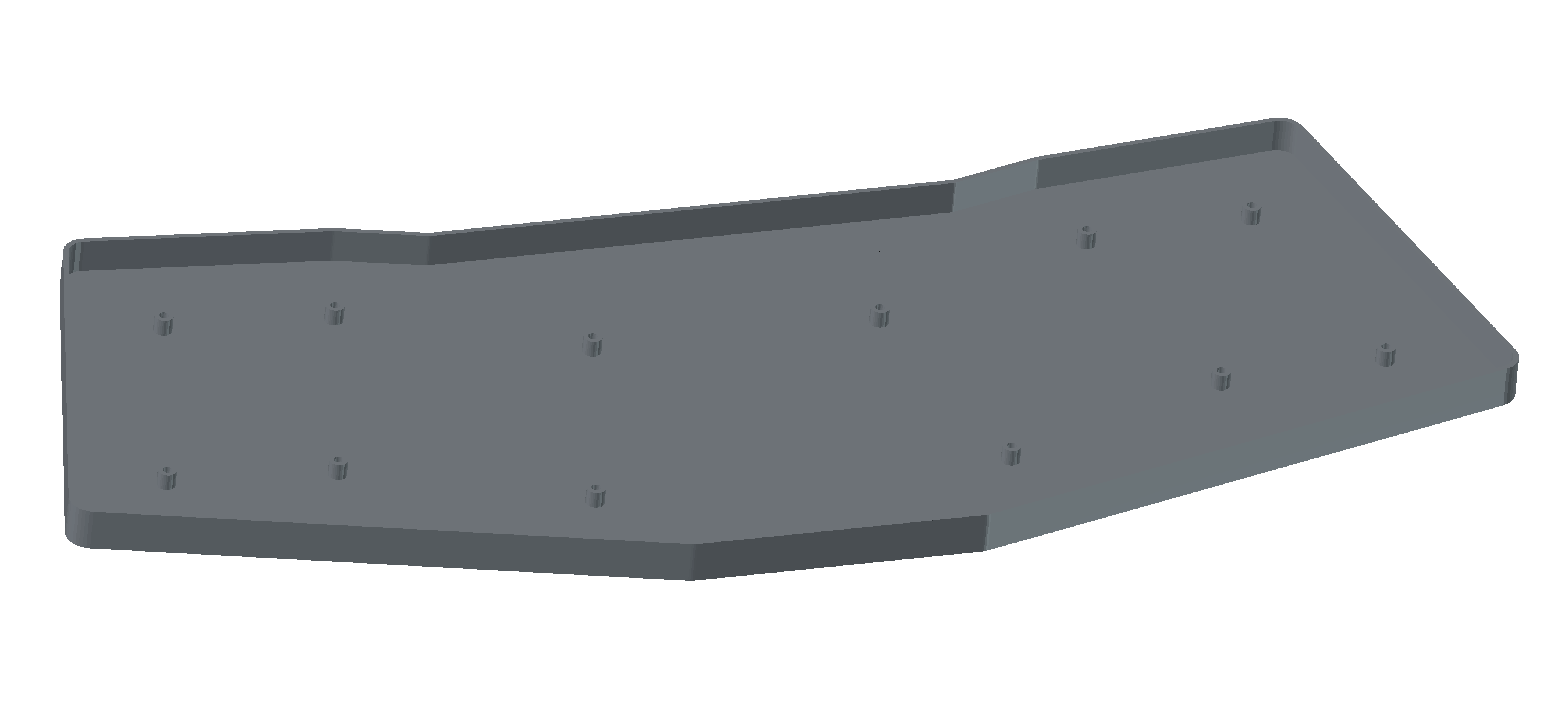
frontplate | Switch plate with key cutouts and screw holes |
backplate | Bottom cover plate with screw holes |
A bottom_case 3D model (STL) is also generated from the Ergogen outlines using OpenJSCAD.
| Pin | Function |
|---|---|
| P21 | Column: outer |
| P20 | Column: pinky |
| P19 | Column: ring |
| P18 | Column: middle |
| P15 | Column: index |
| P14 | Column: inner |
| P10 | Row: bottom |
| P8 | Row: home |
| P16 | Row: top |
| P7 | Row: num |
| P9 | Row: thumb cluster |
| P13 | Row: palm keys |
| P0 | Trackpad RDY |
| P4 | Trackpad SCL (I²C) |
| P5 | Trackpad SDA (I²C) |
| P6 | Trackpad RST |
| P1 | Nice!View CS |
| P2 | Nice!View MOSI |
| P3 | Nice!View SCK |
ergogen/
  config.yaml       # Full Ergogen board definition
output/
  pcbs/             # Generated KiCad PCB files
  cases/            # Generated OpenJSCAD and STL files
  outlines/         # Generated outline DXFs
  gerbers/          # Fabrication outputs
scripts/
  boards.kibot.yaml # KiBot config for main board exports
  default.kibot.yaml# KiBot config for plate exports
  export_dsn.py     # Export KiCad PCB to Specctra DSN
  import_ses.py     # Import Specctra SES back to KiCad
  freerouting.rules # Freerouting design rules
main_board.kicad_pcb # Hand-routed main board (source of truth)
build.sh            # Docker-based build script (KiBot + Freerouting)
images/ # Board rendersnpm install
npm run buildThis runs Ergogen to regenerate all PCBs, outlines, and case STL files under output/.
./build.shThis uses Docker to:
Note: The hand-routed
main_board.kicad_pcbat the repo root is the production board. The autorouted output is for experimentation only.
npm run cleanThe Nice!Nano runs ZMK Firmware. Create a ZMK config repo with a shield definition matching the matrix pinout above.
See LICENSE.
| Qty | Value | Footprint | References |
|---|---|---|---|
| 56 | ceoloide:diode_tht_sod123 | D1, D2, D10, D11, D12, D13, D14, D15, D16, D17, D18, D19, D20, D21, D22, D23 +40 | |
| 28 | custom_lib:switch_mx2 | S29, S30, S31, S32, S33, S34, S35, S36, S37, S38, S39, S40, S41, S42, S43, S44 +12 | |
| 28 | ceoloide:switch_mx | S1, S2, S10, S11, S12, S13, S14, S15, S16, S17, S18, S19, S20, S21, S22, S23 +12 | |
| 12 | ceoloide:mounting_hole_npth | MH1, MH2, MH3, MH4, MH5, MH6, MH7, MH8, MH9, MH10, MH11, MH12 | |
| 2 | pads | BAT_PADS1, TPAD_PADS1 | |
| 1 | ceoloide:power_switch_smd_side | PWR1 | |
| 1 | ceoloide:reset_switch_smd_side | RST1 | |
| 1 | Connector_Molex:Molex_Pico-EZmate_78171-0002_1x02-1MP_P1.20mm_Vertical | BAT1 | |
| 1 | ceoloide:display_nice_view | DISP1 | |
| 1 | Connector_Molex:Molex_Pico-EZmate_78171-0005_1x05-1MP_P1.20mm_Vertical | TPAD | |
| 1 | ceoloide:mcu_supermini_nrf52840 | MCU1 |
joshajohnson/Hub16
A macro pad with 16 keys, two rotary encoders, a four port USB hub, and plenty of LEDs!


slu4coder/Minimal-64-Home-Computer
Legacy: Full TTL-only home computer with VGA and PS/2 and twice the processing power of a Commodore 64


RIP-Felix/MEGA-AV-main
Timeline of events: ACE9921 & Villahed94 developed the original Mega Amp 1.0. Inception for a mod board that combines the Mega Amp with an RGB video amplifier was Bob from RetroRGB's idea.

mirdej/synkie
The Synkie is a modular open source analog video processor, developed by Michael Egger, Max Egger and Flo Kaufmann
It measures 330 × 130.8 mm and has 2 copper layers, 1.6 mm thick.
132 parts. The full list of its parts is on this page, with links to each part's symbol and footprint where PCBKit's library has them.
From the acornejo/ergo-k33b repository on GitHub, at the commit this page was made from: the board is main_board.kicad_pcb. PCBKit opens the board in the browser, with nothing to install.
Its repository publishes it under the MIT licence: you may reuse it on that licence's terms (keep the author's notice, and for a copyleft licence share your changes alike).