2 layers80 × 50 mm

 timbk/BetaBoard85
A simple and low cost particle detector for teaching
BetaBoard is an open-source printed circuit board by timbk, from the timbk/BetaBoard repository on GitHub, published under the BSD-2-Clause licence. It is a 2-layer board of 65 × 45 mm with 132 parts on 93 nets, routed with 634 tracks and 201 vias.
It is built around the RP2040, LM358 and W25Q128JVSIQ, with the ZMM3V3-M, 1N5819WS and 轻触开关3X4X2 among its other parts. Its parts include 44 resistors, 41 capacitors, 23 diodes, 7 ICs and 6 connectors. It belongs with the RP2040 boards of this library.


A particle detector built for cost-effectiveness when ordered at O(100) pieces.
The detector concept is adapted from the DIY Particle Detector Project by Oliver Keller.
| Revision 1 | Revision 2 |
|---|---|
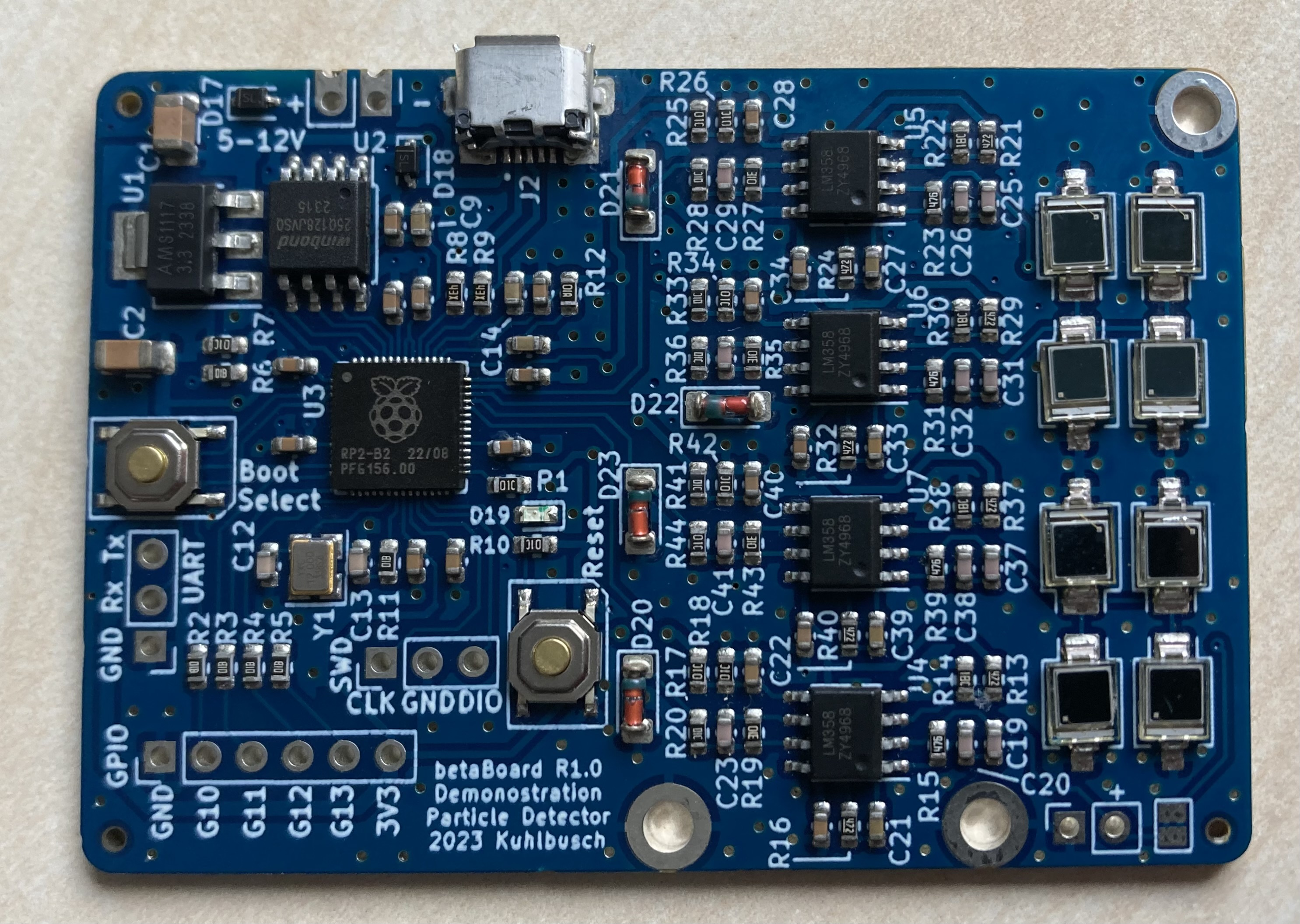 | 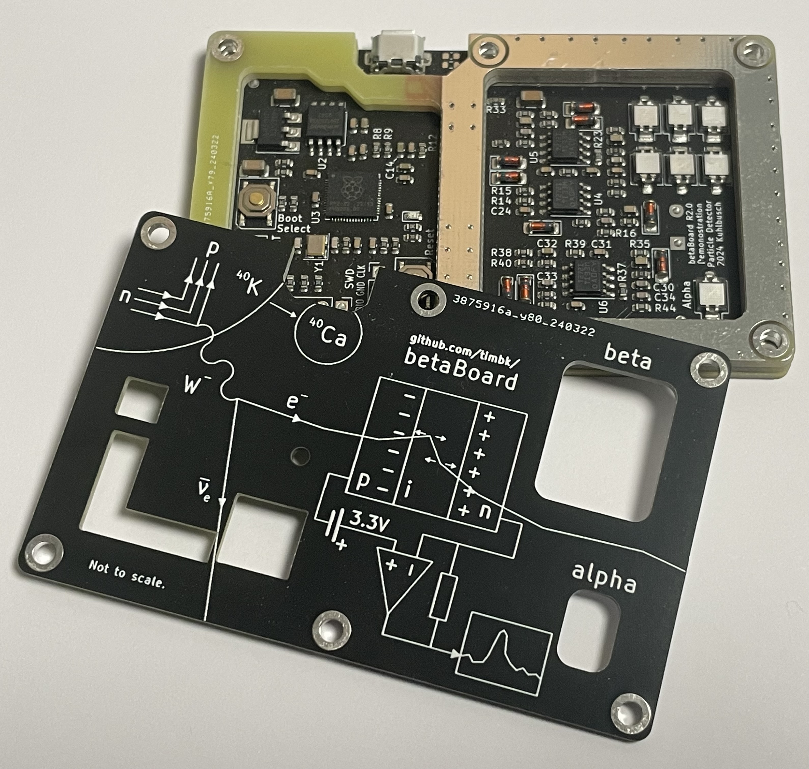 |
| Schematic Layout | Schematic Layout Component Positions |
| Initial protoype: Working with adjustemtns to a few component values. Requires a lot of electrical and conductive tape to assemble. Designed for 16 diodes with the option to measure coincidences. | Streamlined redesign. Mainly adding a PCB casing to block light and radio imission. Attempting to add a simple alpha particle detector channel by stripping the isolation off of a diode (not successfull yet). Single channel with 6 diodes in parallel. Using additional ADC channels with less gain for debugging and potential experiments with scintillators. |
T T <block_index> <timestamp_us> <overflow> # <sample_0> <sample_1> .. <sample_N>
block_index: uint16_t, mainly relevant for debuggingtimestamp_us: uint64_t, Trigger point timestamp in micro seconds since start of the measurementoverflow: bool, set to 1 if an overflow happend prior to this samplesample_n: int16_t, samples from the triggered waveform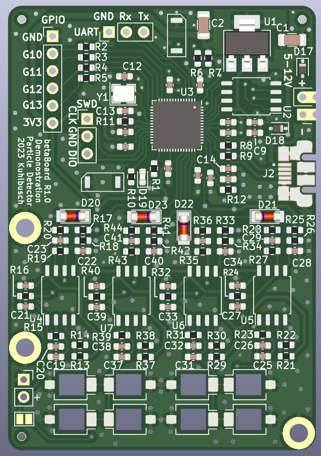
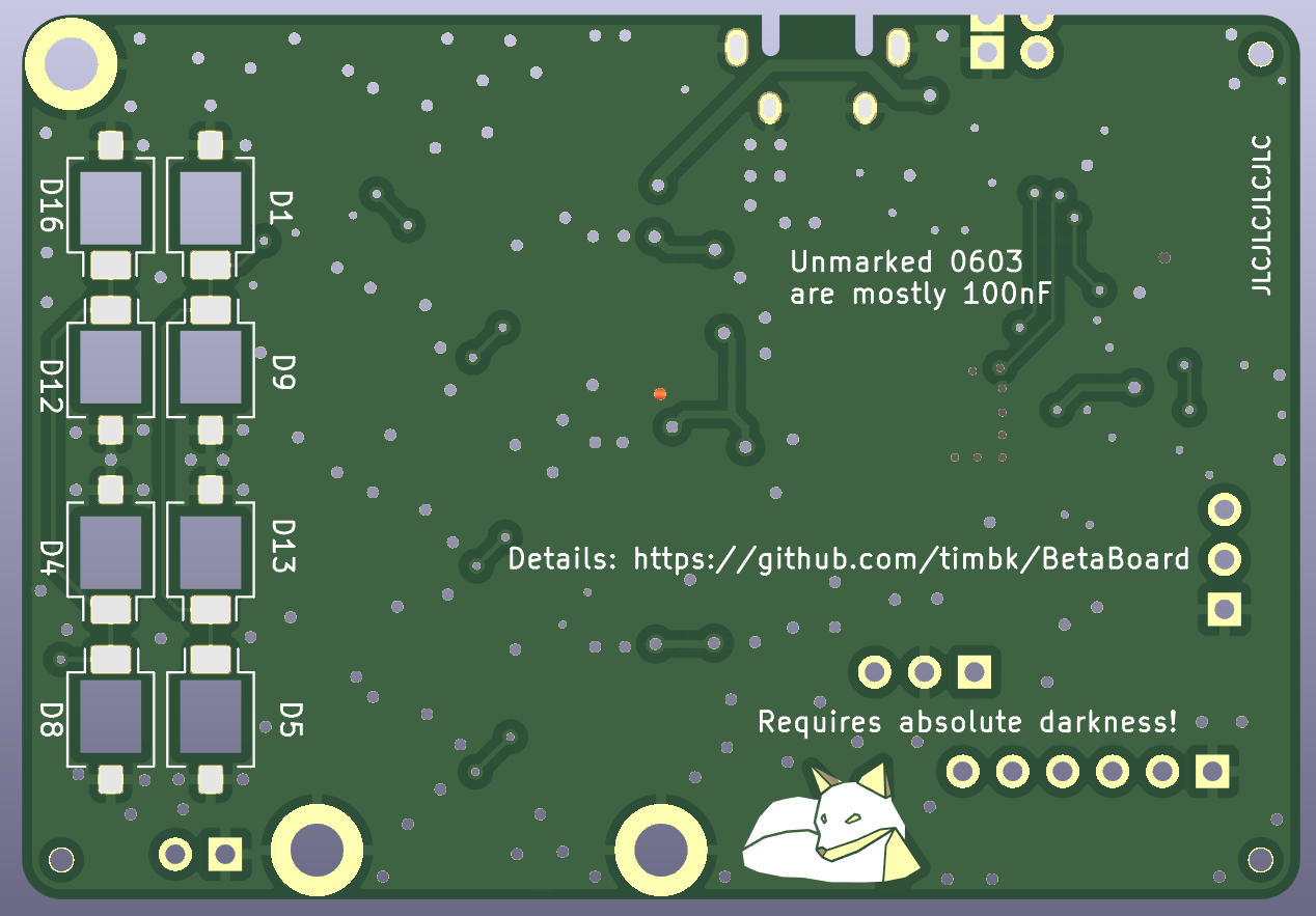
The goal was to keep it small to keep the PCB cost low and to make it fit easily. Components were chosen to keep the price low and based on availablility at the chosen manufacturer.
| Qty | Value | Footprint | References |
|---|---|---|---|
| 18 | 100n | Capacitor_SMD:C_0603_1608Metric | C3, C4, C5, C6, C10, C11, C15, C16, C18, C22, C24, C28, C30, C34, C36, C40 +2 |
| 15 | 10k | Resistor_SMD:R_0603_1608Metric | R1, R7, R10, R17, R18, R20, R25, R26, R28, R33, R34, R36, R41, R42, R44 |
| 8 | 10p | Capacitor_SMD:C_0603_1608Metric | C19, C20, C25, C26, C31, C32, C37, C38 |
| 8 | BPW34-SMD | betaBoard:Osram_BPW34S-SMD_hole | D2, D3, D6, D7, D10, D11, D14, D15 |
| 8 | DNP | OptoDevice:Osram_BPW34S-SMD | D1, D4, D5, D8, D9, D12, D13, D16 |
| 6 | 1k | Resistor_SMD:R_0603_1608Metric | R2, R3, R4, R5, R6, R11 |
| 4 | 15k | Resistor_SMD:R_0603_1608Metric | R14, R22, R30, R38 |
| 4 | 1M | Resistor_SMD:R_0603_1608Metric | R19, R27, R35, R43 |
| 4 | 470n | Capacitor_SMD:C_0603_1608Metric | C21, C27, C33, C39 |
| 4 | 47M | Resistor_SMD:R_0603_1608Metric | R15, R23, R31, R39 |
| 4 | 47p | Capacitor_SMD:C_0603_1608Metric | C23, C29, C35, C41 |
| 4 | 4K7 | Resistor_SMD:R_0603_1608Metric | R16, R24, R32, R40 |
| 4 | 4k7 | Resistor_SMD:R_0603_1608Metric | R13, R21, R29, R37 |
| 4 | LM358 | Package_SO:SOIC-8_3.9x4.9mm_P1.27mm | U4, U5, U6, U7 |
| 4 | ZMM3V3-M | Diode_SMD:D_MiniMELF | D20, D21, D22, D23 |
| 3 | 1u | Capacitor_SMD:C_0603_1608Metric | C9, C14, C17 |
| 3 | JLC Tooling Hole | betaBoard:JLC_tooling_hole | H4, H5, H6 |
| 3 | M3 Hole | MountingHole:MountingHole_2.7mm_M2.5_DIN965_Pad | H1, H2, H3 |
| 2 | 10u | Capacitor_SMD:C_1206_3216Metric | C1, C2 |
| 2 | 1N5819WS | Diode_SMD:D_SOD-323 | D17, D18 |
| 2 | 27.4 | Resistor_SMD:R_0603_1608Metric | R8, R9 |
| 2 | 30p | Capacitor_SMD:C_0603_1608Metric | C12, C13 |
| 2 | C26638 | betaBoard:TS-1187A-B-A-B | SW1, SW2 |
| 2 | DNP | Connector_PinHeader_2.54mm:PinHeader_1x03_P2.54mm_Vertical | J4, J5 |
| 1 | 100 | Resistor_SMD:R_0603_1608Metric | R12 |
| 1 | AMPHENOL_10103592-0001LF | betaBoard:AMPHENOL_10103592-0001LF | J2 |
| 1 | AMS1117-3.3_SOT223 | Package_TO_SOT_SMD:SOT-223-3_TabPin2 | U1 |
| 1 | DNP | betaBoard:PinHeader_1x02_P2.54mm_castellation | J1 |
| 1 | DNP | Jumper:SolderJumper-2_P1.3mm_Bridged2Bar_Pad1.0x1.5mm | JP1 |
| 1 | DNP | Connector_PinSocket_2.54mm:PinSocket_1x02_P2.54mm_Vertical | J3 |
| 1 | DNP | Connector_PinHeader_2.54mm:PinHeader_1x06_P2.54mm_Vertical | J6 |
| 1 | LED | LED_SMD:LED_0603_1608Metric | D19 |
| 1 | LOGO | AAA_stickaas:polyfox | G*** |
| 1 | RP2040 | Package_DFN_QFN:QFN-56-1EP_7x7mm_P0.4mm_EP3.2x3.2mm | U3 |
| 1 | W25Q128JVSIQ | Package_SO:SOIC-8_5.23x5.23mm_P1.27mm | U2 |
| 1 | X322512MSB4SI | Crystal:Crystal_SMD_3225-4Pin_3.2x2.5mm | Y1 |

chatelao/xDuinoRail-Decoder
The friendly decoder development plattform for model railroad tinkers.

vvuk/babelfish
Babelfish is a hardware device and associated software to allow using a USB keyboard and mouse on a variety of retro computers.


3komma3volt/LoRaWeatherStation_Hardware
A simple stand-alone self-sufficient weather station using LoRa for data transmission


lhr-solar/Power-Generation-Sunscatter
The current maintainer of this project is Matthew Yu as of 07/16/2023. His email is matthewjkyu@gmail.com.

MasaoC/GPS-TFT-Map_PONS
鳥人間コンテストに特化したGNSS誘導システム。人力飛行機のパイロットが使いやすいことを目標にした航法装置です。ハードとソフトをオープンソースで開発しています。

gab-k/RP2040-Decoder
Cost effective DIY DCC Decoder for model railroad locomotives
It measures 65 × 45 mm and has 2 copper layers, 1.6 mm thick.
132 parts, built around the RP2040, LM358, W25Q128JVSIQ and ZMM3V3-M. The full list of its parts is on this page, with links to each part's symbol and footprint where PCBKit's library has them.
From the timbk/BetaBoard repository on GitHub, at the commit this page was made from: the board is hardware/betaBoard_r1.0/betaBoard.kicad_pcb and its schematic hardware/betaBoard_r1.0/betaBoard.kicad_sch. PCBKit opens the board in the browser, with nothing to install.
Its repository publishes it under the BSD-2-Clause licence: you may reuse it on that licence's terms (keep the author's notice, and for a copyleft licence share your changes alike).