2 layers25 × 20 mm
RP2040-Decoder
gab-k/RP2040-Decoder
Cost effective DIY DCC Decoder for model railroad locomotives
57 parts131

 gab-k/RP2040-Decoder131
Cost effective DIY DCC Decoder for model railroad locomotives
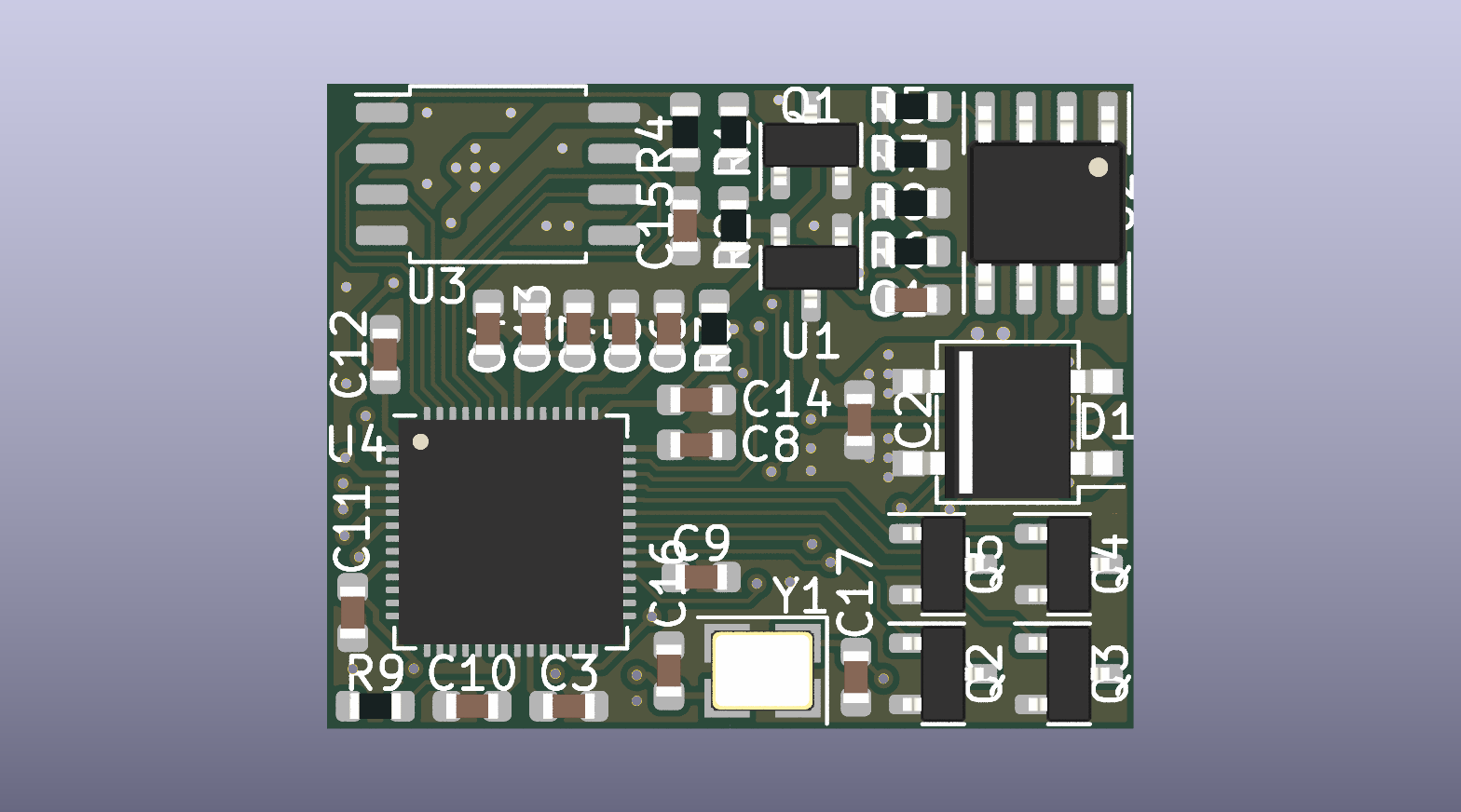
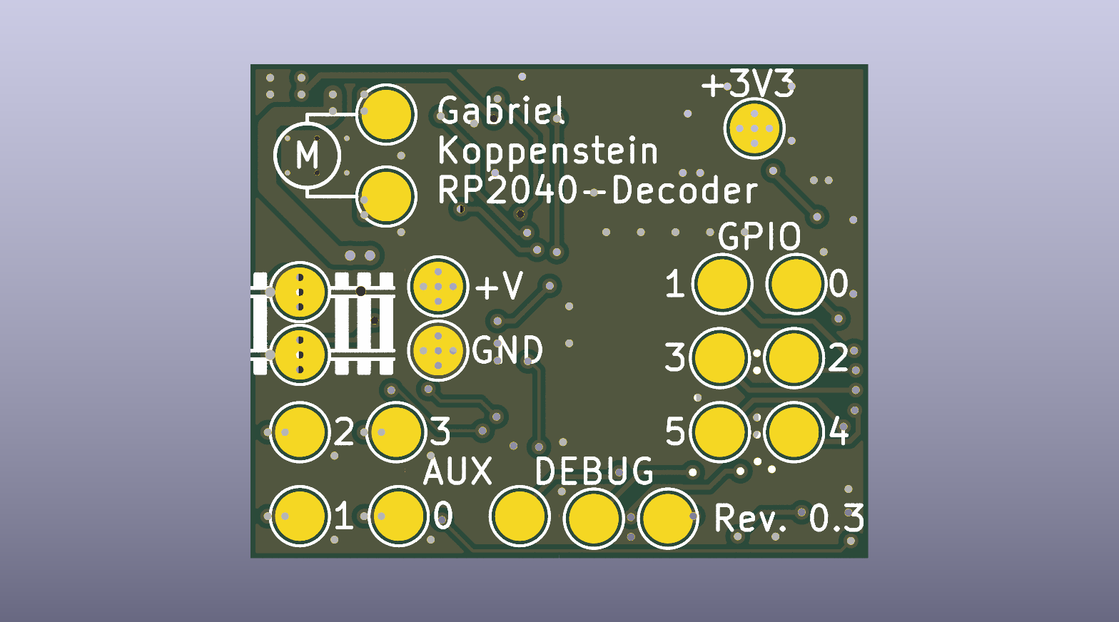
RP2040-Decoder is an open-source printed circuit board by gab-k, from the gab-k/RP2040-Decoder repository on GitHub. It is a 4-layer board of 25 × 20 mm with 68 parts on 68 nets, routed with 426 tracks and 114 vias.
It is built around the RP2040, BDR6133 and W25Q64JVSSIQ, with the MIC5200-3.3YS, SI1308EDL and 1N5819WS among its other parts. Its parts include 21 connectors, 18 capacitors, 15 resistors, 5 transistors and 4 ICs. It belongs with the RP2040 boards of this library.


Designed to be a low-cost, open-source alternative to commercial DCC decoders, it utilizes the Raspberry Pi RP2040 dual-core microcontroller. The decoder features DCC protocol decoding and command interpretation alongside motor control in a compact 25x20 mm form factor.
The system uses each of the two ARM Cortex-M0+ cores for separate tasks:
Optimized for ease of use; supports UF2 drag-and-drop flashing and serial logging.
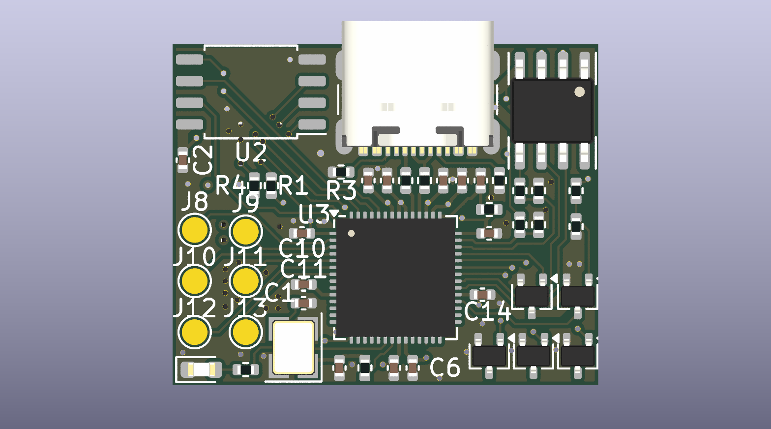
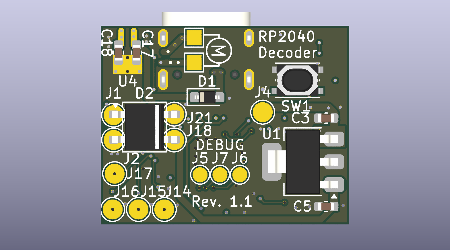
Revision without USB, one sided assembly, flashed via SWD.
To get started, you will first need the hardware. The different options for acquiring a board are outlined here.
For the software, you have a few options: you can either build it from source or use the ready-to-flash binaries built by the CI pipeline on each release. Flashing the firmware can be done via SWD or, if you are using the USB hardware version, simply by dragging and dropping the file using your regular file explorer.
| Qty | Value | Footprint | References |
|---|---|---|---|
| 9 | 100n | Capacitor_SMD:C_0402_1005Metric | C2, C6, C7, C10, C11, C12, C14, C15, C16 |
| 9 | Conn_01x01 | TestPoint:TestPoint_Pad_D1.5mm | J5, J6, J7, J8, J9, J10, J11, J12, J13 |
| 9 | Conn_01x01 | TestPoint:TestPoint_Pad_D2.0mm | J1, J2, J4, J14, J15, J16, J17, J18, J21 |
| 5 | 1k | Resistor_SMD:R_0402_1005Metric | R4, R5, R10, R13, R15 |
| 5 | Si1308EDL | Package_TO_SOT_SMD:SOT-323_SC-70 | Q1, Q2, Q3, Q4, Q5 |
| 4 | 10u | Capacitor_SMD:C_0603_1608Metric | C3, C5, C17, C18 |
| 4 | 6k8 | Resistor_SMD:R_0402_1005Metric | R8, R9, R12, R14 |
| 3 | 10u | Capacitor_SMD:C_0402_1005Metric | C8, C9, C13 |
| 2 | 10p | Capacitor_SMD:C_0402_1005Metric | C1, C4 |
| 2 | 27 | Resistor_SMD:R_0402_1005Metric | R6, R7 |
| 2 | 5k1 | Resistor_SMD:R_0402_1005Metric | R2, R3 |
| 2 | Conn_01x01 | TestPoint:TestPoint_Pad_1.5x1.5mm | J19, J20 |
| 1 | 1N5819WS | Diode_SMD:D_SOD-323_HandSoldering | D1 |
| 1 | 200 | Resistor_SMD:R_0402_1005Metric | R11 |
| 1 | BDR6133 | RP2040-Decoder_Additional_Footprints:SOIC-8-1EP_3.9x4.9mm_P1.27mm_EP2.41x3.3mm_ThermalVias | U4 |
| 1 | DNF | Resistor_SMD:R_0402_1005Metric | R1 |
| 1 | KMB24F | Package_TO_SOT_SMD:TO-269AA | D2 |
| 1 | LED | LED_SMD:LED_0603_1608Metric | D3 |
| 1 | MIC5200-3.3YS | Package_TO_SOT_SMD:SOT-223 | U1 |
| 1 | RP2040 | Package_DFN_QFN:QFN-56-1EP_7x7mm_P0.4mm_EP3.2x3.2mm | U3 |
| 1 | USB_C_Receptacle_USB2.0_16P | Connector_USB:USB_C_Receptacle_GCT_USB4105-xx-A_16P_TopMnt_Horizontal | J3 |
| 1 | W25Q64JVSSIQ | RP2040-Decoder_Additional_Footprints:SOIC-8_5.23x5.23mm_P1.27mm | U2 |
| 1 | X322512MSB4SI | Crystal:Crystal_SMD_3225-4Pin_3.2x2.5mm | Y1 |
| 1 | YTS1T0162AWJ00 | RP2040-Decoder_Additional_Footprints:SW_Push_1P1T_NO_Vertical_Wuerth_434133025816 | SW1 |
gab-k/RP2040-Decoder
Cost effective DIY DCC Decoder for model railroad locomotives

chatelao/xDuinoRail-Decoder
The friendly decoder development plattform for model railroad tinkers.

xDuinoRails/xDuinoRails_Thor
Make a Seeed XIAO board a mtc21 decoder, all the electronics needed is on this little board: - mtc21/plux16 compatible connector - DC Motor - 2x Functions - DCC / DCC-ACK / RailCom

ABaboshin/IoTrains
The existing systems in the market are either with old roots (DCC) or not opensource (Märklin). More then that they were built over 20 years ago and therefore have historical restrictions.


adammakesthingsdev/Orpheus-Pico-Kicad
Kicad files and JLCPCB production gerbers for Orpheus Pico

Enderman8843/illuminati
illuminati is a precession drafting triangle with many inbuilt microprocessor and wifi

Enderman8843/Rhenium
Rhenium is a Keyboard that is powered by RP2040 microprocessor that uses a USB-C,
It measures 25 × 20 mm and has 4 copper layers, 1.61 mm thick.
68 parts, built around the RP2040, BDR6133, W25Q64JVSSIQ and MIC5200-3.3YS. The full list of its parts is on this page, with links to each part's symbol and footprint where PCBKit's library has them.
From the gab-k/RP2040-Decoder repository on GitHub, at the commit this page was made from: the board is KiCad/USB/RP2040-Decoder.kicad_pcb and its schematic KiCad/Legacy/RP2040-Decoder.kicad_sch. PCBKit opens the board in the browser, with nothing to install.
Its repository states no licence, so its author keeps all rights: ask gab-k before reusing the design.