2 layers170.2 × 137.2 mm
MCS19
ZeniteSolar/MCS19
Módulo de Carregamento do Sistema da embarcação solar Guarapuvu II (Zênite Solar)
160 parts1GPL-3.0
 ZeniteSolar/MCS191
Módulo de Carregamento do Sistema da embarcação solar Guarapuvu II (Zênite Solar)
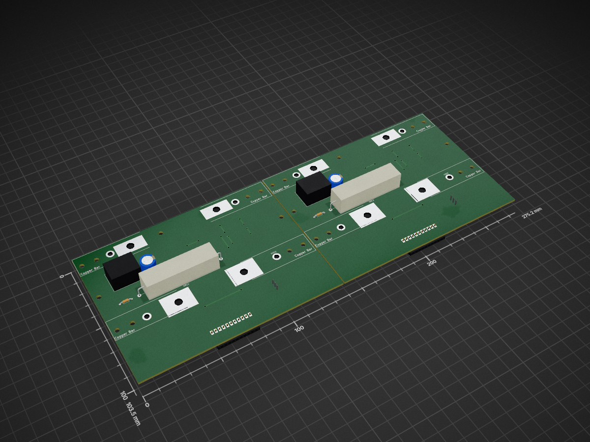
Main panel charger is an open-source printed circuit board by ZeniteSolar, from the ZeniteSolar/MCS19 repository on GitHub, published under the GPL-3.0 licence. It is a 2-layer board of 275.2 × 103.5 mm with 222 parts on 49 nets, routed with 1,010 tracks and 36 vias.
It is built around the LM324, LM7812 and LL4148, with the BCV27 among its other parts. Its parts include 68 resistors, 40 capacitors, 20 diodes, 6 ICs and 6 transistors. It belongs with the power and interfaces and adapters boards and the AVR (ATmega, ATtiny) boards of this library.


Módulo de Carregamento do Sistema 2019
Embarcação Guarapuvu II
Equipe Zênite Solar
Este módulo é responsável por gerenciar o carregamento do sistema com a finalidade de garantir segurança para a embarcação.
| Qty | Value | Footprint | References |
|---|---|---|---|
| 30 | 100n | Capacitor_SMD:C_0805_2012Metric_Pad1.15x1.40mm_HandSolder | C301, C301, C302, C302, C303, C303, C304, C304, C305, C305, C306, C306, C307, C307, C801, C801 +14 |
| 26 | 10k | Resistor_SMD:R_0805_2012Metric_Pad1.15x1.40mm_HandSolder | R301, R301, R303, R303, R304, R304, R308, R308, R309, R309, R310, R310, R312, R312, R313, R313 +10 |
| 24 | MountingHole | MountingHole:MountingHole_3.2mm_M3 | H1, H1, H2, H2, H3, H3, H4, H4, H301, H301, H302, H302, H303, H303, H304, H304 +8 |
| 12 | 1k | Resistor_SMD:R_0805_2012Metric_Pad1.15x1.40mm_HandSolder | R305, R305, R306, R306, R307, R307, R314, R314, R315, R315, R316, R316 |
| 8 | LL4148 | Diode_SMD:D_MiniMELF_Handsoldering | D1, D1, D802, D802, D803, D803, D804, D804 |
| 6 | 120 | Resistor_SMD:R_0805_2012Metric_Pad1.15x1.40mm_HandSolder | R805, R805, R806, R806, R809, R809 |
| 6 | 1k2 | Resistor_SMD:R_0805_2012Metric_Pad1.15x1.40mm_HandSolder | R801, R801, R802, R802, R811, R811 |
| 6 | Jp_TEST | Resistor_SMD:R_0805_2012Metric_Pad1.15x1.40mm_HandSolder | JP801, JP801, JP802, JP802, JP803, JP803 |
| 4 | 100k | Resistor_SMD:R_0805_2012Metric_Pad1.15x1.40mm_HandSolder | R302, R302, R311, R311 |
| 4 | 100nF | Capacitor_SMD:C_0805_2012Metric_Pad1.15x1.40mm_HandSolder | C2, C2, C3, C3 |
| 4 | 1R | Resistor_SMD:R_0805_2012Metric_Pad1.15x1.40mm_HandSolder | R807, R807, R808, R808 |
| 4 | 2k5 | Resistor_SMD:R_0805_2012Metric_Pad1.15x1.40mm_HandSolder | R813, R813, R814, R814 |
| 4 | 470 | Resistor_SMD:R_0805_2012Metric_Pad1.15x1.40mm_HandSolder | R815, R815, R816, R816 |
| 4 | 4V7 | Diode_SMD:D_MiniMELF_Handsoldering | D301, D301, D302, D302 |
| 4 | BCV27 | Package_TO_SOT_SMD:TSOT-23_HandSoldering | Q801, Q801, Q803, Q803 |
| 4 | GRN_LED | LED_SMD:LED_0805_2012Metric_Pad1.15x1.40mm_HandSolder | D806, D806, D808, D808 |
| 2 | +BAT | MountingHole:MountingHole_3.2mm_M3_DIN965_Pad | H802, H802 |
| 2 | 10R | Resistor_THT:R_Axial_Power_L48.0mm_W12.5mm_P55.88mm | R812, R812 |
| 2 | 1uF | Capacitor_Tantalum_SMD:CP_EIA-6032-20_AVX-F_Pad2.25x2.35mm_HandSolder | C4, C4 |
| 2 | 1uF | Capacitor_SMD:C_0805_2012Metric_Pad1.15x1.40mm_HandSolder | C1, C1 |
| 2 | 4700u | Capacitor_THT:CP_Radial_D10.0mm_P5.00mm | C812, C812 |
| 2 | 500mA | Fuse:Fuse_1206_3216Metric_Pad1.42x1.75mm_HandSolder | F1, F1 |
| 2 | 60R | Resistor_THT:R_Axial_DIN0204_L3.6mm_D1.6mm_P7.62mm_Horizontal | TH801, TH801 |
| 2 | B_CH | TestPoint:TestPoint_Pad_D1.5mm | TP803, TP803 |
| 2 | B_OFF | TestPoint:TestPoint_Pad_D1.5mm | TP809, TP809 |
| 2 | B_ON | TestPoint:TestPoint_Pad_D1.5mm | TP804, TP804 |
| 2 | CH+ | TestPoint:TestPoint_Pad_D1.5mm | TP808, TP808 |
| 2 | CH- | TestPoint:TestPoint_Pad_D1.5mm | TP806, TP806 |
| 2 | Charge | TestPoint:TestPoint_Pad_D1.5mm | TP802, TP802 |
| 2 | Conn_01x11 | Connector_PinSocket_2.54mm:PinSocket_1x11_P2.54mm_Horizontal | J1, J1 |
| 2 | F_BAT- | MountingHole:MountingHole_3.2mm_M3_DIN965_Pad | H804, H804 |
| 2 | Fuse Mega 200A | KicadZeniteSolarLibrary18:MegaFuse | F802, F802 |
| 2 | K100A | Connector_PinHeader_2.54mm:PinHeader_1x03_P2.54mm_Vertical_SMD_Pin1Right | K1, K1 |
| 2 | K100B | KicadZeniteSolarLibrary18:Mega_Relay_K100_separated | U2, U2 |
| 2 | LM324 | Package_SO:SOIC-14_3.9x8.7mm_P1.27mm | U301, U301 |
| 2 | LM7812 | KicadZeniteSolarLibrary18:TO-220-3_Horizontal_TabDown_SMD | U1, U1 |
| 2 | Logo_Open_Hardware_Small | Symbol:OSHW-Logo2_9.8x8mm_Copper | LOGO2, LOGO2 |
| 2 | Logo_Open_Hardware_Small | KicadZeniteSolarLibrary18:zenite | LOGO1, LOGO1 |
| 2 | Logo_Open_Hardware_Small | Symbol:KiCad-Logo2_5mm_Copper | LOGO3, LOGO3 |
| 2 | Net-Tie_2 | Resistor_SMD:R_0805_2012Metric_Pad1.15x1.40mm_HandSolder | NT801, NT801 |
| 2 | OFF | TestPoint:TestPoint_Pad_D1.5mm | TP807, TP807 |
| 2 | ON | TestPoint:TestPoint_Pad_D1.5mm | TP805, TP805 |
| 2 | Q_NPN_BEC | Package_TO_SOT_SMD:TSOT-23_HandSoldering | Q802, Q802 |
| 2 | RED_LED | LED_SMD:LED_0805_2012Metric_Pad1.15x1.40mm_HandSolder | D805, D805 |
| 2 | RL_OFF | TestPoint:TestPoint_Pad_D1.5mm | TP812, TP812 |
| 2 | RL_ON | TestPoint:TestPoint_Pad_D1.5mm | TP801, TP801 |
| 2 | SANYOU_SRD_Form_C | Relay_THT:Relay_SPDT_SANYOU_SRD_Series_Form_C | K802, K802 |
| 2 | TH+ | TestPoint:TestPoint_Pad_D1.5mm | TP810, TP810 |
| 2 | TH- | TestPoint:TestPoint_Pad_D1.5mm | TP811, TP811 |
| 2 | U_BAT+ | MountingHole:MountingHole_3.2mm_M3_DIN965_Pad | H801, H801 |
| 2 | U_BAT- | MountingHole:MountingHole_3.2mm_M3_DIN965_Pad | H803, H803 |
| 2 | YLW_LED | LED_SMD:LED_0805_2012Metric_Pad1.15x1.40mm_HandSolder | D807, D807 |
ZeniteSolar/MCS19
Módulo de Carregamento do Sistema da embarcação solar Guarapuvu II (Zênite Solar)

ZeniteSolar/MIC19
Módulo de Interface do Controle da embarcação solar Guarapuvu II (Zênite Solar)


SunnyYoshimitsu/Reconfigurable-Space-Compute-Cluster
Here will be the repository for an "extremely reconfigurable satellite" aimed toward at competing in NASA Minds and hopefully assist Artemis in its missions.

ZeniteSolar/MAM21
Dados os requisitos e especificações apresentadas anteriormente, foi definido que a topologia utilizada será um conversor chopper, por não haver necessidade de elevação de tensão e por este permitir a variação da tensão…


ZeniteSolar/MSC22
Atalização do Módulo Sensor Can 19 https://github.com/ZeniteSolar/MSC19 Agora com alimentação bipolar +/- 15V para os sensores. Estágio analógico devidamente ajustado.
It measures 275.2 × 103.5 mm and has 2 copper layers, 1.6 mm thick.
222 parts, built around the LM324, LM7812, LL4148 and BCV27. The full list of its parts is on this page, with links to each part's symbol and footprint where PCBKit's library has them.
From the ZeniteSolar/MCS19 repository on GitHub, at the commit this page was made from: the board is hardware/export_files/main_panel_charger.kicad_pcb. PCBKit opens the board in the browser, with nothing to install.
Its repository publishes it under the GPL-3.0 licence: you may reuse it on that licence's terms (keep the author's notice, and for a copyleft licence share your changes alike).