2 layers172.9 × 81.5 mm

 ZeniteSolar/MCB192
Modulo de carregamento das baterias auxiliares
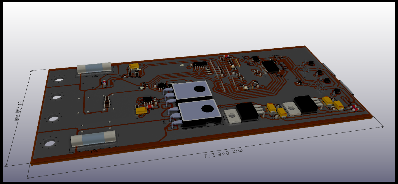
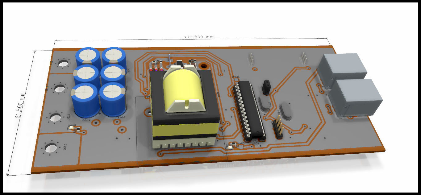
MCB19 panel is an open-source printed circuit board by ZeniteSolar, from the ZeniteSolar/MCB19 repository on GitHub, published under the GPL-3.0 licence. It is a 2-layer board of 256.5 × 172.9 mm with 411 parts on 68 nets, routed with 3,924 tracks and 1,132 vias.
It is built around the ATMEGA328P-PU, MCP2551-I/SN and INA240A4D, with the LM324, LM7805 and LM7812 among its other parts. Its parts include 150 capacitors, 93 resistors, 42 diodes, 24 ICs and 24 connectors. It belongs with the power and interfaces and adapters boards and the AVR (ATmega, ATtiny) boards of this library.


Módulo Carregamento das Baterias 2019
Embarcação Guarapuvu II
Equipe Zênite Solar
Este módulo é responsável por carregar e gerenciar a carga da bateria auxiliar (rádio e bombas de porão) e da bateria extra (direção elétrica) a partir da energia da bateria principal.
Carregar a bateria
Carregar por CC e CV
Proteções
Monitoramento do estado das baterias
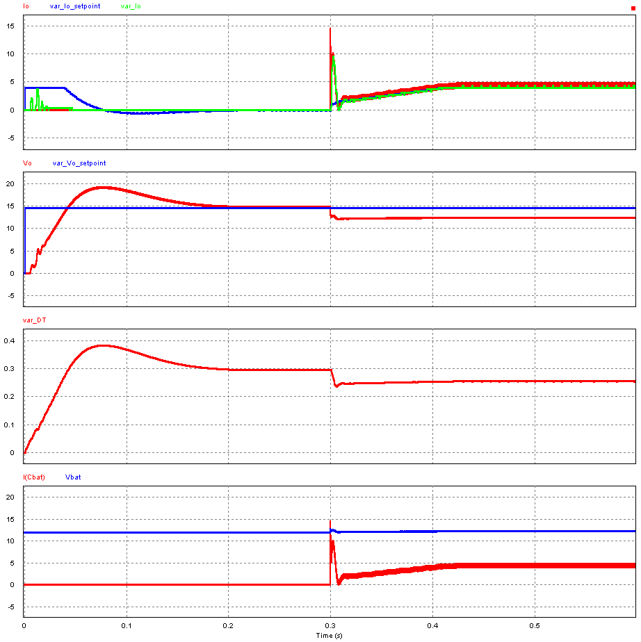
Como no sistema, a tensão da bateria principal (entrada) será sempre maior que a tensão a tenão da bateria extra/auxiliar (saída), foi escolhido projetar um conversor estatico CC-CC Buck, com chaveamento síncrono (dois mosfets) para maior obter eficiencia.
 | 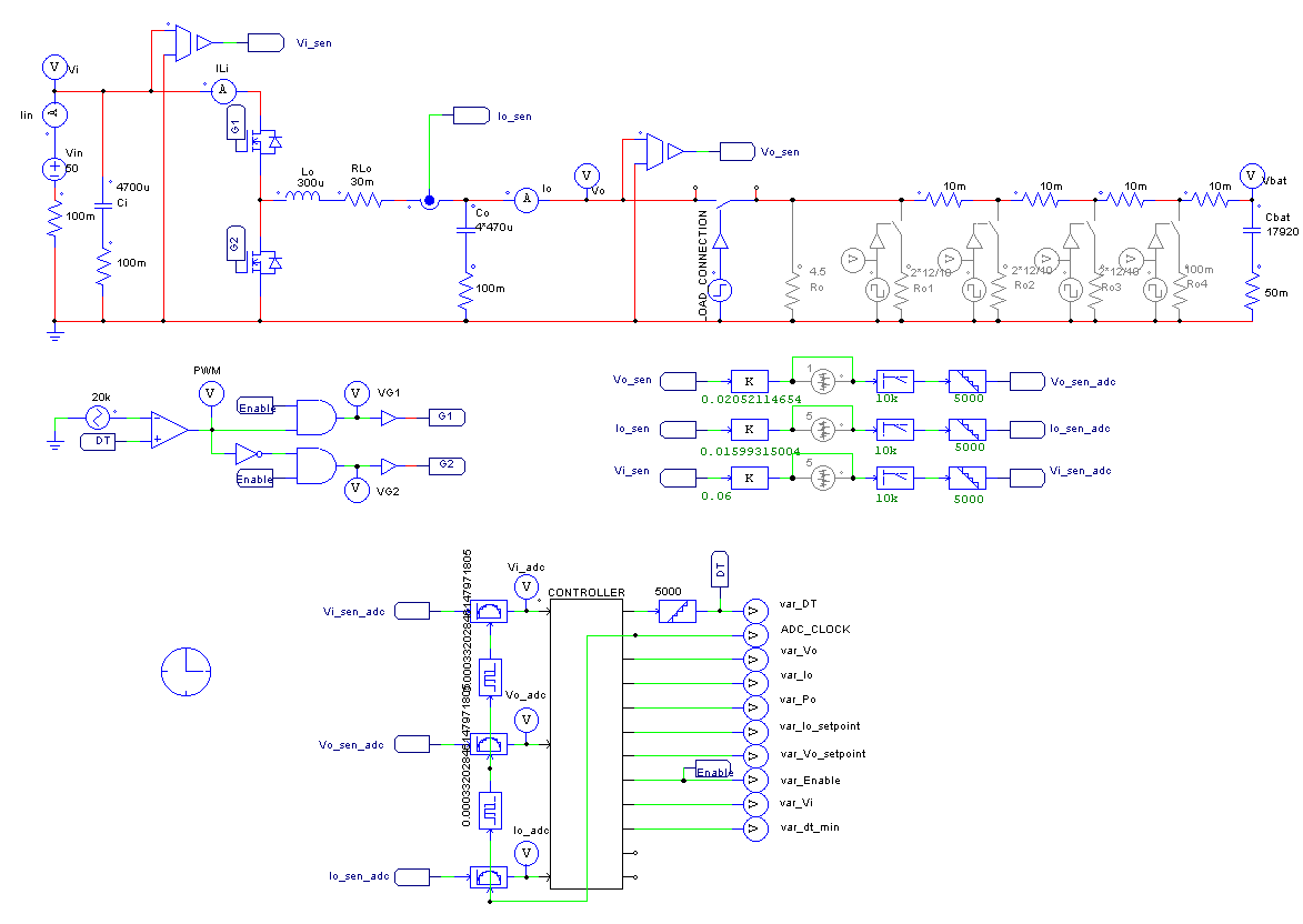 |
|---|
Configurações gerais do sistema
//#Definições do conversor
#define VO_SETPOINT 	13.2
#define IO_MAX      	8
#define VI_MIN 21No arquivo adc.c são lidos os valores dos ADCs e convertidos a valores "humanos", tambem é chamada a função de controle
    static const float vi_coeff = 0.06582490575070313f;
    static const float vo_coeff = 0.06717781789490249f;
static const float io_coeff = 0.01599315004f; No arquivo control.c é executado o algoritmo de controle (PiVo em cascata com PiIo), para sintonizar o controlador tem que mudar as constantes Kp e Ti
/*          PI CONTROL ALGORITHM - SERIES IMPLEMENTATION
** /desc    Algoritimo para Controlador Proporcional Integrativo Diferencial.
**  ref1:
https://e2e.ti.com/cfs-file/__key/communityserver-discussions-components-files/902/PI-controller-equations.pdf

** /var r é o valor desejado para a saída, o 'set-point'.
** /var y é o valor da saída.
** /ret     retorna a ação de controle u.
*/
inline float piVo(float r, float y){
    // PI CONFIGURATIONS:
    const float Kp = 0.5;           // analog series proportional gain
    const float Ti = 0.1;          // analog series integration period
    const float Ts = PERIOD;        // digital sampling period

    // INTERNAL CONSTANTS COMPUTATION:
    const float a0 = -Kp;           // IIR coefficient for old sample
    const float a1 = Kp*(1+Ts/Ti);  // IIR coefficient for new sample

    // CONTROLLER STATIC VARIABLES
    static float e0 = 0;            // old error
    static float e1 = 0;            // new error
    static float u = 0;             // control action
No arquivo machine.c é executada a maquina de estados
inline void machine_run(void)
{
    if(print_adc){ print_infos(); print_adc = 0;}

    if(machine_clk){
        machine_clk = 0;

        if(error_flags.all){
            print_system_flags();
            print_error_flags();
            print_infos();
            set_state_error();
        }

        switch(state_machine){
            case STATE_INITIALIZING:
                task_initializing();

                break;
            case STATE_IDLE:
                task_idle();

                break;
case STATE_RUNNING: | Qty | Value | Footprint | References |
|---|---|---|---|
| 54 | 100nF | Capacitor_SMD:C_0805_2012Metric_Pad1.15x1.40mm_HandSolder | C201, C201, C201, C202, C202, C202, C205, C205, C205, C302, C302, C302, C303, C303, C303, C401 +38 |
| 30 | 100n | Capacitor_SMD:C_0805_2012Metric_Pad1.15x1.40mm_HandSolder | C615, C615, C615, C616, C616, C616, C619, C619, C619, C620, C620, C620, C622, C622, C622, C623 +14 |
| 18 | 1uF | Capacitor_Tantalum_SMD:CP_EIA-6032-20_AVX-F_Pad2.25x2.35mm_HandSolder | C301, C301, C301, C304, C304, C304, C501, C501, C501, C504, C504, C504, C604, C604, C604, C628 +2 |
| 18 | LL4148 | Diode_SMD:D_MiniMELF_Handsoldering | D301, D301, D301, D401, D401, D401, D501, D501, D501, D601, D601, D601, D602, D602, D602, D603 +2 |
| 15 | 10k | Resistor_SMD:R_0805_2012Metric_Pad1.15x1.40mm_HandSolder | R203, R203, R203, R401, R401, R401, R410, R410, R410, R604, R604, R604, R605, R605, R605 |
| 12 | 12V | Diode_SMD:D_MiniMELF_Handsoldering | DZ601, DZ601, DZ601, DZ602, DZ602, DZ602, DZ603, DZ603, DZ603, DZ604, DZ604, DZ604 |
| 12 | 1k | Resistor_SMD:R_0805_2012Metric_Pad1.15x1.40mm_HandSolder | R201, R201, R201, R402, R402, R402, R403, R403, R403, R611, R611, R611 |
| 12 | 22pF | Capacitor_SMD:C_0805_2012Metric_Pad1.15x1.40mm_HandSolder | C203, C203, C203, C204, C204, C204, C403, C403, C403, C404, C404, C404 |
| 12 | 330 | Resistor_SMD:R_0805_2012Metric_Pad1.15x1.40mm_HandSolder | R404, R404, R404, R406, R406, R406, R616, R616, R616, R618, R618, R618 |
| 12 | 4.7u | Capacitor_SMD:C_1206_3216Metric_Pad1.42x1.75mm_HandSolder | C613, C613, C613, C614, C614, C614, C617, C617, C617, C618, C618, C618 |
| 12 | 47uF | Capacitor_THT:CP_Radial_D12.5mm_P5.00mm | C603, C603, C603, C608, C608, C608, C609, C609, C609, C610, C610, C610 |
| 12 | LED_RED | LED_SMD:LED_0805_2012Metric_Pad1.15x1.40mm_HandSolder | D402, D402, D402, D403, D403, D403, D607, D607, D607, D608, D608, D608 |
| 9 | 680 | Resistor_SMD:R_0805_2012Metric_Pad1.15x1.40mm_HandSolder | R407, R407, R407, R408, R408, R408, R409, R409, R409 |
| 9 | ES2A | Diode_SMD:D_MiniMELF_Handsoldering | D604, D604, D604, D605, D605, D605, D606, D606, D606 |
| 6 | 10R | Resistor_SMD:R_2512_6332Metric | R607, R607, R607, R615, R615, R615 |
| 6 | 10R | Resistor_SMD:R_2512_6332Metric_Pad1.52x3.35mm_HandSolder | R608, R608, R608, R617, R617, R617 |
| 6 | 15k | Resistor_SMD:R_0805_2012Metric_Pad1.15x1.40mm_HandSolder | R609, R609, R609, R613, R613, R613 |
| 6 | 16MHz | Crystal:Crystal_HC49-U_Vertical | Y201, Y201, Y201, Y401, Y401, Y401 |
| 6 | 1k2 | Resistor_SMD:R_0805_2012Metric_Pad1.15x1.40mm_HandSolder | R610, R610, R610, R614, R614, R614 |
| 6 | 4700uF | Capacitor_THT:CP_Radial_D12.5mm_P5.00mm | C602, C602, C602, C621, C621, C621 |
| 6 | 47nF | Capacitor_SMD:C_1210_3225Metric_Pad1.42x2.65mm_HandSolder | C606, C606, C606, C607, C607, C607 |
| 6 | 4R7 | Resistor_SMD:R_0805_2012Metric_Pad1.15x1.40mm_HandSolder | R602, R602, R602, R603, R603, R603 |
| 6 | IRFP260N | Package_TO_SOT_THT:TO-247-3_Horizontal_TabUp | Q601, Q601, Q601, Q602, Q602, Q602 |
| 6 | RJ45 | KicadZeniteSolarLibrary18:RJ45_YH59_01 | J601, J601, J601, J602, J602, J602 |
| 3 | +BAT_IN | MountingHole:MountingHole_5.3mm_M5_Pad_Via | J611, J611, J611 |
| 3 | +BAT_OUT | MountingHole:MountingHole_5.3mm_M5_Pad_Via | J613, J613, J613 |
| 3 | -BAT_IN | MountingHole:MountingHole_5.3mm_M5_Pad_Via | J612, J612, J612 |
| 3 | -BAT_OUT | MountingHole:MountingHole_5.3mm_M5_Pad_Via | J614, J614, J614 |
| 3 | 1,5mR | KicadZeniteSolarLibrary18:R_2512_6432Metric_Reversed | R606, R606, R606 |
| 3 | 100 | Resistor_SMD:R_0805_2012Metric_Pad1.15x1.40mm_HandSolder | R411, R411, R411 |
| 3 | 10A | Fuse:Fuseholder_Cylinder-5x20mm_Stelvio-Kontek_PTF78_Horizontal_Open | F601, F601, F601 |
| 3 | 15A | Fuse:Fuseholder_Cylinder-5x20mm_Stelvio-Kontek_PTF78_Horizontal_Open | F602, F602, F602 |
| 3 | 300uH | KicadZeniteSolarLibrary18:Inductor_Nocoupled | L601, L601, L601 |
| 3 | 4k7 | Resistor_SMD:R_0805_2012Metric_Pad1.15x1.40mm_HandSolder | R202, R202, R202 |
| 3 | 500mA | Fuse:Fuse_1206_3216Metric_Pad1.42x1.75mm_HandSolder | F501, F501, F501 |
| 3 | 50k | Resistor_SMD:R_0805_2012Metric_Pad1.15x1.40mm_HandSolder | R601, R601, R601 |
| 3 | 90R | Resistor_SMD:R_0805_2012Metric_Pad1.15x1.40mm_HandSolder | R612, R612, R612 |
| 3 | ATMEGA328P-PU | Package_DIP:DIP-28_W7.62mm_Socket | U401, U401, U401 |
| 3 | BC847 | Package_TO_SOT_SMD:SOT-23 | Q604, Q604, Q604 |
| 3 | BC857 | Package_TO_SOT_SMD:SOT-23 | Q603, Q603, Q603 |
| 3 | CAN_H | TestPoint:TestPoint_Pad_2.0x2.0mm | TP207, TP207, TP207 |
| 3 | CAN_L | TestPoint:TestPoint_Pad_2.0x2.0mm | TP208, TP208, TP208 |
| 3 | DISABLE | Connector_PinSocket_2.54mm:PinSocket_1x02_P2.54mm_Vertical | J402, J402, J402 |
| 3 | ENABLE | TestPoint:TestPoint_Pad_2.0x2.0mm | TP402, TP402, TP402 |
| 3 | G5LE-1 | KicadZeniteSolarLibrary18:Relay_SPDT_SANYOU_SRD_Series_Form_C | K601, K601, K601 |
| 3 | INA240A4D | Package_SO:SOIC-8_3.9x4.9mm_P1.27mm | U602, U602, U602 |
| 3 | INT | TestPoint:TestPoint_Pad_2.0x2.0mm | TP209, TP209, TP209 |
| 3 | LM324 | Package_SO:SOIC-14_3.9x8.7mm_P1.27mm | U603, U603, U603 |
| 3 | LM5104MNOPB | Package_SO:SOIC-8_3.9x4.9mm_P1.27mm | U601, U601, U601 |
| 3 | LM7805 | KicadZeniteSolarLibrary18:TO-220-3_Horizontal_TabDown_SMD | U301, U301, U301 |
| 3 | LM7812 | KicadZeniteSolarLibrary18:TO-220-3_Horizontal_TabDown_SMD | U501, U501, U501 |
| 3 | MCP2515-xSO | Package_SO:SOIC-18W_7.5x11.6mm_P1.27mm | U202, U202, U202 |
| 3 | MCP2551-I/SN | Package_SO:SOIC-8_3.9x4.9mm_P1.27mm | U201, U201, U201 |
| 3 | PWM | TestPoint:TestPoint_Pad_2.0x2.0mm | TP401, TP401, TP401 |
| 3 | RXCAN | TestPoint:TestPoint_Pad_2.0x2.0mm | TP204, TP204, TP204 |
| 3 | SC | TestPoint:TestPoint_Pad_2.0x2.0mm | TP205, TP205, TP205 |
| 3 | SCK | TestPoint:TestPoint_Pad_2.0x2.0mm | TP206, TP206, TP206 |
| 3 | SI | TestPoint:TestPoint_Pad_2.0x2.0mm | TP201, TP201, TP201 |
| 3 | SO | TestPoint:TestPoint_Pad_2.0x2.0mm | TP202, TP202, TP202 |
| 3 | TXCAN | TestPoint:TestPoint_Pad_2.0x2.0mm | TP203, TP203, TP203 |
| 3 | USART | Connector_PinHeader_2.54mm:PinHeader_1x04_P2.54mm_Vertical | J401, J401, J401 |
| 3 | pesd1can | Package_TO_SOT_SMD:SOT-23_Handsoldering | D201, D201, D201 |

ZeniteSolar/MCS19
Módulo de Carregamento do Sistema da embarcação solar Guarapuvu II (Zênite Solar)


ZeniteSolar/MSC25
Este projeto consiste em uma placa de circuito impresso (PCB) com firmware embarcado, projetada para realizar a leitura de alta precisão de um sensor de corrente de efeito Hall e transmitir os dados através do…


ZeniteSolar/MIC19
Módulo de Interface do Controle da embarcação solar Guarapuvu II (Zênite Solar)
It measures 256.5 × 172.9 mm and has 2 copper layers, 1.6 mm thick.
411 parts, built around the ATMEGA328P-PU, MCP2551-I/SN, INA240A4D and LM324. The full list of its parts is on this page, with links to each part's symbol and footprint where PCBKit's library has them.
From the ZeniteSolar/MCB19 repository on GitHub, at the commit this page was made from: the board is hardware/MCB19_panel.kicad_pcb. PCBKit opens the board in the browser, with nothing to install.
Its repository publishes it under the GPL-3.0 licence: you may reuse it on that licence's terms (keep the author's notice, and for a copyleft licence share your changes alike).