

2 layers100 × 100 mm
Hour meter board microfit can handroute
ilomon10/embedded-totalizer-hour-meter
ESP32 engine hour meter & totalizer: firmware, SensorFrame protocol, Node host tools, KiCad PCB and a Deno device simulator
152 parts

 ZachS07/Adjustable-Buck-Converter-PCB1
Adjustable buck converter PCB with an input range up to 40V and an output between 1.23V and ~32V set by an onboard potentiometer.
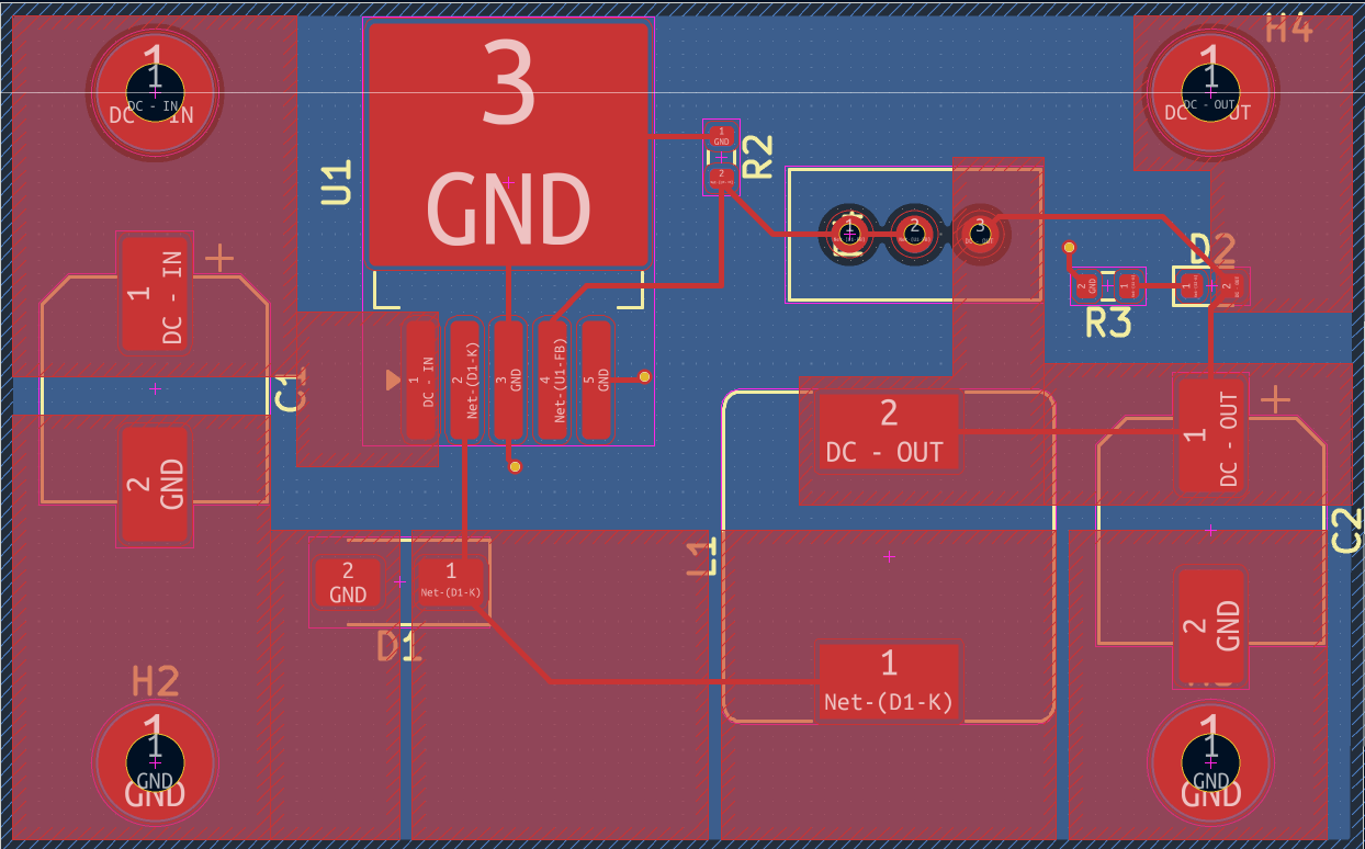
Buck Converter is an open-source printed circuit board by ZachS07, from the ZachS07/Adjustable-Buck-Converter-PCB repository on GitHub. It is a 2-layer board of 53 × 33 mm with 13 parts on 6 nets, routed with 29 tracks and 3 vias.
It is built around the LM2596S-ADJ and SS54. Its parts include 3 resistors, 2 capacitors, 2 diodes, 1 IC and 1 inductor. It belongs with the power boards of this library.
Adjustable buck converter PCB with an input range up to 40V and an output between 1.23V and ~32V set by an onboard potentiometer.
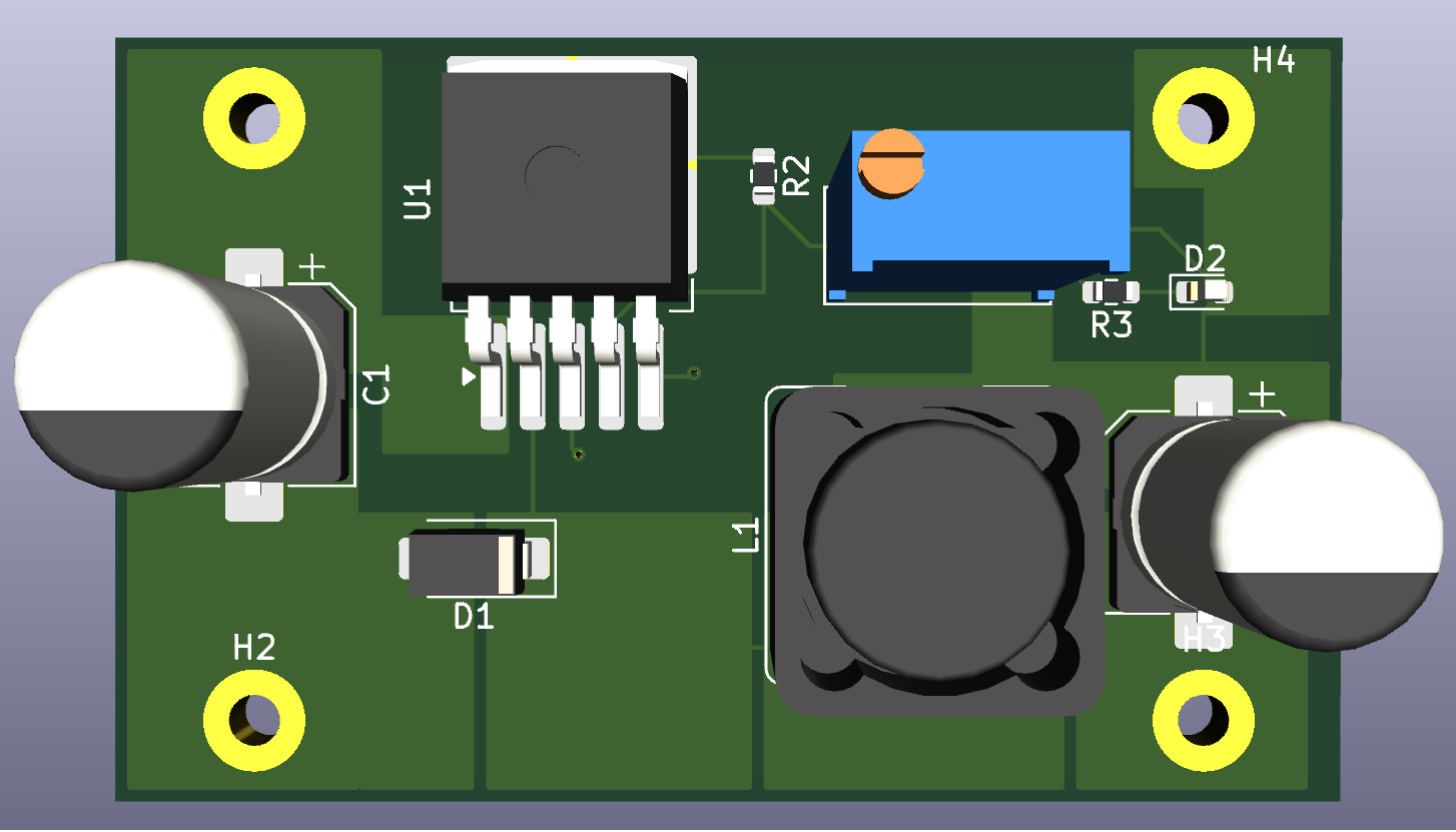
My inspiration for this came from researching the power and energy field over the summer. I wanted to put what I was learning about into practice, so I thought it'd be worthwhile to design and lay out a switching regulator board.
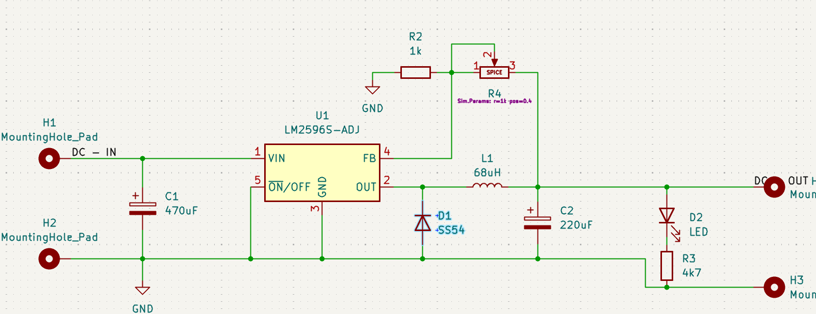
| Qty | Value | Footprint | References |
|---|---|---|---|
| 4 | MountingHole_Pad | MountingHole:MountingHole_2.2mm_M2_Pad_TopBottom | H1, H2, H3, H4 |
| 1 | 1k | Resistor_SMD:R_0603_1608Metric | R2 |
| 1 | 220uF | Capacitor_SMD:CP_Elec_8x10.5 | C2 |
| 1 | 470uF | Capacitor_SMD:CP_Elec_8x10.5 | C1 |
| 1 | 4k7 | Resistor_SMD:R_0603_1608Metric | R3 |
| 1 | 68uH | Inductor_SMD:L_Bourns_SRR1260 | L1 |
| 1 | LED | LED_SMD:LED_0603_1608Metric | D2 |
| 1 | LM2596S-ADJ | Package_TO_SOT_SMD:TO-263-5_TabPin3 | U1 |
| 1 | Potentiometer | Potentiometer_THT:Potentiometer_Bourns_3296W_Vertical | R4 |
| 1 | SS54 | Diode_SMD:D_SMA | D1 |
ilomon10/embedded-totalizer-hour-meter
ESP32 engine hour meter & totalizer: firmware, SensorFrame protocol, Node host tools, KiCad PCB and a Deno device simulator


kholia/HF-PA-v10
HF-PA-v10 ;) Is this the end of the search for a 5W Digital PA? HF-PA-v10 is now a rugged 10W PA! We also do 100W+ now ;)


Aleksei327/ESP32-C5-OBD2-Scanner
DIY dual-CAN OBD2 adapter on Seeed XIAO ESP32-C5 with a Flutter Android app. Working prototype, tested on a Citroën C3 II: full read-only ECU scan, PSA fault codes, live data. Single-sided home-etched KiCad board.
It measures 53 × 33 mm and has 2 copper layers, 1.6 mm thick.
13 parts, built around the LM2596S-ADJ and SS54. The full list of its parts is on this page, with links to each part's symbol and footprint where PCBKit's library has them.
From the ZachS07/Adjustable-Buck-Converter-PCB repository on GitHub, at the commit this page was made from: the board is Buck Converter.kicad_pcb and its schematic Buck Converter.kicad_sch. PCBKit opens the board in the browser, with nothing to install.
Its repository states no licence, so its author keeps all rights: ask ZachS07 before reusing the design.