
2 layers30 × 29.3 mm
PRJ
Juniper-Rueter/PR-J
A universal load cell amplifier for communication with klipper and an open standard for strain gauges
24 parts17

 YakshithK/Glassboard
transparent NFC business card that lights up 3 LEDs when you tap your phone — no battery, powered by your phone's RF field
Glassboard is an open-source printed circuit board by YakshithK, from the YakshithK/Glassboard repository on GitHub. It is a 2-layer board of 85.6 × 54 mm with 21 parts on 16 nets, routed with 116 tracks and 11 vias.
It is built around the ATTINY202-SSN. Its parts include 2 ICs and 1 capacitor. It belongs with the radio and wireless and power boards and the AVR (ATmega, ATtiny) boards of this library.
A transparent NFC business card that lights up when you tap your phone to it. No battery. No charging. Ever.
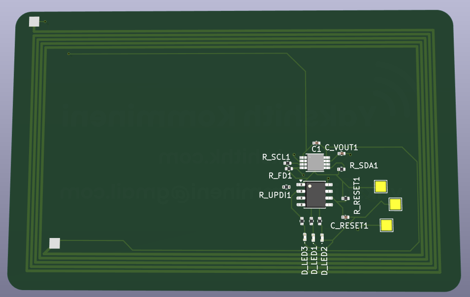

Glassboard is a credit card sized transparent circuit board. It stores my contact info and portfolio link using NFC. When someone taps their phone to it, two things happen at once: their phone opens my portfolio link, and three green LEDs on the card light up and animate.
The entire card runs off the energy from the phone's own NFC signal. There is no battery inside. Nothing to charge. The card just sits in your wallet and works whenever someone taps it.
Because it's built on a transparent substrate, you can see through the card. Every trace, every component, and the antenna spiral are all visible. It looks like a piece of glass with circuits inside.
I kept handing people plain paper business cards at hackathons. It felt wrong. I build hardware, but the card said nothing about that.
I wanted a card that proved what I do the moment someone touched it. So I built one.
The card has two chips on it.
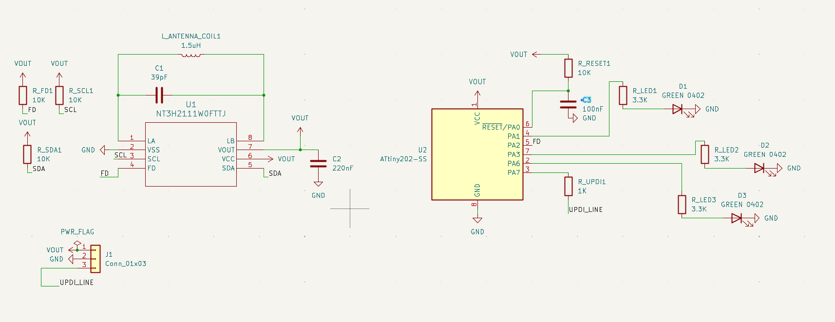
The first is the NT3H2111, an NFC chip from NXP. It stores my URL in its memory and harvests power from the phone's NFC field. When a phone gets close, the chip outputs around 3V on its power pin, which powers everything else on the card.
The second is the ATtiny202, a tiny microcontroller. It spends almost all of its time asleep, drawing basically no power. When the NFC chip detects a phone, it sends a signal to the ATtiny, which wakes up instantly, runs the LED animation for about 2 seconds, then goes back to sleep.
The antenna is a copper spiral coil built directly into the circuit board. It has 5 turns and is tuned to 13.56 MHz, which is the frequency all NFC phones use.
The three LEDs are green because green LEDs turn on at a lower voltage than blue or white ones, which matters a lot when you're running off harvested power.
Tapping it: Hold the card against the back of any NFC enabled phone (most smartphones made after 2015 have NFC). The phone will show a notification to open a link. Tap it. The LEDs on the card will also light up at the same time.
If nothing happens, try moving the card around slowly. The NFC antenna in phones is usually near the top or center of the back.
Changing the URL:
No programmer needed for this. The NFC chip handles it wirelessly.
Reprogramming the LED animation:
http://drazzy.com/package_drazzy.com_index.json)firmware/glassboard.ino and upload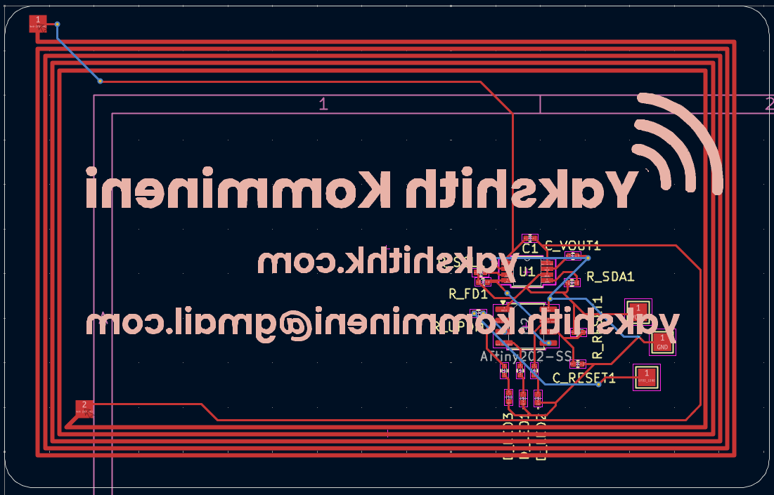
| Spec | Value |
|---|---|
| Substrate | Transparent FPC (PET) |
| Layers | 2 |
| Thickness | 0.2mm |
| Dimensions | 85.6 x 54mm (credit card size) |
| Surface finish | ENIG (gold) |
| Made by | JLCPCB |
Full BOM with purchase links is in BOM.csv.
| Part | Description | Quantity |
|---|---|---|
| NT3H2111W0FTT | NFC chip, TSSOP8 | 1 |
| ATtiny202-SSF | Microcontroller, SOIC8 | 1 |
| Wurth 150040GS73240 | Green LED, 0402 | 3 |
| 220nF cap | Decoupling, 0402 | 1 |
| 100nF cap | RESET filter, 0402 | 1 |
| 39pF cap | Antenna tuning, 0402 | 1 |
| 10pF cap | Optional tuning, 0402 (DNP) | 1 |
| 10k resistor | Pull-ups, 0402 | 4 |
| 3.3k resistor | LED current limit, 0402 | 3 |
| 1k resistor | UPDI protection, 0402 | 1 |
| Transparent FPC PCB | From JLCPCB | 1 |
Total cost is around $32 for 5 boards including shipping.
The firmware file is at firmware/glassboard.ino.
It puts the ATtiny202 into deep sleep mode. When the NT3H2111 detects a phone, its FD pin goes LOW, which triggers a hardware interrupt on the ATtiny. The MCU wakes up, runs a chase animation across the three LEDs, then goes back to sleep. The whole active cycle takes about 2 seconds.
glassboard/
├── README.md
├── BOM.csv
├── firmware/
│   └── glassboard.ino
├── hardware/
│   ├── glassboard.kicad_pro
│   ├── glassboard.kicad_sch
│   ├── glassboard.kicad_pcb
│   └── gerbers/
├── Glassboard_Zine.pdf
└── images/
    ├── 3d_front.png
    ├── 3d_back.png
    ├── pcb.png
    ├── schematic.png
    └── zine.png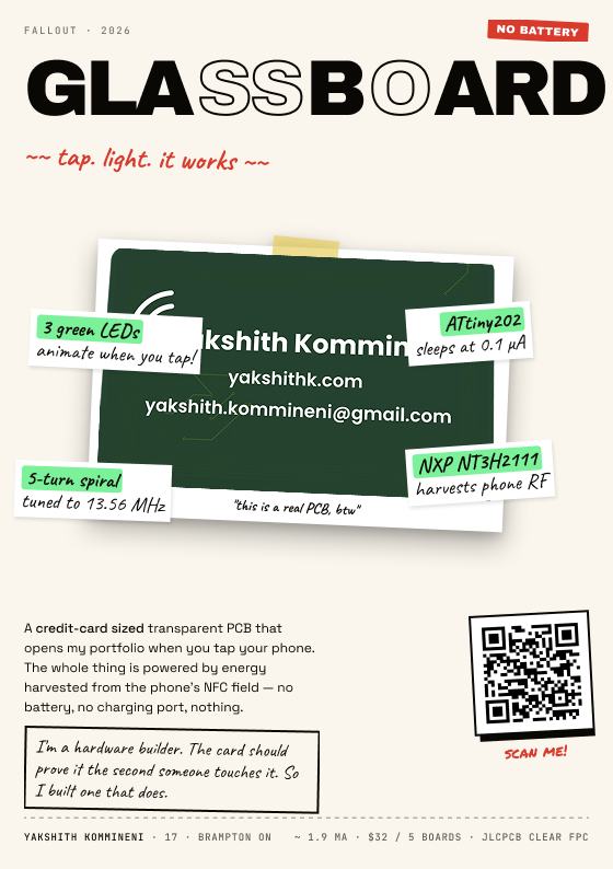
Made by Yakshith Kommineni, age 17, Brampton Ontario Canada
| Qty | Value | Footprint | References |
|---|---|---|---|
| 4 | 10K | Resistor_SMD:R_0402_1005Metric | R_FD1, R_RESET1, R_SCL1, R_SDA1 |
| 3 | 3.3K | Resistor_SMD:R_0402_1005Metric | R_LED1, R_LED2, R_LED3 |
| 3 | GREEN 0402 | LED_SMD:LED_0402_1005Metric | D_LED1, D_LED2, D_LED3 |
| 1 | 1.5uH | NFS:NFC_Credit_Card | L_ANTENNA_COIL1 |
| 1 | 100nF | Capacitor_SMD:C_0402_1005Metric | C_RESET1 |
| 1 | 1K | Resistor_SMD:R_0402_1005Metric | R_UPDI1 |
| 1 | 220nF | Capacitor_SMD:C_0402_1005Metric | C_VOUT1 |
| 1 | 39pF | Capacitor_SMD:C_0402_1005Metric | C1 |
| 1 | ATtiny202-SS | Package_SO:SOIC-8_3.9x4.9mm_P1.27mm | U2 |
| 1 | LOGO | LOGO | G*** |
| 1 | TSSOP_1W0FTTJ_NXP | NT3H2111W0FTTJ:NT3H2111W0FTTJ | U1 |
The 18 most common of 21 parts.
Juniper-Rueter/PR-J
A universal load cell amplifier for communication with klipper and an open standard for strain gauges

Dlloydev/Updi-Key
This DIY open source hardware connects inline with any UPDI programmer to provide a HV UPDI programming solution for tinyAVR® 0/1/2 series MCUs.

IamPhytan/christmas-tree-pcb
Christmas Tree PCB, made with FOSS


akita11/SolenoidStrokeUNIT
Grove端子にUART通信元(M5Stack等のマイコンやUSBシリアル変換器)を接続し、本UNITに対してコマンド送信や結果の受信を行います。Grove端子の信号は、"RXD(受信) / TXD(送信) / VDD(+5V) /…

AnOrdinaryUsername/attiny202-dev-board
A small development board for the ATtiny202 microcontroller and my first PCB!
It measures 85.6 × 54 mm and has 2 copper layers, 1.93 mm thick.
21 parts, built around the ATTINY202-SSN. The full list of its parts is on this page, with links to each part's symbol and footprint where PCBKit's library has them.
From the YakshithK/Glassboard repository on GitHub, at the commit this page was made from: the board is hardware/Glassboard.kicad_pcb and its schematic hardware/Glassboard.kicad_sch. PCBKit opens the board in the browser, with nothing to install.
Its repository states no licence, so its author keeps all rights: ask YakshithK before reusing the design.