

2 layers19 × 14.1 mm

 s51517765/Tibicon1
Tiny microcontroller board with Arduino framework
Panelize is an open-source printed circuit board by s51517765, from the s51517765/Tibicon repository on GitHub, published under the MIT licence. It is a 2-layer board of 96 × 92.5 mm with 600 parts on 240 nets, routed with 1,560 tracks and 160 vias.
It is built around the ATTINY202-SSN and RB160M-30. Its parts include 60 diodes, 40 resistors, 40 connectors and 20 ICs. It belongs with the AVR (ATmega, ATtiny) boards of this library.
ATtiny202 を使ったマイコンボードで、コンセプトとしては小サイズ・低コストで、サイズは 19.0mm x 14.0mm となっています(バリを除く)。2024 年現在、市販されている Arduino 互換機の中で最小です(作者調べ)。
PCB 基板のほかに必要な部品コストは 170 円ほどです(秋月電子価格、送料を除く)。
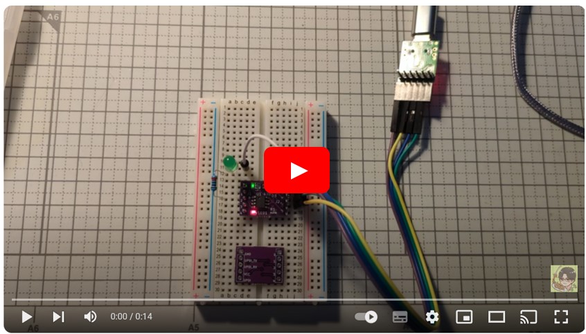
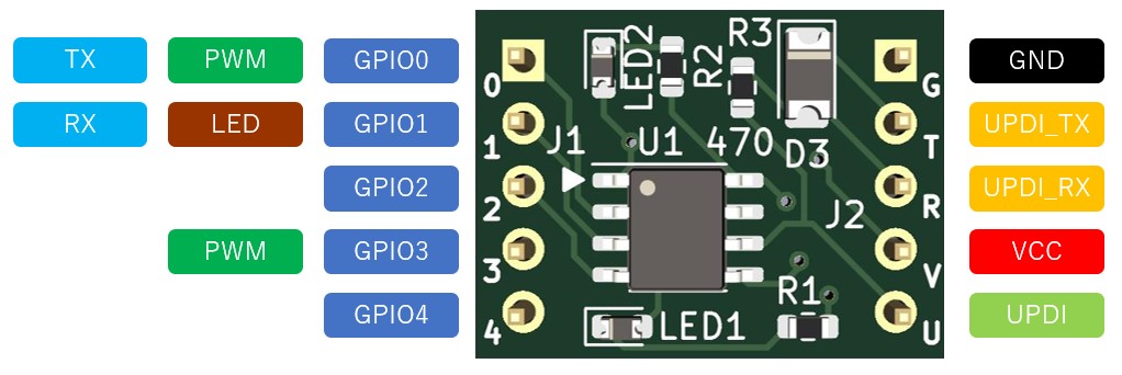
※書き込み用の UPDI_TX、UPDI_RX と Serial 通信用の TX(GPIO0)、RX(GPIO1)があります。
Arduino IDE
Arduino IDE 1 系/2 系で動作確認済み
ただし、ライブラリによっては動作しないものもあります。
RAM が小さいので大規模なプログラムには向きません。
書き込みや Serial Print を使用するには USB シリアル変換モジュールが必要です。
| 部品 | 種類 | 秋月コード | 数量 |
|---|---|---|---|
| 本 PCB | - | ※2 | 1 |
| AVR マイコン ATtiny202 | ATTINY202-SSNR | 115731 | 1 |
| ショットキーバリアダイオード | RB160M-30TR | 101398 | 1 |
| 1608 抵抗 | 1kΩ | 111790 ※1 | 2 |
| 1608 抵抗 | 470Ω | 106471 ※1 | 1 |
| 1608LED | Green | 111878 | 1 |
| 1608LED | Red | 111879 | 1 |
| ピンヘッダ | オスまたはメス | 105779 または 100167 | 5x2 |
※1 ただし、抵抗は Amazon などでセットになったものを入手するほうが安いです
※2 BOOTH(https://toriten51517765.booth.pm/items/5967775)で入手できます。
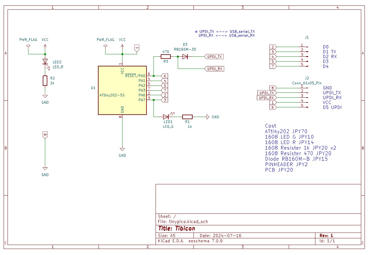
LED とショットキーバリアダイオードは極性があります。
抵抗は極性はありません。
マイコン(ATtiny202)は 1 番ピンの向きに注意してください。
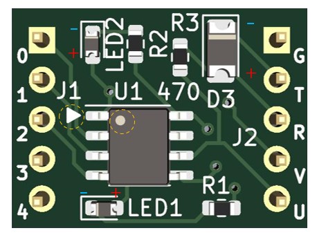
ピンヘッダは好みに応じて、メスピン・オスピン、上向き・下向きが選択可能です。
ピンヘッダをはんだ付けするときは基板に対して垂直になるように気をつけてください。ピン 1 本だけ仮ではんだ付けをして正しく接触していることを確認するとよいです。
ATtiny202 を使用した本マイコンボードは、シリアル UPDI または jtag2updi で書き込みが可能ですが、本プロジェクトではシリアル UPDI を前提として設計しており、こちらを推奨します。
※jtag2updi でも使用可能ですが、外付けの抵抗が必要です。
以下はシリアル UPDI での書き込み方法です。
| 本マイコンボード | シリアル USB |
|---|---|
| UPDI_TX | TX ※ |
| UPDI_RX | RX ※ |
| VCC | VCC |
| GND | GND |
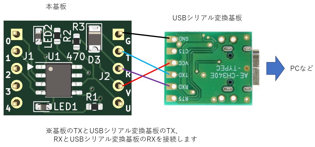
1. Arduino IDE のメニュー「ファイル ¥ 環境設定」より追加のボードマネージャに URL に「http://drazzy.com/package_drazzy.com_index.json」 を追加します。
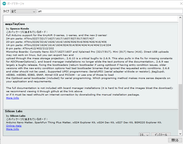
2. 「ツール ¥ ボードマネージャ」より、「megaTinyCore」を追加します。
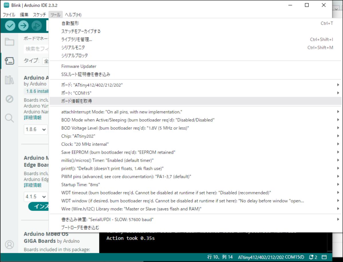
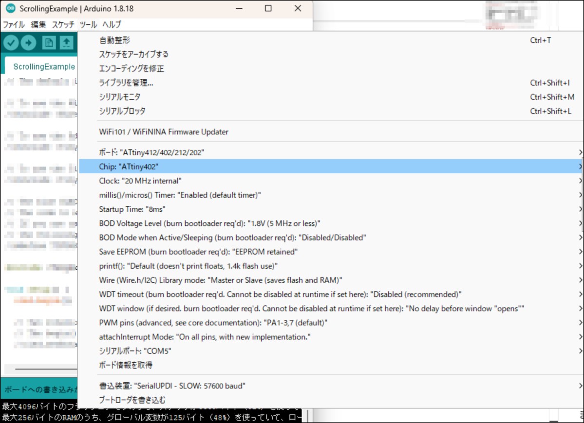
3. 「ツール」より、ボード情報を
4. メニューの「スケッチ ¥ 書き込み装置を使って書き込む」でスケッチを書き込みます。
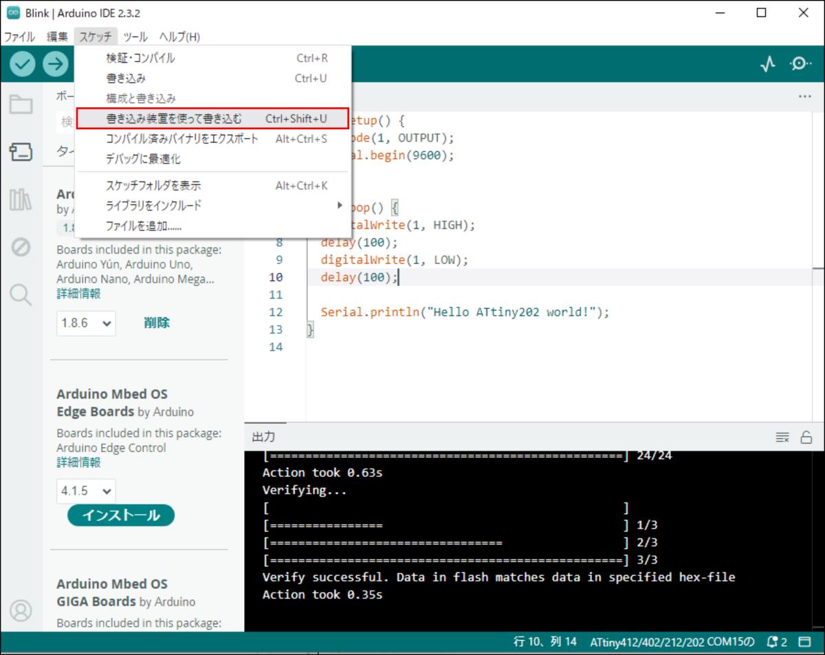
Arduino IDE の 1 系ではいつもと同じようにスケッチを書き込みボタンを押下でも書き込むことが可能です。
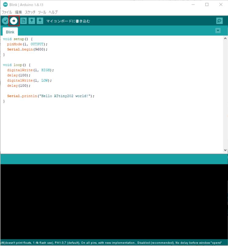
基本は Arduino と同様に使用できます。
Builtin_LED(基板上の赤 LED)はピン番号 1 で使用できます。
※緑 LED は電源ランプで、通電時に点灯します。
void setup() {
  pinMode(1, OUTPUT);
}

void loop() {
  digitalWrite(1, LOW);
  delay(1000);
  digitalWrite(1, HIGH);
  delay(1000);
}
ピン番号(GPIO)は 0 ~ 4 が使用可能です。
本基板では GPIO0 ~ GPIO4 で PWM が使用できます。
GPIO1 ~ GPIO04では通常の Arduino と同じ使い方で使用できますが、GPIO0 では以下のようにコーディングします。
void setup() {
  //GPIO0のセットアップ
  pinMode(0, OUTPUT);
  TCB0.CTRLA = TCB_ENABLE_bm | TCB_CLKSEL_CLKDIV1_gc; //start the timer, set the prescaler to 1
  TCB0.CTRLB = TCB_CCMPEN_bm | TCB_CNTMODE_PWM8_gc; //enable WO0, select the 8 bits PWM mode
  TCB0.CCMPL = 255; //set the PWM resolution to 8 bits
  TCB0.CCMPH = 0; //set the duty cycle
  //GPIO3のセットアップ
  pinMode(3, OUTPUT);
}

void loop()
{
  for (int i = 0; i < 256; i++)
  {
    //GPIO0のPWM
    TCB0.CCMPH = i;
    //GPIO3のPWM
    analogWrite(3,i);
    delay(10);
  }
}本基板では GPIO1 ~ GPIO4 で ADC が使用できます。
通常の Arduino と同じ使い方で使用できます。
void setup() {
  pinMode(1, OUTPUT);
  pinMode(4, INPUT);
}

void loop() {
  //ADC は1,2,3,4が使用可能
  int adc = analogRead(4);
  analogWrite(1, adc);
}USB シリアル変換は内蔵していませんので、外部の USB シリアル変換を使います。
| 本マイコンボード | シリアル USB |
|---|---|
| TX(GPIO0) | RX |
| RX(GPIO1) | TX |
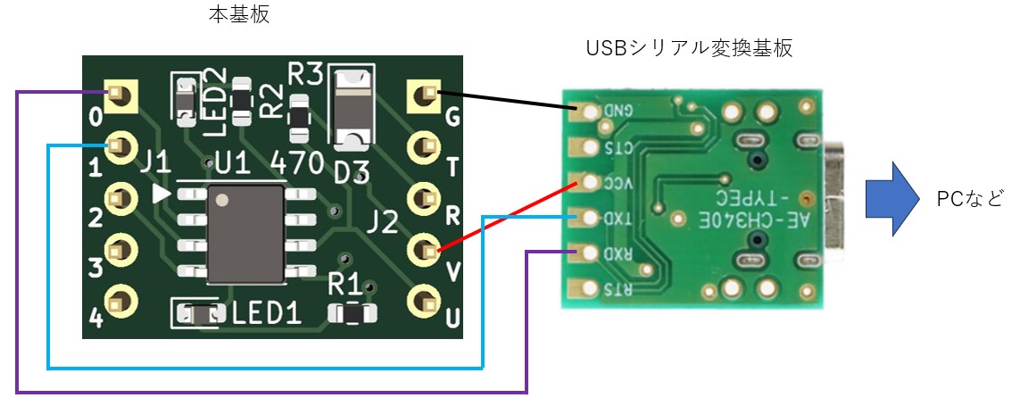 ※図は基板電源をUSBシリアルから給電する場合
Teraterm などで読み取ることができます。Arduino IDE でも読み取ることはできますが、書き込み時と接続が異なりますので USB シリアルの繋ぎ変えが必要になります。
※D1 ピン(Builtin LED)と D2 ピンを共有しているため Serial と同時に使うことはできません。
sample フォルダを参照ください。
ピン互換のATtiny402を使うとフラッシュメモリ容量が2倍になります。
この場合、書きみ手順でChipをATtiny402を選択します。
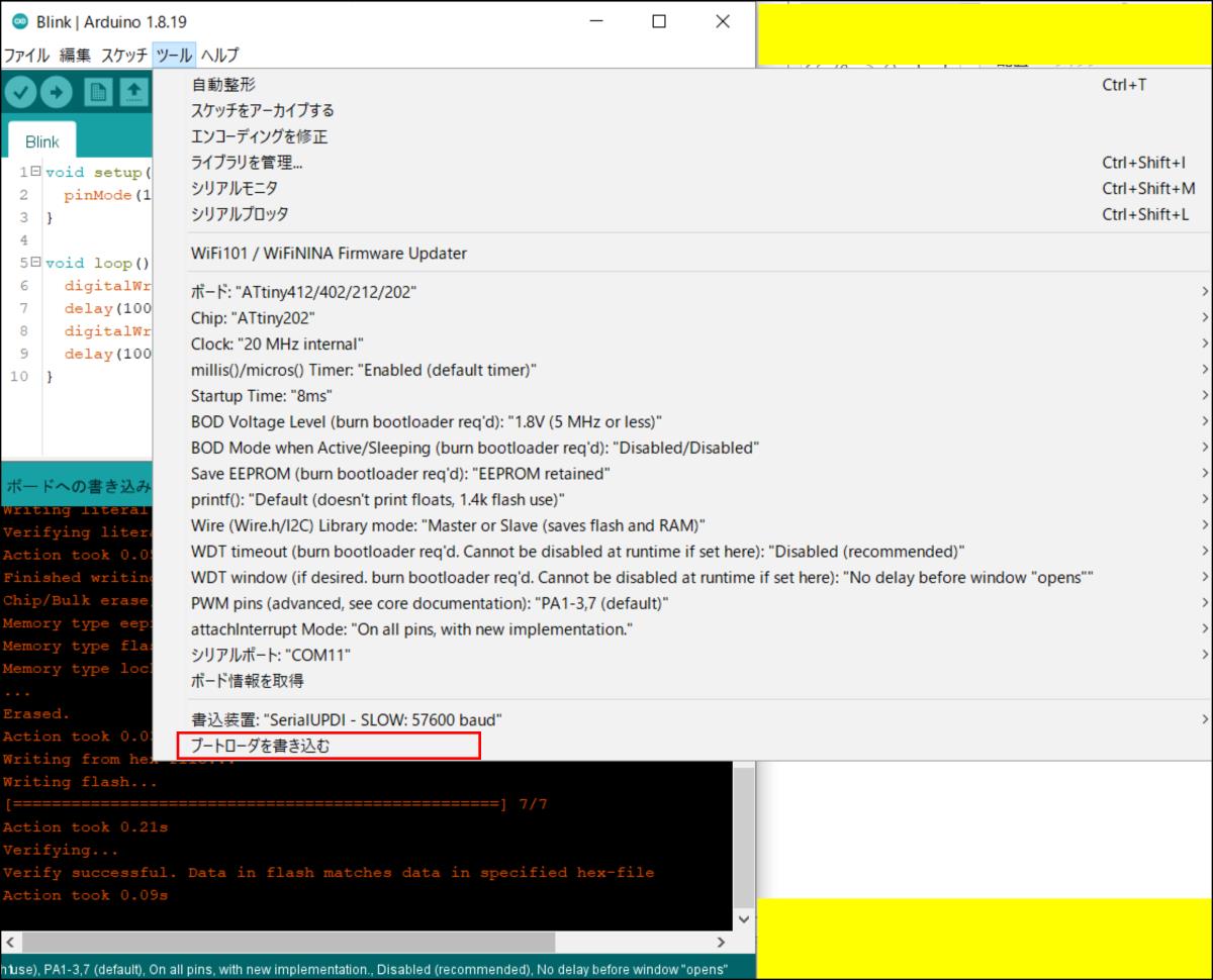
マイコンがおかしくなった時やブートローダーが書き込まれていないマイコンを購入した場合は書き込みが必要になります。Arduino IDE で書き込むことが出来ます。
通常は必要ありません。
Arduino IDEのライブラリとして導入可能なサンプルコードのうち動作確認できたものを追加していきます。
| Library | Name | ATtiny402 | ATtiny202 |
|---|---|---|---|
| Tiny4kOLED | Bitmap | 〇 | × |
| Tiny4kOLED | ScrollingExample | 〇 | × |
| Adafruit NeoPixel | simple | 〇 | × |
This software is released under the MIT License, see LICENSE.
| Qty | Value | Footprint | References |
|---|---|---|---|
| 420 | NPTH | NPTH | KiKit_MB_10_3, KiKit_MB_10_4, KiKit_MB_10_5, KiKit_MB_10_6, KiKit_MB_10_7, KiKit_MB_11_3, KiKit_MB_11_4, KiKit_MB_11_5, KiKit_MB_11_6, KiKit_MB_11_7, KiKit_MB_12_3, KiKit_MB_12_4, KiKit_MB_12_5, KiKit_MB_12_6, KiKit_MB_12_7, KiKit_MB_13_3 +404 |
| 40 | 1k | Resistor_SMD:R_0603_1608Metric | R1, R1, R1, R1, R1, R1, R1, R1, R1, R1, R1, R1, R1, R1, R1, R1 +24 |
| 40 | Conn_01x05_Pin | Connector_PinHeader_2.54mm:PinHeader_1x05_P2.54mm_Vertical | J1, J1, J1, J1, J1, J1, J1, J1, J1, J1, J1, J1, J1, J1, J1, J1 +24 |
| 20 | ATtiny202-SS | Package_SO:SOIC-8_3.9x4.9mm_P1.27mm | U1, U1, U1, U1, U1, U1, U1, U1, U1, U1, U1, U1, U1, U1, U1, U1 +4 |
| 20 | LED_G | Diode_SMD:D_0603_1608Metric | LED1, LED1, LED1, LED1, LED1, LED1, LED1, LED1, LED1, LED1, LED1, LED1, LED1, LED1, LED1, LED1 +4 |
| 20 | LED_R | Diode_SMD:D_0603_1608Metric | LED2, LED2, LED2, LED2, LED2, LED2, LED2, LED2, LED2, LED2, LED2, LED2, LED2, LED2, LED2, LED2 +4 |
| 20 | R3 | Resistor_SMD:R_0603_1608Metric | 470, 470, 470, 470, 470, 470, 470, 470, 470, 470, 470, 470, 470, 470, 470, 470 +4 |
| 20 | RB160M-30 | Diode_SMD:D_1206_3216Metric | D3, D3, D3, D3, D3, D3, D3, D3, D3, D3, D3, D3, D3, D3, D3, D3 +4 |

freeDSP/FreeDSP_Catamaran_AB
A mono contruction Differntial 1 Input 4 output ADAU1701 DSP board, 96kHz TDM8 interlink is available.


CyberPit/FreeDSP_Classic_SMD_AB_plus-II
An extended version of FreeDSP Classic SMD A/B

CyberPit/FreeDSP-FreeDSP_SMD_AB
2in4out ADAU1701 Board with selectable 2 EEPROMs, SMD resisitors, ThtoughHole Ele-Caps.

cazacov/PocketComputers
My experiments with programmable calculators and pocket computers

aezrapour/RINSIGHT
This version was an attempt to use a 2S battery pack. The main issue is that as of 2022-09-15, there are not many 2S battery charging IC's nor a nice i2C fuel gauge IC, so at the moment, this is a dead end design.


It measures 96 × 92.5 mm and has 2 copper layers, 1.4 mm thick.
600 parts, built around the ATTINY202-SSN and RB160M-30. The full list of its parts is on this page, with links to each part's symbol and footprint where PCBKit's library has them.
From the s51517765/Tibicon repository on GitHub, at the commit this page was made from: the board is pcb/panelize/panelize.kicad_pcb and its schematic pcb/panelize/panelize.kicad_sch. PCBKit opens the board in the browser, with nothing to install.
Its repository publishes it under the MIT licence: you may reuse it on that licence's terms (keep the author's notice, and for a copyleft licence share your changes alike).