2 layers30 × 29.3 mm
PRJ
Juniper-Rueter/PR-J
A universal load cell amplifier for communication with klipper and an open standard for strain gauges
24 parts17

 AnOrdinaryUsername/attiny202-dev-board
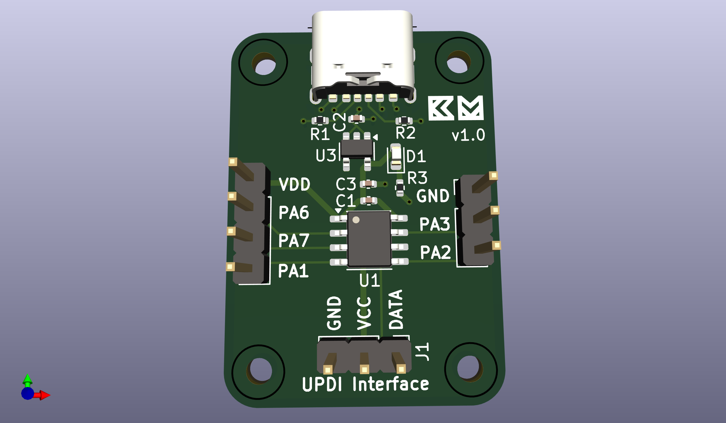
A small development board for the ATtiny202 microcontroller and my first PCB!
Attiny202-dev board is an open-source printed circuit board by AnOrdinaryUsername, from the AnOrdinaryUsername/attiny202-dev-board repository on GitHub. It is a 2-layer board of 24 × 33.5 mm with 19 parts on 13 nets, routed with 70 tracks and 12 vias.
It is built around the ATTINY202-SSN and MIC5365-3.3YD5-TR. Its parts include 4 connectors, 3 capacitors, 3 resistors, 2 ICs and 1 diode. It belongs with the microcontroller boards boards and the AVR (ATmega, ATtiny) boards of this library.


A small development board for the ATtiny202 microcontroller and my first PCB!
Programmable using SerialUPDI (recommended) or jtag2updi.
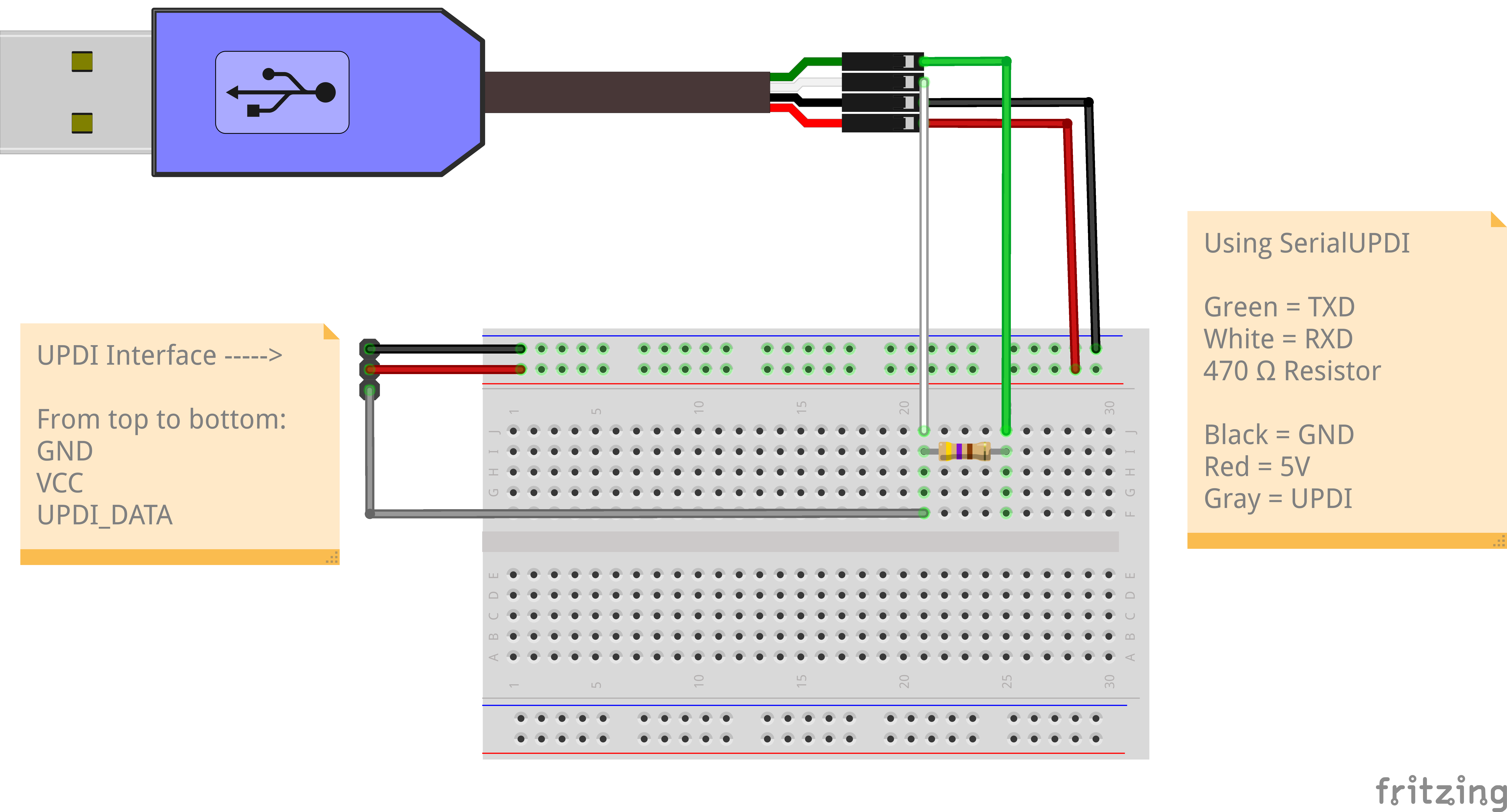
Install avrdude following these instructions on their GitHub. Don't install through your system's package manager, or you'll get an older version of avrdude that doesn't have SerialUPDI.
Before you can use avr-gcc to build the program, you must first download the device-pack files
from Microchip's Packs Repository. Download the one that
says Microchip ATtiny Series Device Support (3.1.260) and then unzip it to a directory of your
choice.
mkdir atpack
mv Microchip.ATtiny_DFP.3.1.260.atpack atpack
cd atpack && unzip Microchip.ATtiny_DFP.3.1.260.atpack
You can now build specific projects using the Makefile
make build proj=blinky atpack=~/atpack/Or build all projects
makeAfter you've built your project and connected the USB to TTL adapter to your PC and the UPDI interface, upload the build files using avrdude.
avrdude -vvv -c serialupdi -b 230400 -P /dev/ttyUSB0 -p t202 -U flash:w:your_build_file.hex:aBreaking it down (better explanation at avrdude docs):
-vvv Enables verbose output-c Specifies the programmer to be used-b Sets the baud rate-P Selects which port to use-p Says which microcontroller we're programming for (t202 stands for ATtiny202). You can view the list of parts supported at D. List of Parts-U Write the hex file to flash memory and auto-detect the file format (usually Intel Hex)Alternatively, you can also use the Makefile:
make upload proj=blinky port=/dev/ttyUSB0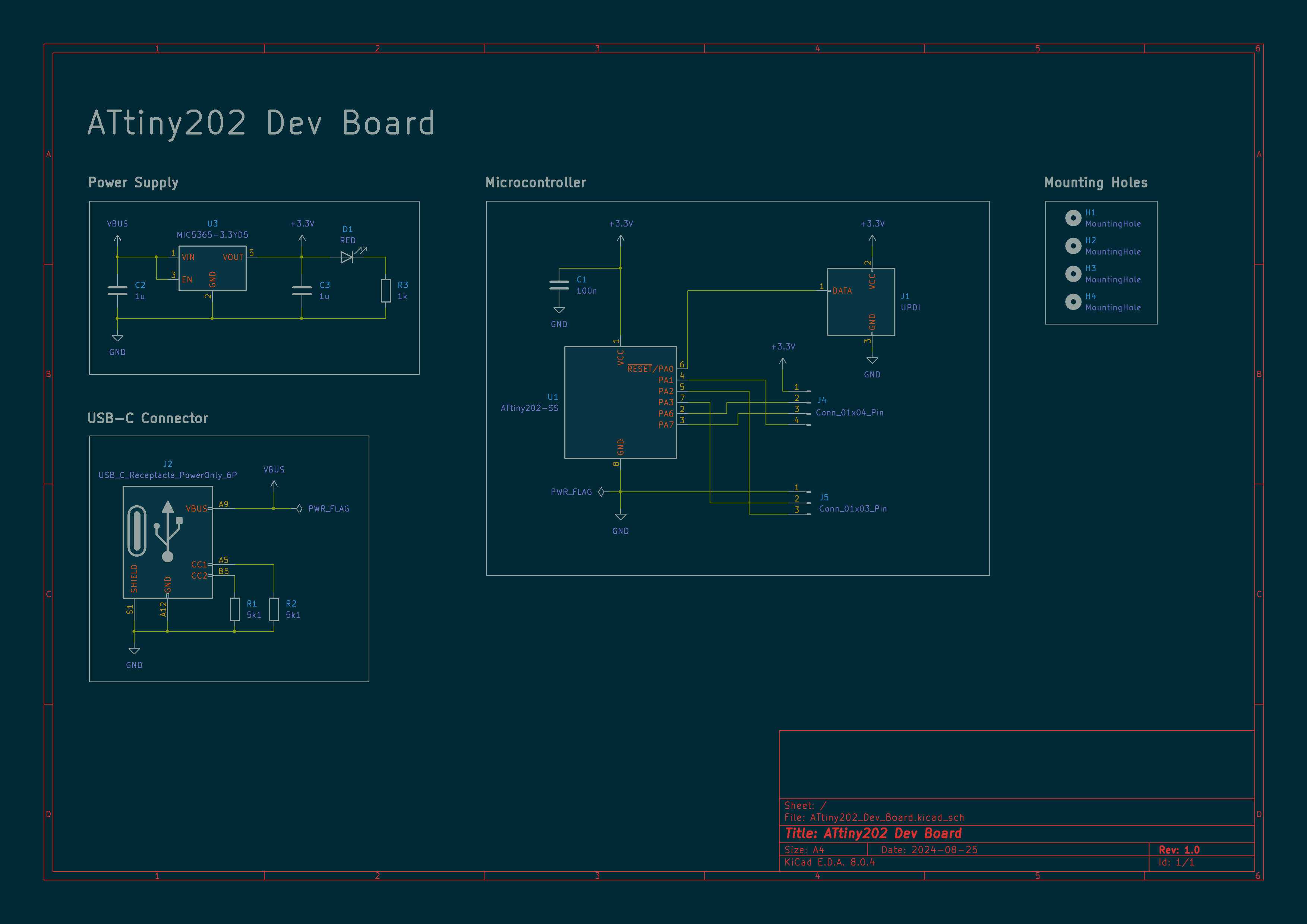
JLCPCB formatted BOM, CPL, and Gerber files can be found in hardware.
Here's how the fully assembled PCB looks.
| Top | Bottom |
|---|---|
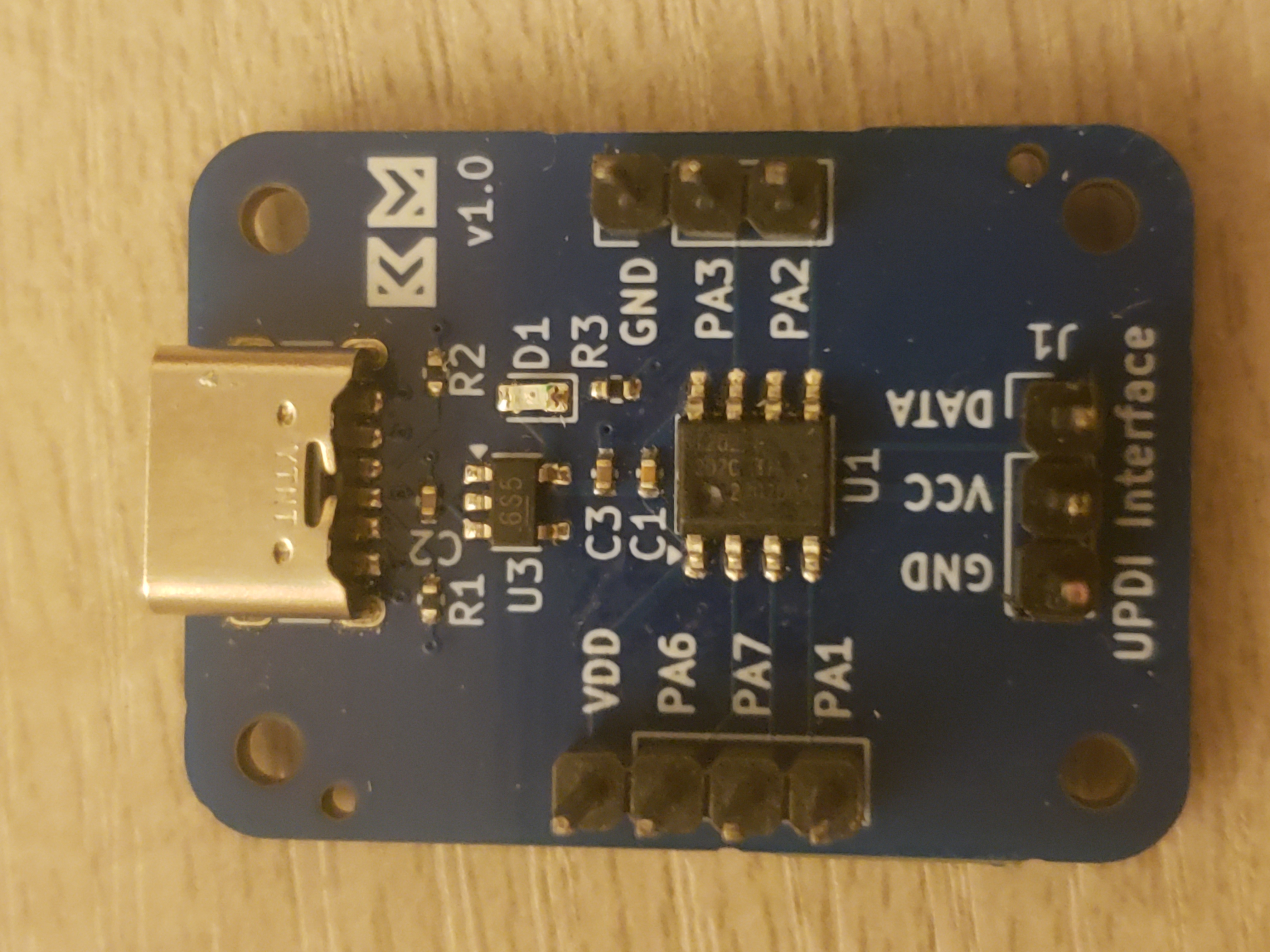 | 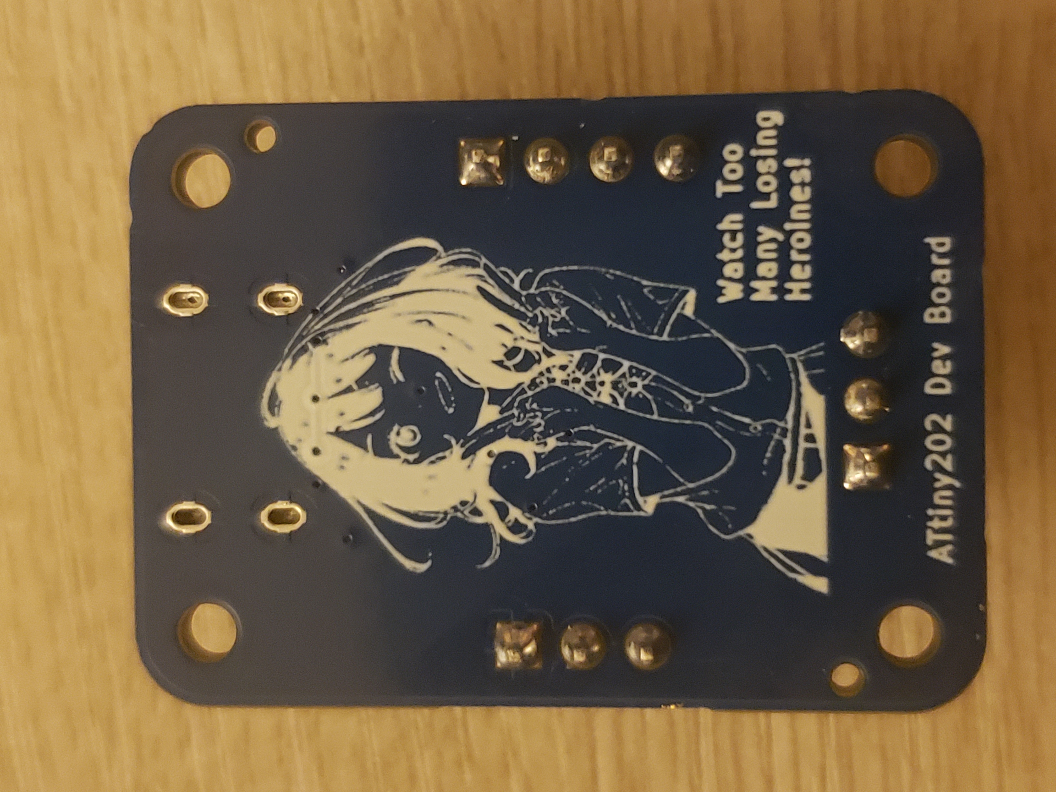 |
| Qty | Value | Footprint | References |
|---|---|---|---|
| 4 | MountingHole | MountingHole:MountingHole_2.2mm_M2 | H1, H2, H3, H4 |
| 2 | 1u | Capacitor_SMD:C_0402_1005Metric | C2, C3 |
| 2 | 5k1 | Resistor_SMD:R_0402_1005Metric | R1, R2 |
| 2 | LOGO | LOGO | G***, G*** |
| 1 | 100n | Capacitor_SMD:C_0402_1005Metric | C1 |
| 1 | 1k | Resistor_SMD:R_0402_1005Metric | R3 |
| 1 | ATtiny202-SS | Package_SO:SOIC-8_3.9x4.9mm_P1.27mm | U1 |
| 1 | Conn_01x03_Pin | Connector_PinHeader_2.54mm:PinHeader_1x03_P2.54mm_Vertical | J5 |
| 1 | Conn_01x04_Pin | Connector_PinHeader_2.54mm:PinHeader_1x04_P2.54mm_Vertical | J4 |
| 1 | MIC5365-3.3YD5 | Package_TO_SOT_SMD:SOT-23-5 | U3 |
| 1 | RED | LED_SMD:LED_0603_1608Metric | D1 |
| 1 | UPDI | Connector_PinHeader_2.54mm:PinHeader_1x03_P2.54mm_Vertical | J1 |
| 1 | USB_C_Receptacle_PowerOnly_6P | Connector_USB:USB_C_Receptacle_GCT_USB4125-xx-x_6P_TopMnt_Horizontal | J2 |
Juniper-Rueter/PR-J
A universal load cell amplifier for communication with klipper and an open standard for strain gauges

Dlloydev/Updi-Key
This DIY open source hardware connects inline with any UPDI programmer to provide a HV UPDI programming solution for tinyAVR® 0/1/2 series MCUs.

IamPhytan/christmas-tree-pcb
Christmas Tree PCB, made with FOSS


akita11/SolenoidStrokeUNIT
Grove端子にUART通信元(M5Stack等のマイコンやUSBシリアル変換器)を接続し、本UNITに対してコマンド送信や結果の受信を行います。Grove端子の信号は、"RXD(受信) / TXD(送信) / VDD(+5V) /…

It measures 24 × 33.5 mm and has 2 copper layers, 1.6 mm thick.
19 parts, built around the ATTINY202-SSN and MIC5365-3.3YD5-TR. The full list of its parts is on this page, with links to each part's symbol and footprint where PCBKit's library has them.
From the AnOrdinaryUsername/attiny202-dev-board repository on GitHub, at the commit this page was made from: the board is hardware/ATtiny202_Dev_Board.kicad_pcb and its schematic hardware/ATtiny202_Dev_Board.kicad_sch. PCBKit opens the board in the browser, with nothing to install.
Its repository states no licence, so its author keeps all rights: ask AnOrdinaryUsername before reusing the design.