2 layers131.2 × 95.7 mm
Swadge S2-Devkit
AEFeinstein/Super-2023-Swadge-HW
Swadge devkit for an ESP32-S2 with all the bells and whistles
86 parts17MIT
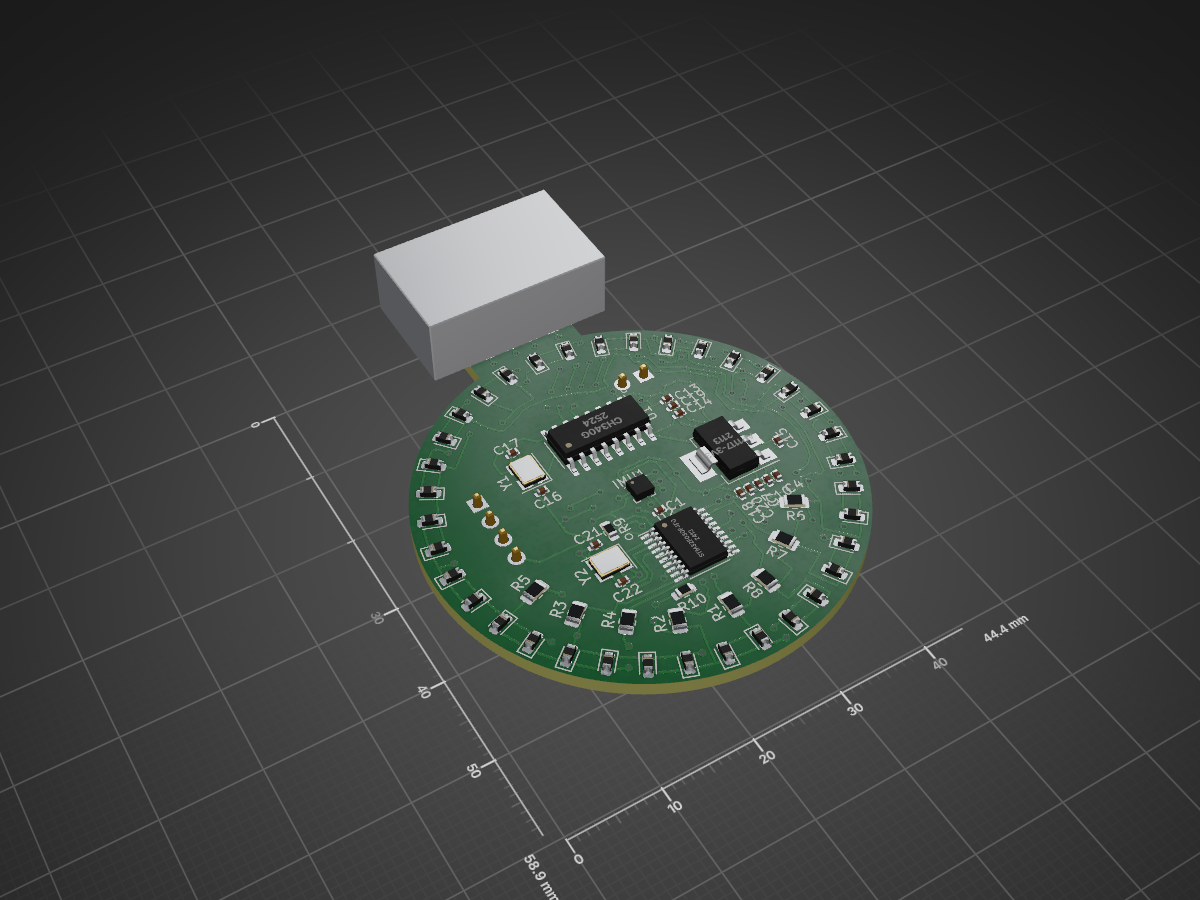
 WingTechCorner/WTC_PROJECT-XMAS-USB-ORNAMENT1
A little cool XMAS project
JLCPCB HOLIDAY PROJECT is an open-source printed circuit board by WingTechCorner, from the WingTechCorner/WTC_PROJECT-XMAS-USB-ORNAMENT repository on GitHub. It is a 2-layer board of 12.1 × 36.7 mm with 70 parts on 42 nets, routed with 860 tracks and 102 vias.
It is built around the STM32F030F4P6, CH340G and QMA7981. Its parts include 36 diodes, 14 capacitors, 10 resistors, 3 ICs and 2 crystals. It belongs with the sensors and measurement boards and the STM32 boards of this library.


** ISSUE - Design Seems To produce non-working unit. Investigating... **
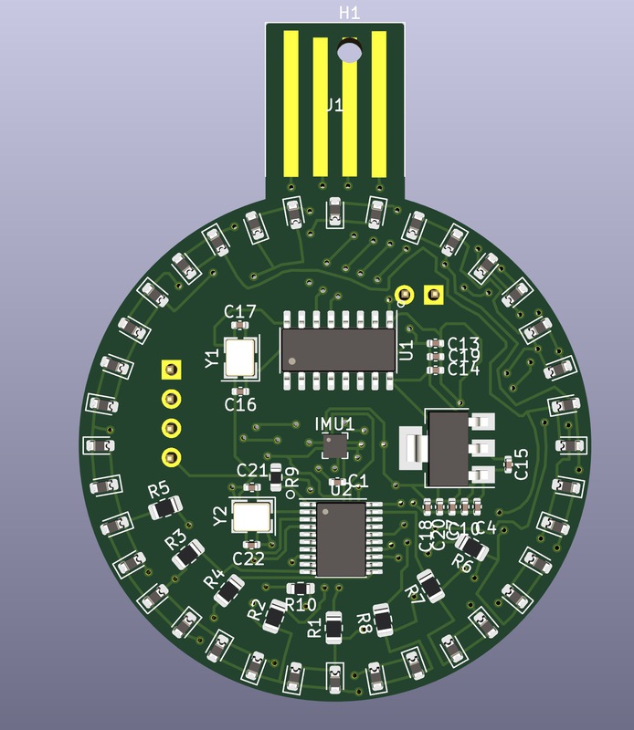
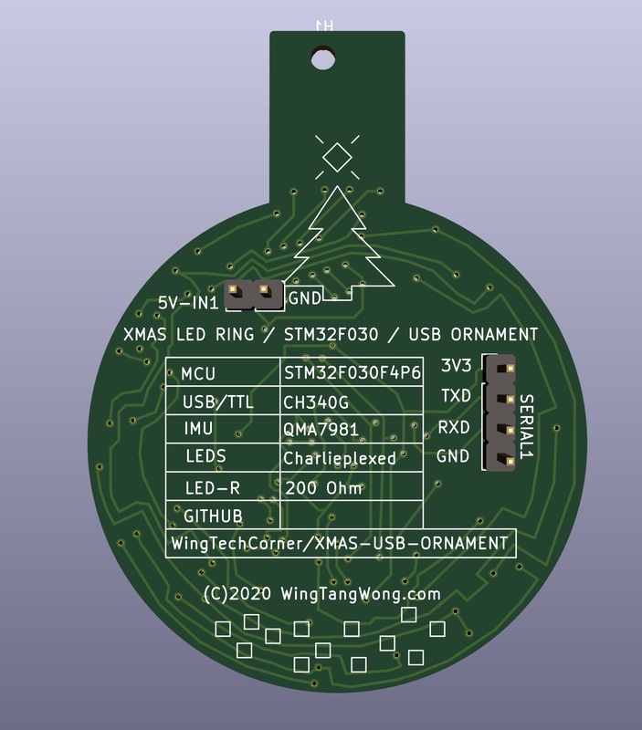
This is a project I'm also submitting to the JLCPCB.com Holiday Contest!
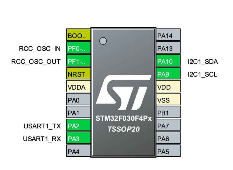
The code is setup as a platformio project. To build:
# To compile/build
pio run

# To upload (Note, assumes serial upload)
pio run --target=upload| Qty | Value | Footprint | References |
|---|---|---|---|
| 36 | BLUE_LED | Diode_SMD:D_0603_1608Metric | D1, D2, D10, D11, D12, D13, D14, D15, D16, D17, D18, D19, D20, D21, D22, D23 +20 |
| 8 | 200Ohms-±1%-1_8W-0805 | Resistor_SMD:R_0805_2012Metric | R1, R2, R3, R4, R5, R6, R7, R8 |
| 7 | 100nF-16V-0402 | Capacitor_SMD:C_0402_1005Metric | C1, C4, C7, C10, C13, C14, C19 |
| 4 | 12pF-50V-0402 | Capacitor_SMD:C_0402_1005Metric | C16, C17, C21, C22 |
| 3 | 1uF-25V-0402 | Capacitor_SMD:C_0402_1005Metric | C15, C18, C20 |
| 2 | 12mhz-Crystal_GND24 | Crystal:Crystal_SMD_TXC_7M-4Pin_3.2x2.5mm | Y1, Y2 |
| 2 | 4.7KOhms-±1%-1_10W-0603 | Resistor_SMD:R_0603_1608Metric | R9, R10 |
| 1 | AP1117-3v3 | Package_TO_SOT_SMD:SOT-223-3_TabPin2 | U3 |
| 1 | CH340G | KiCad-Library-JLCPCB:SOIC-16_3.9x9.9mm_P1.27mm_JLC_ROTATED | U1 |
| 1 | Conn_01x02_Male | Connector_PinHeader_2.54mm:PinHeader_1x02_P2.54mm_Vertical | 5V-IN1 |
| 1 | Conn_01x04_Male | Connector_PinHeader_2.54mm:PinHeader_1x04_P2.54mm_Vertical | SERIAL1 |
| 1 | MountingHole | MountingHole:MountingHole_2.2mm_M2 | H1 |
| 1 | QMA7981 | KiCad-Library-JLCPCB:LGA-12_2x2mm_P0.5mm | IMU1 |
| 1 | STM32F030F4P6 | Package_SO:TSSOP-20_4.4x6.5mm_P0.65mm | U2 |
| 1 | USB_A_PCB | KiCad-Library-JLCPCB:USB-A-PCB | J1 |
AEFeinstein/Super-2023-Swadge-HW
Swadge devkit for an ESP32-S2 with all the bells and whistles


rusefi/hellen-miata-NB2
a rusEFI board with a 72 pin connector. Works for a Mazda Miata NB2 or any generic 8 cylinder vehicle :)

cnlohr/cnhardware
My dumping grounds for all my kicad projects and random hardware bringup.


marcelobarrosufu/brewbuddy
Thermometer, stopwatch, step mash tool, boiling and hop additions controller in a compact instrument !

It measures 12.1 × 36.7 mm and has 2 copper layers, 1.6 mm thick.
70 parts, built around the STM32F030F4P6, CH340G and QMA7981. The full list of its parts is on this page, with links to each part's symbol and footprint where PCBKit's library has them.
From the WingTechCorner/WTC_PROJECT-XMAS-USB-ORNAMENT repository on GitHub, at the commit this page was made from: the board is Hardware/JLCPCB-HOLIDAY-PROJECT.kicad_pcb. PCBKit opens the board in the browser, with nothing to install.
Its repository states no licence, so its author keeps all rights: ask WingTechCorner before reusing the design.