2 layers321.5 × 116.7 mm
 UWARG/hardware59
PCB designs for the Waterloo Aerial Robotics Group
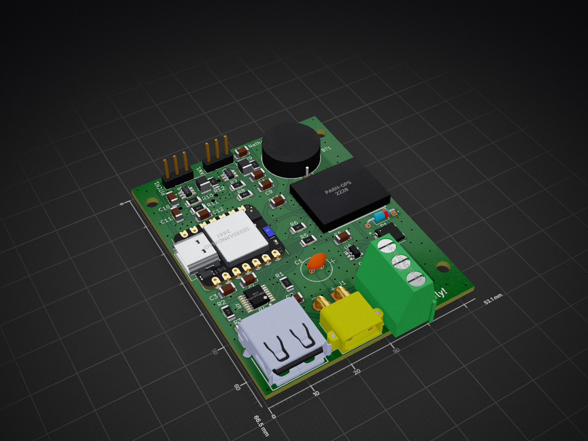
Arduino AAT is an open-source printed circuit board by UWARG, from the UWARG/hardware repository on GitHub. It is a 2-layer board of 53.1 × 66.5 mm with 43 parts on 53 nets, routed with 320 tracks and 228 vias.
It is built around the TPS563201DDCR, FT230XS-R and AS7805ADTR-G1, with the MIC5504-3.3YM5, 1N4148TR and COM-16347 among its other parts. Its parts include 13 capacitors, 12 resistors, 7 ICs, 2 diodes and 2 connectors. It belongs with the robots and motor control boards and the SAM D and SAM boards of this library.


This repository previously held WARG electricals designs (Altium Schematics, PCBs, & Libraries) from roughly 2021 to 2022. In mid 2022 we switched solely toward Altium 365, https://warg.365.altium.com/ , and have largely abandonned this repository. Ideally we would upload completed projects to this Github for safe keeping in case anything happens with our Altium 365. For further documentation see Confluence, https://uwarg-docs.atlassian.net/wiki/spaces/EL/overview , or our team Discord.

| Qty | Value | Footprint | References |
|---|---|---|---|
| 5 | 10k | Resistor_SMD:R_1206_3216Metric | R4, R7, R8, R10, R12 |
| 4 | 22uF | Capacitor_SMD:C_1206_3216Metric | C8, C9, C11, C12 |
| 2 | 0.1uF | Capacitor_SMD:C_1206_3216Metric | C7, C10 |
| 2 | 220R | Resistor_SMD:R_1206_3216Metric | R5, R6 |
| 2 | 27R | Resistor_SMD:R_1206_3216Metric | R1, R2 |
| 2 | 3.3uF | Inductor_SMD:L_1210_3225Metric | L1, L2 |
| 2 | 47pF | Capacitor_SMD:C_1206_3216Metric | C2, C3 |
| 2 | 47uF | Capacitor_SMD:C_1206_3216Metric | C5, C6 |
| 2 | 54.9k | Resistor_SMD:R_1206_3216Metric | R9, R11 |
| 2 | Conn_01x03_Pin | Connector_PinHeader_2.54mm:PinHeader_1x03_P2.54mm_Vertical | PITCH1, YAW1 |
| 2 | TPS563201DDCR | TPS563201DDCR:SOT95P280X110-6N | U3, U4 |
| 1 | 100nF | Capacitor_SMD:C_1206_3216Metric | C4 |
| 1 | 1N4148TR | 1N4148TR:DIOAD753W49L380D172B | D1 |
| 1 | 1uF | Capacitor_SMD:C_1206_3216Metric | C13 |
| 1 | 220uF | 25YXJ220M6.3X11:CAP_YX_6P3X11_RUB | C1 |
| 1 | 4k7 | Resistor_SMD:R_1206_3216Metric | R3 |
| 1 | AS7805ADTR-G1 | AS7805ADTR-G1:DPAK457P1010X238-3N | U2 |
| 1 | Battery_Cell | BH-98R-1:BH-98R-1_ADM | BT1 |
| 1 | COM-16347 | COM-16347:COM-16347_SPK | LED1 |
| 1 | INTERFACE-FT230XS-R_SSOP16_ | FT230XS-R:SSOP16-0.635-5X4MM | U7 |
| 1 | LOGO | bateman:warg | G*** |
| 1 | LOGO | bateman:bateman_phone | G*** |
| 1 | MIC5504-3.3YM5 | Package_TO_SOT_SMD:SOT-23-5 | U6 |
| 1 | PA6H-GPS | PA6H:PA6H-GPS | U5 |
| 1 | SeeeduinoXIAO | Seeeduino_XIAO:Seeeduino XIAO-MOUDLE14P-2.54-21X17.8MM | U1 |
| 1 | USB-A1HSW6 | USB-A1HSW6:OST_USB-A1HSW6 | P1 |
| 1 | XT30PW-M | XT30PW-M:AMASS_XT30PW-M | J1 |

Takingo/Mypcb35
OmniCircuit AI is a local proof of concept for an autonomous PCB/PCBA design and manufacturing suite. The current implementation focuses on the ESP32-S3 + DWM3000 UWB Anchor example and establishes the architecture for:

SolderedElectronics/Breadboard-power-supply-board-hardware-design
Hardware design, BOM, gerbers and 3D files for Breadboard-power-supply-board designed by Soldered Electronics.

TPierceUCSD/Wireless-motion-capture-data-sycnhronization-system
© 2025 Taylor Pierce, Emerson Noble, Lucas Davis, Jesus Wilkins, Kenneth J. Loh. Licensed under CC BY 4.0.

7903555032/AERIS-H743-PCB
A 6-layer STM32H743-based embedded development and flight-control/data-logging PCB designed as a practical hardware-design and PCB-layout project.

WojciechM98/Home-assistant-ESP32
Home assistand board using ESP32 controlled with MQTT protocol.

ThunderFly-aerospace/TFSBEC01
High efficient switching power supply for UAV actuators.


idpromnut/mDotBuddy
A support PCB that allows for powering and logging of an mDot from Multitech either via on-board FTDI or an external FTDI cable.
It measures 53.1 × 66.5 mm and has 2 copper layers, 1.6 mm thick.
43 parts, built around the TPS563201DDCR, FT230XS-R, AS7805ADTR-G1 and MIC5504-3.3YM5. The full list of its parts is on this page, with links to each part's symbol and footprint where PCBKit's library has them.
From the UWARG/hardware repository on GitHub, at the commit this page was made from: the board is Projects/Arduino_AAT/Arduino_AAT.kicad_pcb and its schematic Projects/Arduino_AAT/Arduino_AAT.kicad_sch. PCBKit opens the board in the browser, with nothing to install.
Its repository states no licence, so its author keeps all rights: ask UWARG before reusing the design.