4 layers108 × 110 mm
 UPNAdrone/JavaFAWT2
Open-source fan array wind tunnel (FAWT) software and hardware
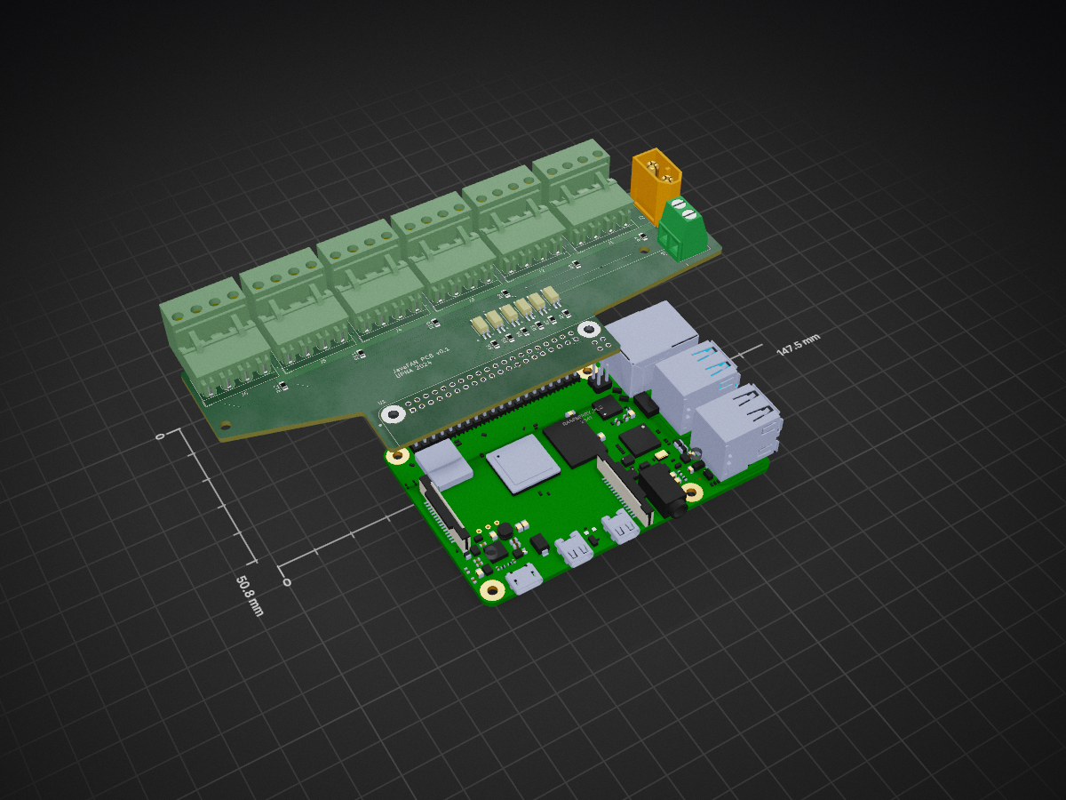
Prueba is an open-source printed circuit board by UPNAdrone, from the UPNAdrone/JavaFAWT repository on GitHub, published under the Apache-2.0 licence. It is a 2-layer board of 147.5 × 50.8 mm with 27 parts on 57 nets, routed with 200 tracks and 10 vias.
It is built around the HMHA2801AR2 and XT60-M. Its parts include 12 resistors, 8 connectors, 6 transistors and 1 IC.

JavaFAWT is a fan-array-wind tunnel (FAWT) open-source software and hardware architecture developed by the drones lab of Universidad Pública de Navarra. It includes diagrams and PCB layouts for electronics, CAD designs for hardware, and source files for running and adapting the software.

The proposed control scheme follows a wireless server-client architecture. A Java GUI is provided for the control station (server) to connect and command each fan, organized in series of modules. Each module is managed by a single Raspberry Pi client (currently tested with Raspberry Pi 3, 4, Zero 2 w), which receives the fan speed control messages from the server via a wireless WebSocket. The client receives the message, identifies its connected fans, and converts the speed signal to a PWM output for each fan, allowing for precise individual control of an indefinite number of fans. Thanks to the custom PCB interface, an external power supply can be used for each module, and a single control power source is used to elevate the 3.3V PWM control signal for each and every fan up to a standard required voltage.
Bill of Materials (BOM) can be found here
PCB Manufacturing project can be found here
Detailed instructions for installing and running the software can be found here.
A Tutorial/Manual of use can be found here.
Our recorded dataset consists of approximately 45,176 samples recorded with our experimental 6x4 wind tunnel. It includes two CSV files: one for relative pressures (directly extracted from the nanoDAQ LTS-32 pressure scanner readings), one for velocities (extracted by converting the relative pressure, temperature and density values to velocity). The dataset can be found in Hugging Face: https://huggingface.co/datasets/UPNAdrone/WindTunnel
JavaFAWT is made available under the MIT License. You are free to use, modify, and distribute this module in accordance with the terms of the MIT License.
If you use this module for research, please consider citing our paper to acknowledge its contribution:
@article{pending,
  title={},
  author={},
  journal={},
  volume={},
  pages={},
  year={},
  publisher={}
}
| Qty | Value | Footprint | References |
|---|---|---|---|
| 12 | R | Resistor_SMD:R_0805_2012Metric_Pad1.20x1.40mm_HandSolder | R1, R2, R3, R4, R5, R6, R7, R8, R9, R10, R11, R12 |
| 6 | HMHA2801AR2 | KiCAD:MFP4_100AL_OSI-M | Q1, Q2, Q3, Q4, Q5, Q6 |
| 6 | Screw_Terminal_01x04 | TerminalBlock_MetzConnect:TerminalBlock_MetzConnect_Type011_RT05504HBWC_1x04_P5.00mm_Horizontal | J1, J2, J3, J4, J5, J6 |
| 1 | RASPBERRY_PI_3_MODEL_B_ | RASPBERRY_PI_3_MODEL_B_:MODULE_RASPBERRY_PI_3_MODEL_B_ | U1 |
| 1 | Screw_Terminal_01x02 | TerminalBlock_MetzConnect:TerminalBlock_MetzConnect_Type011_RT05502HBWC_1x02_P5.00mm_Horizontal | J8 |
| 1 | XT60-M | XT60-M:AMASS_XT60-M | J7 |

pms67/HadesFCS
Complete flight control system designed from scratch. Hardware designed with KiCad.

GonzaCerv/noah-hardware
This repo contains all the hardware description for the Noah project. Here lies 3D models, electronics PCB and Firmware software of the robot.


edromufu/edromufu
Repositório da EDROM-UFU destinado ao desenvolvimento do projeto humanoide para participação nas competições LARC e ROBOCUP.


kairobyte/bipedal_self_balance
A bipedal self balancing robot with 2DOF in each leg. Built from scratch.

It measures 147.5 × 50.8 mm and has 2 copper layers, 1.6 mm thick.
27 parts, built around the HMHA2801AR2 and XT60-M. The full list of its parts is on this page, with links to each part's symbol and footprint where PCBKit's library has them.
From the UPNAdrone/JavaFAWT repository on GitHub, at the commit this page was made from: the board is hardware/module/electronics/prueba.kicad_pcb and its schematic hardware/module/electronics/prueba.kicad_sch. PCBKit opens the board in the browser, with nothing to install.
Its repository publishes it under the Apache-2.0 licence: you may reuse it on that licence's terms (keep the author's notice, and for a copyleft licence share your changes alike).