
2 layers80 × 110 mm
NucDeck Left Controller PCB
dmcke5/NucDeck
The Open Source DIY Handheld Gaming PC!
59 parts561CERN-OHL-S-2.0

 TimGoll/pcb_atmega328pb
The board's design is heavily based on the design of the Arduino Uno. All the USB communication stuff was removed. The board is therefore reduced to its bare minimum.
Atmega isp is an open-source printed circuit board by TimGoll, from the TimGoll/pcb_atmega328pb repository on GitHub. It is a 2-layer board of 58.4 × 69.9 mm with 27 parts on 35 nets, routed with 311 tracks and 211 vias.
It is built around the ATMEGA328P-AU. Its parts include 9 connectors, 7 capacitors, 2 resistors, 1 IC and 1 diode. It belongs with the AVR (ATmega, ATtiny) boards of this library.
The board's design is heavily based on the design of the Arduino Uno. All the USB communication stuff was removed. The board is therefore reduced to its bare minimum. The most notable deviation in comparison to the Arduino Uno is that my board uses a 20MHz crystal.
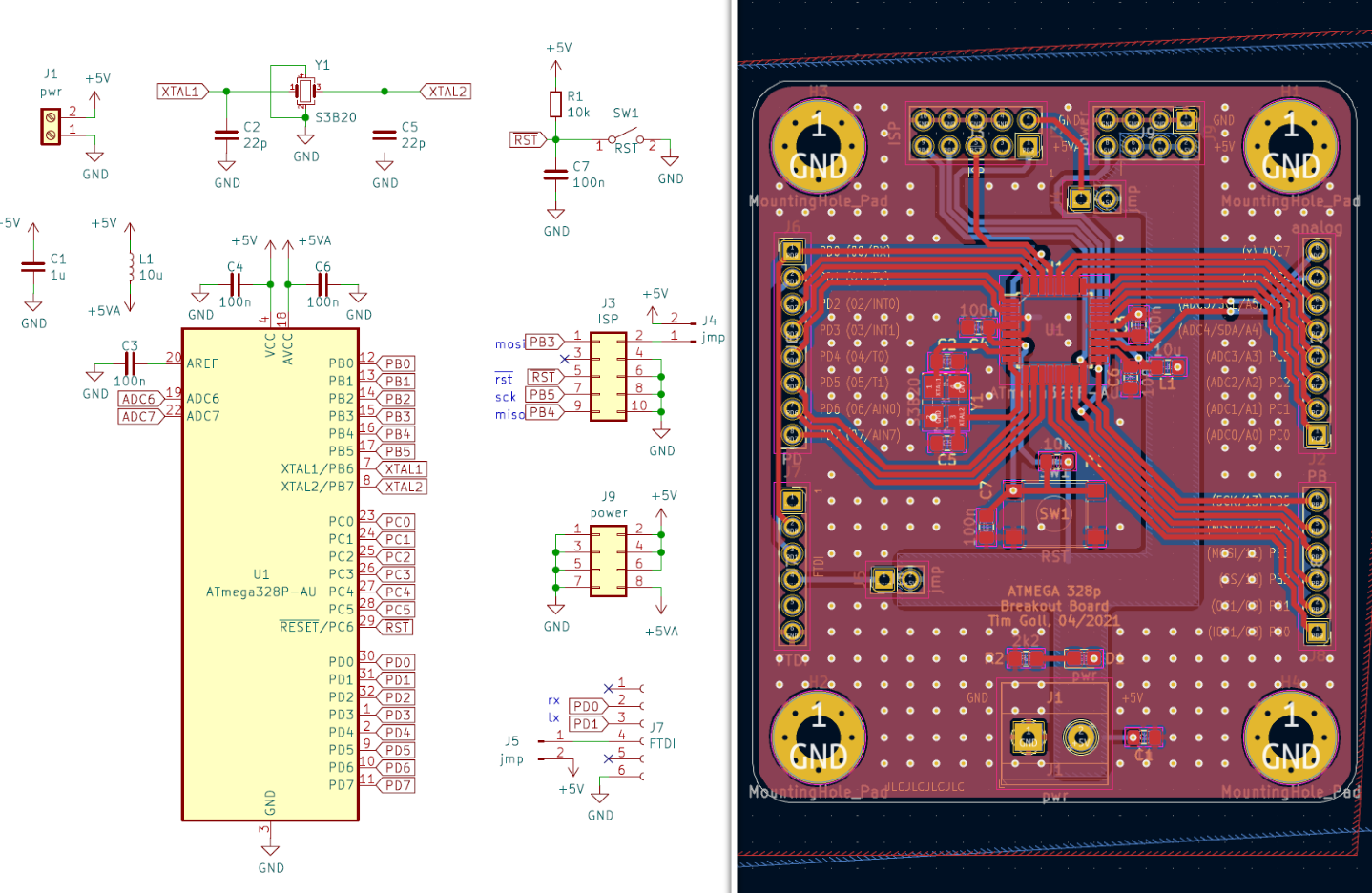 (The schematic and the PCB I created from this schematic)
The board is a two layer design with mostly ground planes that are stitched together with multiple vias. All the relevant parts are mounted to the front side.
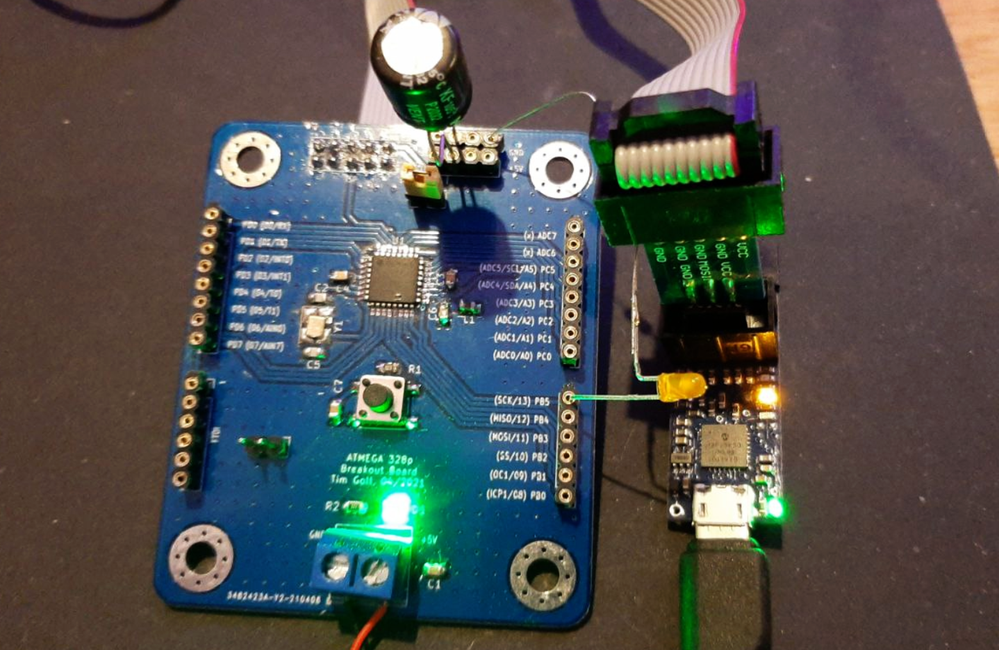 (The finished PCB aith the programmer next to it)
The design of the board works like intended with the one issue, that the ISP connector is mirrored. This however is fixed in the current version in this repository.
This board has to be programmed with an ISP connection located on the board. There are different programmers available, I'm using the Pololu USB AVR Programmer v2.1. The driver package should be installed as it comes with a nice tool to look at the programmer.
A working programmer looks something like this. Do note here that I'm using an external power supply for the MCU here.
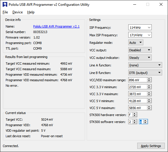
If the board is connected, avrdude can be used to read the info of the MCU. Use ./avrdude.exe in the command line while being in the correct folder, for me it is: C:\Program Files (x86)\Arduino\hardware\tools\avr\bin.
Use the following command to read the board information:
./avrdude.exe -C ../etc/avrdude.conf -c stk500 -P COM8 -b 19200 -p m328pb -vCOM8 is used here because it is the programming port of this programmer, stk500 is the type of the programmer. See this article for more information on this.
To use an external crystal, the fuses of the board have to be set. The fuse bits can be easily set with the AVR fuse calculator. They then have to be flashed to the board. The command is mostly the same, only the -v gets replaced by the fuse byte command from the website.
Now the board can be flashed with the desired software. There are different ways to do this, but if the Arduino IDE should be used, a few things have to be set up.
First MiniCore has to be added as it features a few more missing AVRs with UI based configurability. The json file link had to be added in the Arduino Settings page as described in the project's readme.
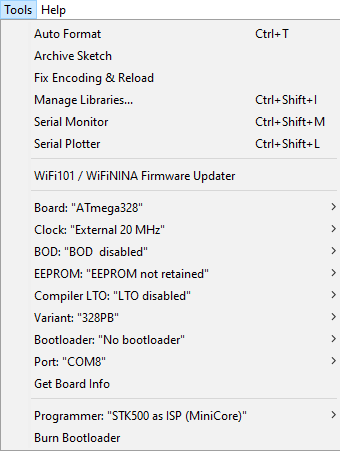
These are the settings that were used here for this specific board setup. It can be easily verified by uploading a simple LED blink sketch.
| Qty | Value | Footprint | References |
|---|---|---|---|
| 4 | 100n | Capacitor_SMD:C_0805_2012Metric_Pad1.15x1.40mm_HandSolder | C3, C4, C6, C7 |
| 4 | MountingHole_Pad | MountingHole:MountingHole_4.3mm_M4_Pad_Via | H1, H2, H3, H4 |
| 2 | 22p | Capacitor_SMD:C_0805_2012Metric_Pad1.15x1.40mm_HandSolder | C2, C5 |
| 2 | jmp | Connector_PinHeader_2.54mm:PinHeader_1x02_P2.54mm_Vertical | J4, J5 |
| 1 | 10k | Resistor_SMD:R_0805_2012Metric_Pad1.15x1.40mm_HandSolder | R1 |
| 1 | 10u | Inductor_SMD:L_0805_2012Metric_Pad1.15x1.40mm_HandSolder | L1 |
| 1 | 1u | Capacitor_SMD:C_0805_2012Metric_Pad1.15x1.40mm_HandSolder | C1 |
| 1 | 2k2 | Resistor_SMD:R_0805_2012Metric_Pad1.15x1.40mm_HandSolder | R2 |
| 1 | ATmega328P-AU | Package_QFP:TQFP-32_7x7mm_P0.8mm | U1 |
| 1 | FTDI | Connector_PinSocket_2.54mm:PinSocket_1x06_P2.54mm_Vertical | J7 |
| 1 | ISP | Connector_PinSocket_2.54mm:PinSocket_2x05_P2.54mm_Vertical | J3 |
| 1 | PB | Connector_PinHeader_2.54mm:PinHeader_1x06_P2.54mm_Vertical | J8 |
| 1 | PD | Connector_PinHeader_2.54mm:PinHeader_1x08_P2.54mm_Vertical | J6 |
| 1 | RST | Button_Switch_SMD:SW_Push_1P1T_NO_6x6mm_H9.5mm | SW1 |
| 1 | S3B20 | Crystal:Crystal_SMD_3225-4Pin_3.2x2.5mm_HandSoldering | Y1 |
| 1 | analog | Connector_PinHeader_2.54mm:PinHeader_1x08_P2.54mm_Vertical | J2 |
| 1 | power | Connector_PinHeader_2.54mm:PinHeader_2x04_P2.54mm_Vertical | J9 |
| 1 | pwr | LED_SMD:LED_0805_2012Metric_Castellated | D1 |
| 1 | pwr | TerminalBlock_Phoenix:TerminalBlock_Phoenix_MKDS-1,5-2-5.08_1x02_P5.08mm_Horizontal | J1 |
dmcke5/NucDeck
The Open Source DIY Handheld Gaming PC!


profdc9/RFBitBanger
A QRP digital transceiver created from readily available parts for off-the-grid maintenance

futureshocked/KLP4e_MCU-Datalogger
This is the repository for the "MCU Datalogger" project.


sportiduino/sportiduino
Electronic timing system for orienteering and similar outdoor sports events on Arduino

SukkoPera/OpenPSX2AmigaPadAdapter
Playstation to Commodore Amiga/CD32 Controller Adapter

4x1md/vx8_gps
DIY GPS module for Yaesu VX-8DR/VX-8DE handheld transceiver.
It measures 58.4 × 69.9 mm and has 2 copper layers, 1.6 mm thick.
27 parts, built around the ATMEGA328P-AU. The full list of its parts is on this page, with links to each part's symbol and footprint where PCBKit's library has them.
From the TimGoll/pcb_atmega328pb repository on GitHub, at the commit this page was made from: the board is atmega_isp/atmega_isp.kicad_pcb and its schematic atmega_isp/atmega_isp.kicad_sch. PCBKit opens the board in the browser, with nothing to install.
Its repository states no licence, so its author keeps all rights: ask TimGoll before reusing the design.