

4 layers99 × 53.3 mm
PSLab
fossasia/pslab-hardware
PSLab Hardware Design and Schematics https://pslab.io
199 parts1.7kApache-2.0

 TheTesla/rotary-encoder-protection
Connector with protection circuit for rotary encoders
Rotary encoder protection is an open-source printed circuit board by TheTesla, from the TheTesla/rotary-encoder-protection repository on GitHub, published under the CERN-OHL-S-2.0 licence. It is a 2-layer board of 38.5 × 29.8 mm with 18 parts on 9 nets, routed with 49 tracks and 3 vias.
It is built around the BZV55B24 and 1N4148W. Its parts include 5 resistors, 4 diodes, 3 connectors and 2 capacitors.
The rotary encoders don't have any electrical protection mechanism. Overcurrent into the open collector outputs will damage them.
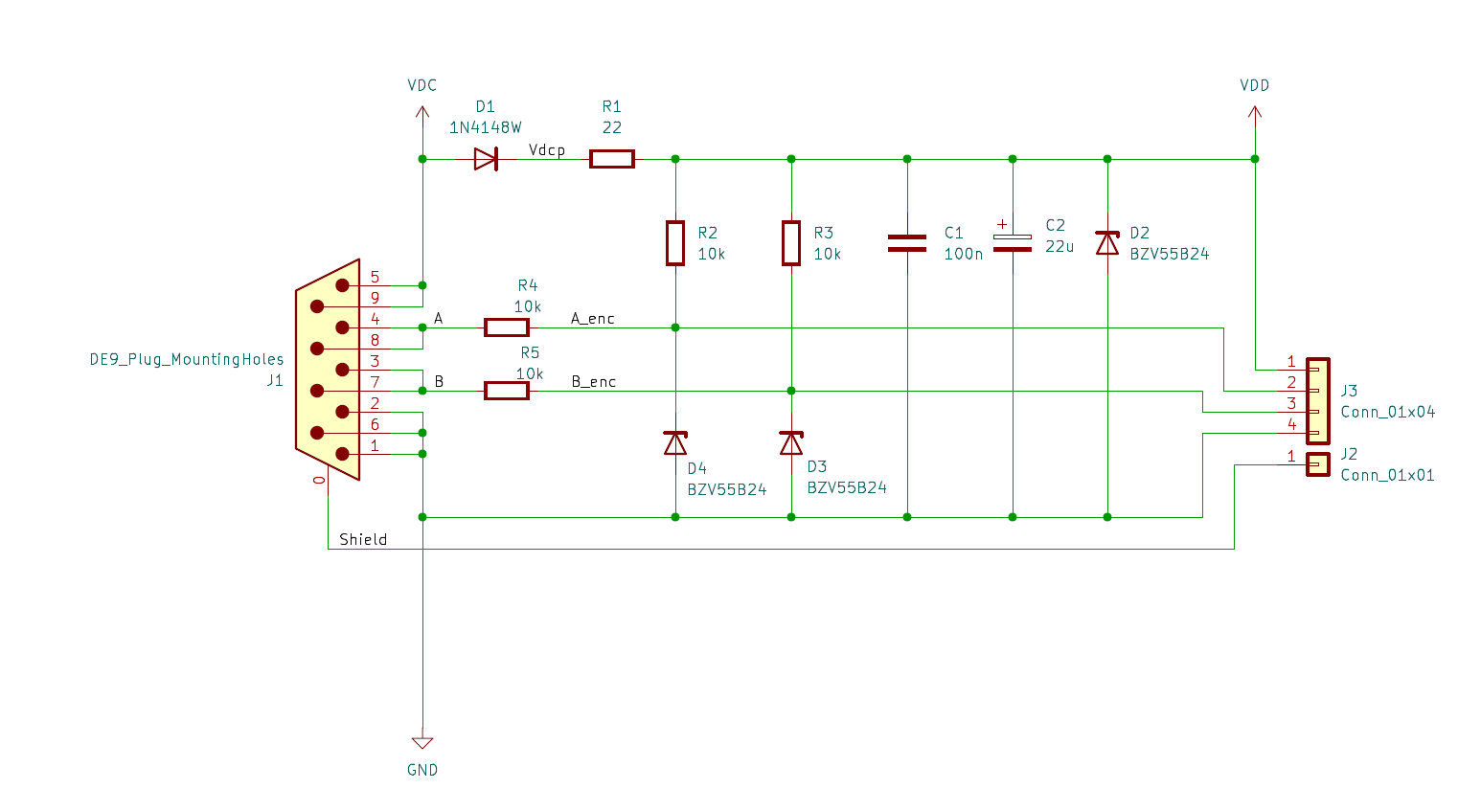
This board protects the rotary encoder against reverse polarity and short overvoltage spikes on the power supply line. Each data line is protected using a 10k resistor in series. Pull-up resistors are incooperated on the encoder side. That means, the board outputs are directly high impedance logic level. External voltage to these data pins won't damage the encoder or protection board.
Direct connection to ICs with a low voltage tolerance at the inputs is possible, because the clamp diodes in the IC will limit the voltage from the high impedance outputs of the board.
That protection board is part of the plug at the rotary encoder cable. It is intended to be connected to the logic board, which implements the data processing:
Stefan Helmert stefan.helmert@htw-dresden.de
The PCB without case and without rotary encoder:
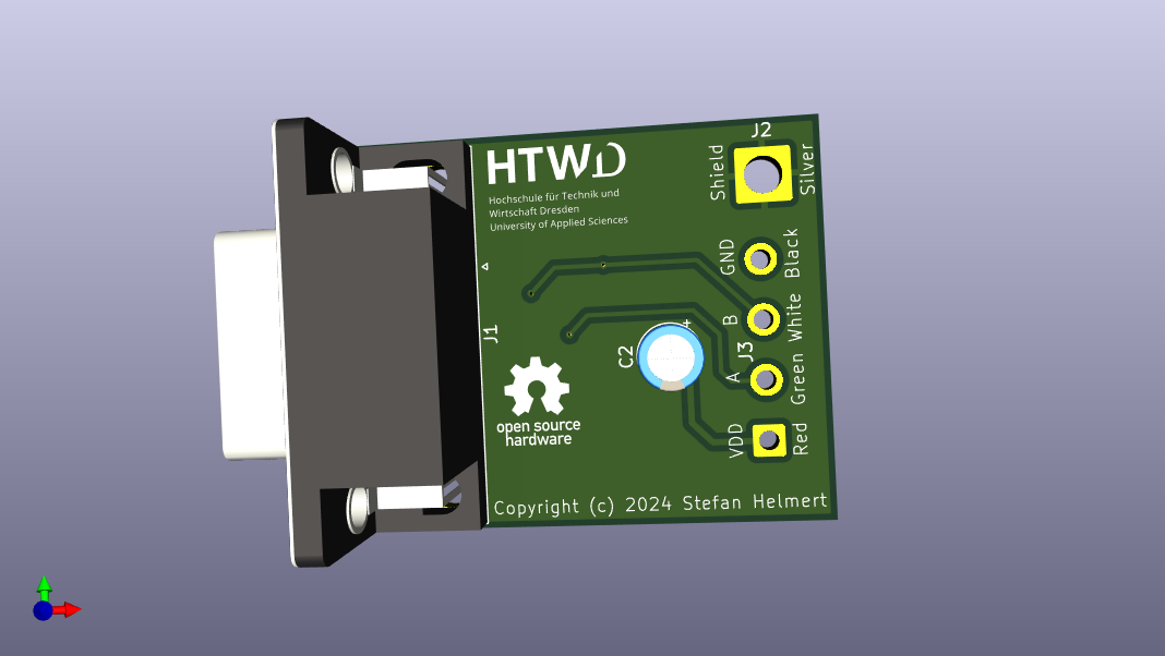
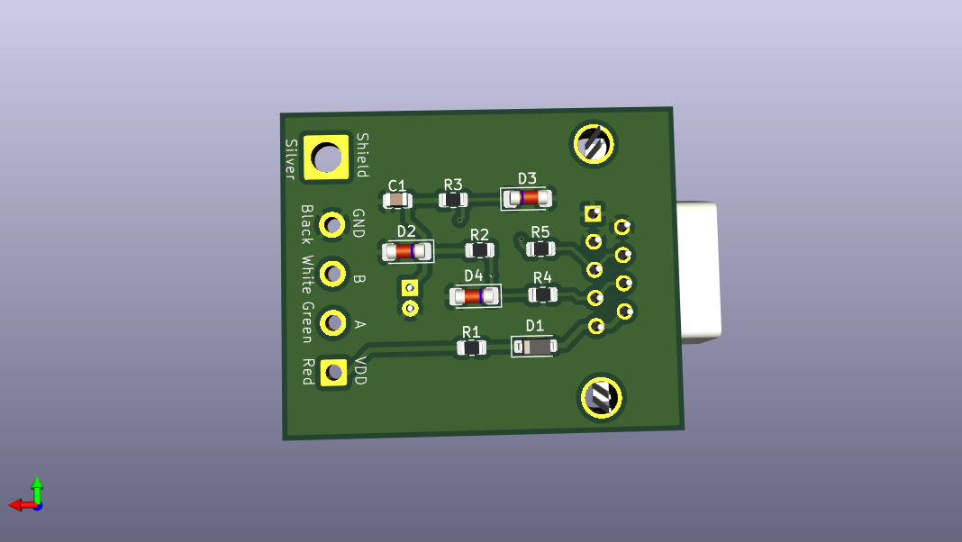
| Qty | Value | Footprint | References |
|---|---|---|---|
| 4 | 10k | Resistor_SMD:R_0805_2012Metric | R2, R3, R4, R5 |
| 4 | MountingHole_Pad | MountingHole:MountingHole_2.7mm_M2.5_ISO14580_Pad_TopBottom | H1, H2, H3, H4 |
| 3 | BZV55B24 | Diode_SMD:D_MiniMELF | D2, D3, D4 |
| 1 | 100n | Capacitor_SMD:C_0805_2012Metric | C1 |
| 1 | 1N4148W | Diode_SMD:D_SOD-123 | D1 |
| 1 | 22 | Resistor_SMD:R_0805_2012Metric | R1 |
| 1 | 22u | Capacitor_THT:CP_Radial_D5.0mm_P2.00mm | C2 |
| 1 | Conn_01x01 | Connector_Wire:SolderWire-2.5sqmm_1x01_D2.4mm_OD4.4mm | J2 |
| 1 | Conn_01x04 | Connector_Wire:SolderWire-0.75sqmm_1x04_P4.8mm_D1.25mm_OD2.3mm | J3 |
| 1 | DE9_Plug_MountingHoles | Connector_Dsub:DSUB-9_Pins_Horizontal_P2.77x2.84mm_EdgePinOffset7.70mm_Housed_MountingHolesOffset9.12mm | J1 |
fossasia/pslab-hardware
PSLab Hardware Design and Schematics https://pslab.io

pierrechevalier83/ferris
A low profile split keyboard designed to satisfy one single use case elegantly


MickiusMousius/Rolio46Keyboard
A split wireless keyboard based on the Corne and Sofle


sadekbaroudi/bgkeeb
This is a reversible 100mm x 100mm pcb with support for mx or choc switches (no hotswap), per key led, rotary encoders, and exposes the SDA/SCL/GND/VCC lines in the form of the pimoroni trackball pins (meaning you can…

It measures 38.5 × 29.8 mm and has 2 copper layers, 1.6 mm thick.
18 parts, built around the BZV55B24 and 1N4148W. The full list of its parts is on this page, with links to each part's symbol and footprint where PCBKit's library has them.
From the TheTesla/rotary-encoder-protection repository on GitHub, at the commit this page was made from: the board is src/elec/RotaryEncoderProtection.kicad_pcb and its schematic src/elec/RotaryEncoderProtection.kicad_sch. PCBKit opens the board in the browser, with nothing to install.
Its repository publishes it under the CERN-OHL-S-2.0 licence: you may reuse it on that licence's terms (keep the author's notice, and for a copyleft licence share your changes alike).