2 layers90.2 × 109.9 mm
Circuit pcb
Testbild-synth/super-sweet-16
Deluxe 16-step knob-per-function sequencer Module for eurorack
162 parts12MIT

 Testbild-synth/super-sweet-1612
Deluxe 16-step knob-per-function sequencer Module for eurorack
Circuit pcb smd dac is an open-source printed circuit board by Testbild-synth, from the Testbild-synth/super-sweet-16 repository on GitHub, published under the MIT licence. It is a 2-layer board of 90.2 × 109.9 mm with 163 parts on 148 nets, routed with 777 tracks and 48 vias.
It is built around the MCP4728-E/UN and BAT43. Its parts include 52 diodes, 38 resistors, 24 connectors, 16 switches and 4 ICs. It belongs with the audio and music boards of this library.


For a while now I've been looking for a through hole diy eurorack sequencer that is as hands-on as the Baby8 but with comfort features you would maybe not have with an analog/cmos design. The outcome of my struggle is this module. It is a 16-step sequencer with the following functions:
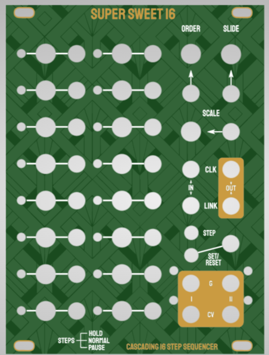
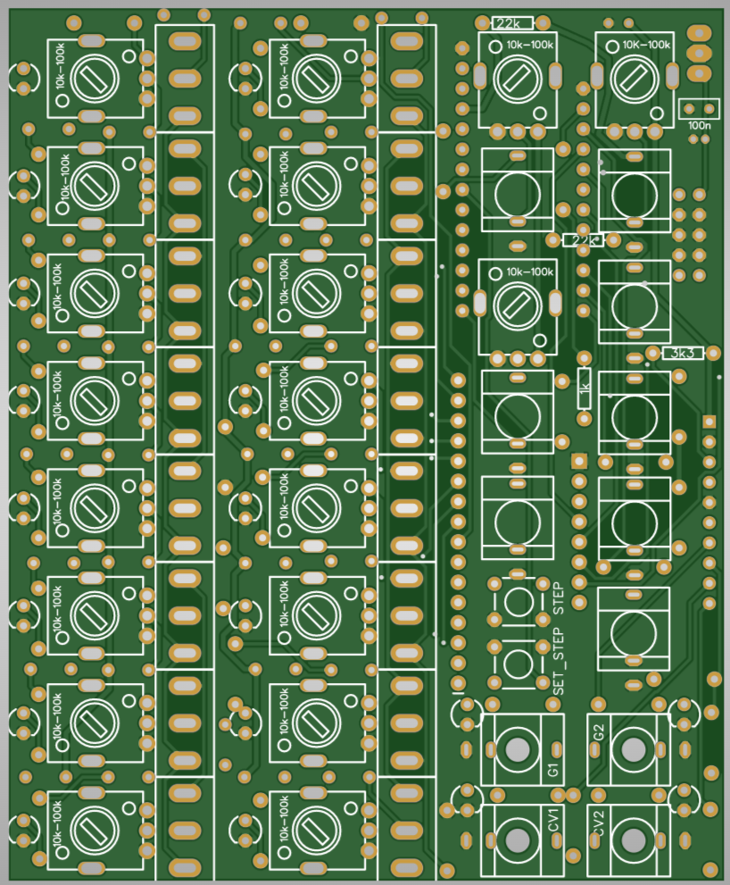
I really wanted this to go on one pcb and while its a bit cramped, it works and I think the build is still doable. the panel is 19hp, which is kind of a weird size. If people message me about it I might change it to 20 so that there's a bit more space between knobs but for now I'm fine like this.
you need three ICs:
For the build, I would suggest you go in the following order:
you can order the pcbs as is with the gerbers provided from any pcb service, I use jlc. Make sure to use leadfree surface finish for the panel as you will be touching silver areas. I still have a bunch of PCBs and panels leftover, if you're in the EU and don't wanna order yourself I can sell you a set :)
code subfolder contains finished arduino sketch.
for your arduino to compile and upload properly you need the adafruit_4728 library and the Analog-digital-multiplexers library (https://docs.arduino.cc/libraries/analog-digital-multiplexers/).
To make 16 channels and per-step switches work with an arduino nano and one mux on one pcb, I had to cut a few corners. The result is that if you have cold solder joints or some contacts are not soldered perfectly you might have a bit of MUX crosstalk (meaning that the frequency at which the mux is switched is so high that there is leftover charge from the last reading). To check, do the following:
Mine is fine as is but you can increase the CROSSTALK_DELAY_MS variable in the code. this might decrease crosstalk but increase latency. If you still get problems, redo all solder joints. If you still get problems after that tell me and we can talk about changing some resistors, but as I said mine works as is so this might not be needed.
Basic operation:
Menu: Press and hold "reset step" to get into menu mode. Now you can change the following parameters:
| Qty | Value | Footprint | References |
|---|---|---|---|
| 32 | BAT43 | easyeda:DIODE | D1, D2, D10, D11, D12, D13, D14, D15, D16, D17, D18, D19, D20, D21, D22, D23 +16 |
| 24 | AutoGenerated:Pad_2.00mm | , , , , , , , , , , , , , , , +8 | |
| 20 | LED TBR | easyeda:LED-3MM/2.54 | LED1, LED2, LED3, LED4, LED5, LED10, LED11, LED12, LED13, LED14, LED15, LED16, LED17, LED18, LED19, LED20 +4 |
| 18 | 10-100k | easyeda:R09-5KΩ | P1, P2, P3, P4, P5, P6, P7, P8, P9, P10, P11, P12, P13, P14, P15, P16 +2 |
| 16 | 10k | easyeda:R_AXIAL-0.3 | R1, R2, R3, R4, R5, R6, R7, R8, R9, R10, R11, R12, R13, R14, R15, R16 |
| 16 | SPDT | easyeda:TOGGLE SWITCH SPDT RED 3 PIN ON-OFF-ON 3 SPDT SMALL AC 6A/125V 3A/250V | S1, S2, S3, S4, S5, S6, S7, S8, S9, S10, S11, S12, S13, S14, S15, S16 |
| 7 | 22k | easyeda:R_AXIAL-0.3 | R17, R18, R19, R26, R27, R28, R29 |
| 5 | 1k | easyeda:R_AXIAL-0.3 | R24, R25, R30, R33, R34 |
| 4 | 4.7k | easyeda:R_AXIAL-0.3 | R22, R23, R31, R32 |
| 2 | 100n | easyeda:RAD-0.1 | C2, C3 |
| 2 | 3k3 | easyeda:R_AXIAL-0.3 | R20, R21 |
| 1 | AutoGenerated:Pad_1.50mm | ||
| 1 | AutoGenerated:Pad_2.20mm | ||
| 1 | 100 | easyeda:R_AXIAL-0.3 | R40 |
| 1 | 100K | easyeda:R_AXIAL-0.3 | R35 |
| 1 | 100k | easyeda:R_AXIAL-0.3 | R36 |
| 1 | 10u | easyeda:CAP-D4.0×F1.5 | C1 |
| 1 | 16x1_Mux_board_CD74HC4067 | easyeda:CD74HC4067 | P17 |
| 1 | 1M | easyeda:R_AXIAL-0.3 | R38 |
| 1 | 7805 | easyeda:7805 | U4 |
| 1 | CV1 | easyeda:THONKICONN_1 | J10 |
| 1 | CV2 | easyeda:THONKICONN_1 | J12 |
| 1 | G1 | easyeda:THONKICONN_1 | J9 |
| 1 | G2 | easyeda:THONKICONN_1 | J13 |
| 1 | MCP4728 | easyeda:MSOP-10_L3.0-W3.0-P0.50-LS5.0-BL | U5 |
| 1 | POWER | easyeda:EURORACK SHROUDED POWER 10 PIN | P18 |
| 1 | SET_STEP | easyeda:PUSHBUTTON | U3 |
| 1 | STEP | easyeda:PUSHBUTTON | U2 |
Testbild-synth/super-sweet-16
Deluxe 16-step knob-per-function sequencer Module for eurorack


CrashOverride85/zc95
4 channel EStim box inspired by the mk312bt, with Lua scripting support

thebiguno/microcontroller-projects
A home for a bunch of microcontroller projects which don't warrant their own repos.

DanielMartensson/STM32-Ethernet-Camera
PCB board with camera and ethernet connection + CAN-bus

Testbild-synth/dual-vcadsr
Dual Voltage controlled envelope/LFO/Random (Sample/hold) eurorack module


oresat/oresat-solar-simulator-hardware
Solar simulator for our 1U solar panels
It measures 90.2 × 109.9 mm and has 2 copper layers.
163 parts, built around the MCP4728-E/UN and BAT43. The full list of its parts is on this page, with links to each part's symbol and footprint where PCBKit's library has them.
From the Testbild-synth/super-sweet-16 repository on GitHub, at the commit this page was made from: the board is design files/pcb/circuit_pcb_smd_dac.kicad_pcb. PCBKit opens the board in the browser, with nothing to install.
Its repository publishes it under the MIT licence: you may reuse it on that licence's terms (keep the author's notice, and for a copyleft licence share your changes alike).