4 layers61 × 76.2 mm
Profane geometry
hearthsinger/profane-geometry
Digitally controlled triangle-core VCO with 4 individual waveshapes, plus one mix output with per-wave attenuation
148 parts

 Testbild-synth/dual-vcadsr14
Dual Voltage controlled envelope/LFO/Random (Sample/hold) eurorack module
Circuit pcb is an open-source printed circuit board by Testbild-synth, from the Testbild-synth/dual-vcadsr repository on GitHub. It is a 2-layer board of 58.4 × 108.7 mm with 69 parts on 79 nets, routed with 323 tracks and 34 vias.
It is built around the TL072 and MCP4728-E/UN. Its parts include 28 resistors, 13 connectors, 6 diodes, 4 capacitors and 2 ICs. It belongs with the audio and music boards of this library.


This project is a dual utility module on the basis of an Arduino nano that does a bunch of neat things. It is fully through hole and has relatively standard parts (safe for maybe the DAC module but you can get that on aliexpress)
Has been built by multiple people and works fine! I have gotten complaints about small holes for the pushbuttons so I created a V1.1 with bigger holes in the PCB and the panel to allow a wider variety of pushbutton parts.
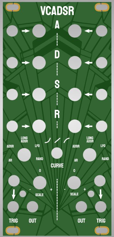
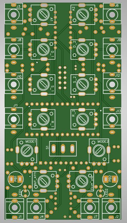
The module has one Panel PCB and one circuit PCB, relatively straight forward, just order with standard settings on jlcpcb or any other pcb site. The build is relatively straight forward, but there is one spot at the top where the IC and pot kind of overlap a bit. be sure to not have stuff standing out too much from the IC so that it contacts the metal housing of the pots and shorts. should be doable
Has been built by multiple people and works fine! I have gotten complaints about small holes for the pushbuttons so I created a V1.1 with bigger holes in the PCB and the panel to allow a wider variety of pushbutton parts.
The code is under the firmware folder and can be uploaded to the nano using the arduino IDE. For the MUX chip it uses the "Analog digital Multiplexers" library found here: source repo , arduino libraries page. You can get it from the library browser inside arduino IDE.
In general, to make it easier on myself I have wired it such that the CV replaces knob values so the knobs are useless if something is plugged in. In my experience this is not that much of a problem as you usually either want to dial in a specific shape or have an lfo etc plugged in. The cool (at least I think it's cool) thing is that you can change CV during a phase to affect the progession of the current phase.
The modules has the following modes:
Curve switch switches between linear, exponential and logarithmic. This is the one thing shared by both channels otherwise they operate independently.
| Qty | Value | Footprint | References |
|---|---|---|---|
| 12 | 100k | easyeda:R09-5KΩ | A1, A2, D_1, D_2, MODE1, MODE2, OUT_ATT1, OUT_ATT2, R_1, R_2, S_1, S_2 |
| 8 | 33k | easyeda:R_AXIAL-0.3 | R9, R14, R18, R20, R23, R24, R27, R28 |
| 8 | 47k | easyeda:R_AXIAL-0.3 | R6, R12, R17, R19, R21, R22, R25, R26 |
| 4 | 1k | easyeda:R_AXIAL-0.3 | R1, R2, R4, R13 |
| 4 | S | easyeda:DO-34_BD1.6-L3.0-P7.00-D0.6-RD | D1, D2, D3, D4 |
| 2 | 100k | easyeda:R_AXIAL-0.3 | R5, R15 |
| 2 | 100n | easyeda:RAD-0.1 | C3, C4 |
| 2 | 10k | easyeda:R_AXIAL-0.3 | R7, R16 |
| 2 | 10u | easyeda:CAP-D4.0×F1.5 | C1, C2 |
| 2 | 200k | easyeda:R_AXIAL-0.3 | R3, R11 |
| 2 | 3k3 | easyeda:R_AXIAL-0.3 | R8, R10 |
| 2 | LED TBR | easyeda:LED-3MM/2.54 | LED1, LED2 |
| 1 | CD74HC4051_THT_DIP-16 | easyeda:CD74HC4051_THT_DIP-16 | U1 |
| 1 | CVA1 | easyeda:THONKICONN_1 | J3 |
| 1 | CVA2 | easyeda:THONKICONN_1 | J6 |
| 1 | CVD1 | easyeda:THONKICONN_1 | J8 |
| 1 | CVD2 | easyeda:THONKICONN_1 | J9 |
| 1 | CVR1 | easyeda:THONKICONN_1 | J11 |
| 1 | CVR2 | easyeda:THONKICONN_1 | J13 |
| 1 | CVS1 | easyeda:THONKICONN_1 | J10 |
| 1 | CVS2 | easyeda:THONKICONN_1 | J12 |
| 1 | MCP4728 | easyeda:HDR-M-2.54_1X10 | J5 |
| 1 | OUT_1 | easyeda:THONKICONN_1 | J4 |
| 1 | OUT_2 | easyeda:THONKICONN_1 | J7 |
| 1 | PWER | easyeda:EURORACK_POWER_V2 | EP1 |
| 1 | SPDT | easyeda:TOGGLE SWITCH SPDT RED 3 PIN ON-OFF-ON 3 SPDT SMALL AC 6A/125V 3A/250V | S1 |
| 1 | TL072 | easyeda:DIP8 | U3 |
| 1 | TRIG1 | easyeda:PUSHBUTTON | PB1 |
| 1 | TRIG1_IN | easyeda:THONKICONN_1 | J1 |
| 1 | TRIG2 | easyeda:PUSHBUTTON | PB2 |
| 1 | TRIG2_IN | easyeda:THONKICONN_1 | J2 |
hearthsinger/profane-geometry
Digitally controlled triangle-core VCO with 4 individual waveshapes, plus one mix output with per-wave attenuation


CrashOverride85/zc95
4 channel EStim box inspired by the mk312bt, with Lua scripting support

thebiguno/microcontroller-projects
A home for a bunch of microcontroller projects which don't warrant their own repos.

DanielMartensson/STM32-Ethernet-Camera
PCB board with camera and ethernet connection + CAN-bus


Testbild-synth/super-sweet-16
Deluxe 16-step knob-per-function sequencer Module for eurorack
It measures 58.4 × 108.7 mm and has 2 copper layers.
69 parts, built around the TL072 and MCP4728-E/UN. The full list of its parts is on this page, with links to each part's symbol and footprint where PCBKit's library has them.
From the Testbild-synth/dual-vcadsr repository on GitHub, at the commit this page was made from: the board is design files/pcb/circuit_pcb.kicad_pcb. PCBKit opens the board in the browser, with nothing to install.
Its repository states no licence, so its author keeps all rights: ask Testbild-synth before reusing the design.