

2 layers140 × 100 mm
Bmsmot
GliderWinchItems/bmsmot
The contactor function measures the high voltage using a STM32L431RCT6, ground isolated and communicates readings to the main processor via uart with opto-isolator.
266 partsCC0-1.0
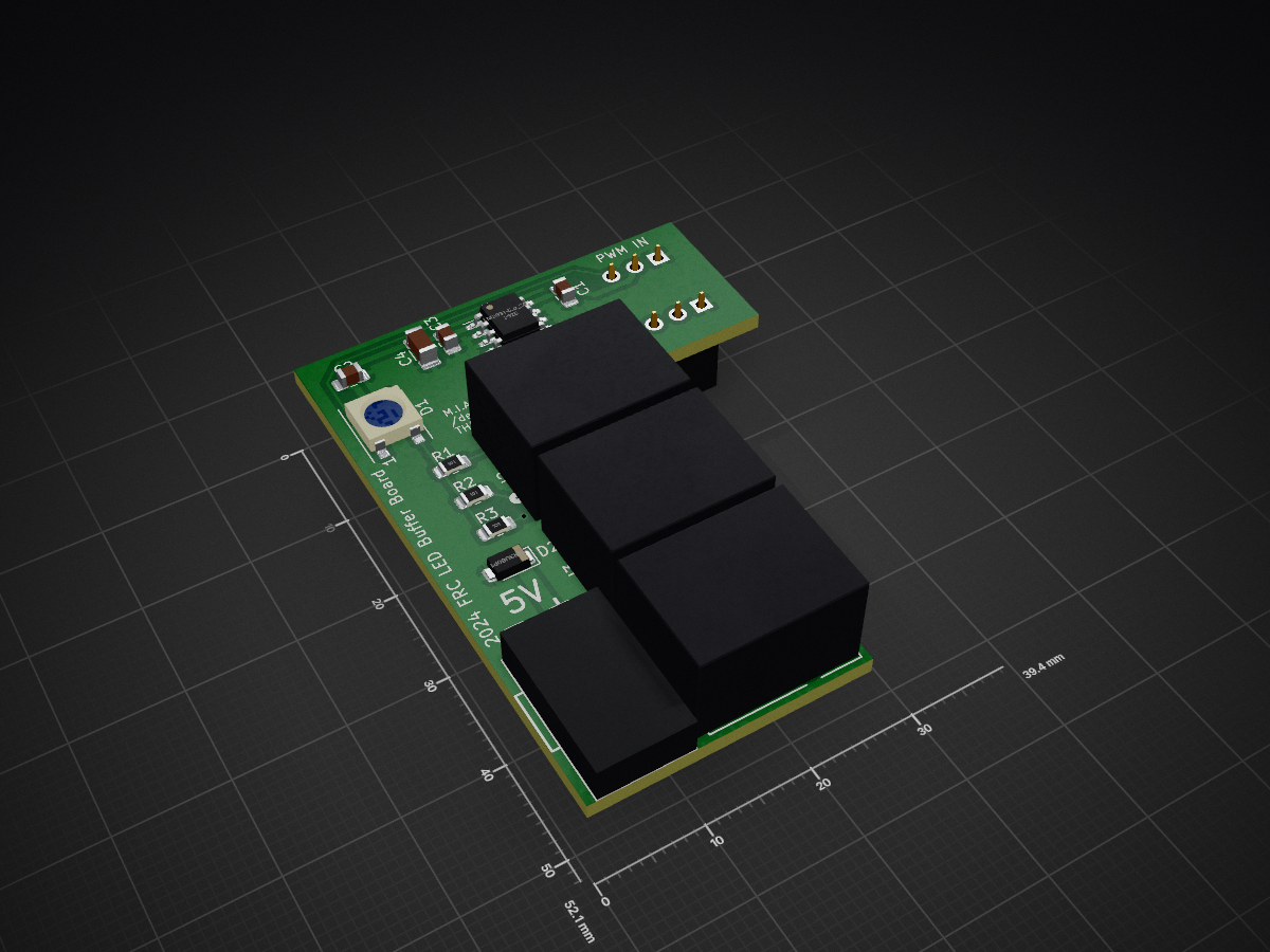
 Team-4795/rio-RGB_LED-buffer-board
a pcb that mounts to a RoboRIO and buffers the data stream for WS2812b and similar LED strips
Ledbuffer is an open-source printed circuit board by Team-4795, from the Team-4795/rio-RGB_LED-buffer-board repository on GitHub, published under the GPL-3.0 licence. It is a 2-layer board of 39.4 × 52.1 mm with 16 parts on 13 nets, routed with 41 tracks and 1 via.
It is built around the SBR3U60P1 and WS2812B. Its parts include 6 connectors, 4 capacitors, 3 resistors, 2 diodes and 1 IC. It belongs with the lEDs and displays boards of this library.
a pcb that mounts to a RoboRIO and buffers the data stream for WS2812b and similar LED strips
The RoboRIO can generate a data stream for addressable "smart" LED strips built from WS2812b and similar LEDs. This data comes out on one of the PWM ports, but is much faster than the typical "servo" PWM data. As such, it is more sensitive to signal integrity issues, especially when splitting it to drive multiple LED strips with identical data.
The tutorial and circuit board here is inspired by a discussion on the Chief Delphi forums https://www.chiefdelphi.com/t/wrong-colors-from-ws2812-led-strips-driven-by-roborio/434199
The basic idea is that we use one WS2812b addressable LED as a "buffer", to recieve the data stream from the RoboRIO, and retransmit it downstream to one or more LED strips on the robot.
This has two benefits:
References
https://docs.wpilib.org/en/stable/docs/software/hardware-apis/misc/addressable-leds.html
https://www.chiefdelphi.com/t/wrong-colors-from-ws2812-led-strips-driven-by-roborio/434199
| Qty | Value | Footprint | References |
|---|---|---|---|
| 3 | 100 | Resistor_SMD:R_0805_2012Metric_Pad1.20x1.40mm_HandSolder | R1, R2, R3 |
| 3 | 1uF | Capacitor_SMD:C_0805_2012Metric_Pad1.18x1.45mm_HandSolder | C1, C2, C3 |
| 3 | Conn_01x03 | Library:CONN_70555-0002_MOL | J2, J3, J4 |
| 2 | Conn_01x03 | Connector_PinSocket_2.54mm:PinSocket_1x03_P2.54mm_Vertical | J1, J6 |
| 1 | 100uF | Capacitor_SMD:C_1206_3216Metric_Pad1.33x1.80mm_HandSolder | C4 |
| 1 | Conn_01x02 | Library:26011102 | J5 |
| 1 | LM2931-5.0_SO8 | Package_SO:SOIC-8_3.9x4.9mm_P1.27mm | U1 |
| 1 | SBR3U60P1 | Diode_SMD:D_PowerDI-123 | D2 |
| 1 | WS2812B | LED_SMD:LED_WS2812B_PLCC4_5.0x5.0mm_P3.2mm | D1 |
GliderWinchItems/bmsmot
The contactor function measures the high voltage using a STM32L431RCT6, ground isolated and communicates readings to the main processor via uart with opto-isolator.

fossasia/pslab-hardware
PSLab Hardware Design and Schematics https://pslab.io

FrameworkComputer/ExpansionCards
Reference designs and documentation to create Expansion Cards for the Framework Laptop


PrintersForAnts/Micron
If you want to purchase full kits there are 3 available (Kits are slowly updating to R1 hardware just make sure to double check the included hardware in your kit and if you have any questions reach out in the discord)


It measures 39.4 × 52.1 mm and has 2 copper layers, 1.6 mm thick.
16 parts, built around the SBR3U60P1 and WS2812B. The full list of its parts is on this page, with links to each part's symbol and footprint where PCBKit's library has them.
From the Team-4795/rio-RGB_LED-buffer-board repository on GitHub, at the commit this page was made from: the board is kicad/ledbuffer.kicad_pcb and its schematic kicad/ledbuffer.kicad_sch. PCBKit opens the board in the browser, with nothing to install.
Its repository publishes it under the GPL-3.0 licence: you may reuse it on that licence's terms (keep the author's notice, and for a copyleft licence share your changes alike).