
2 layers99.1 × 59.7 mm
LaserHarp3 - Rev3.1
amonbenson/laserharp
Setup a virtual environment and install the dependencies:
134 parts1

Designed a Handheld Game Console PCB in KiCad around an STM32F103.
Gameboy is an open-source printed circuit board by TalhaHossainKhan, from the TalhaHossainKhan/Handheld-Game-Console repository on GitHub. It is a 2-layer board of 110.5 × 75.5 mm with 57 parts on 59 nets.
It is built around the STM32F103C8T6, AMS1117-3.3 and 1N4148W, with the AO3401A and BC847 among its other parts. Its parts include 16 capacitors, 11 resistors, 8 switches, 5 connectors and 3 ICs. It belongs with the retro computing and games boards and the STM32 boards of this library.


A battery-powered handheld game console built around an STM32F103C8T6. This repository holds the KiCad hardware design: a 2-layer board with an SPI TFT display, microSD storage, PWM buzzer audio, a six-button game pad, USB-C charging with automatic battery/USB power switching, and an SWD debug header.
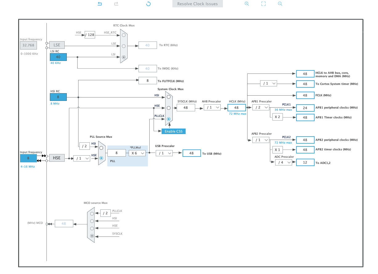
| MCU | STM32F103C8T6, LQFP-48, 16 MHz HSE crystal |
| Display | SPI1 TFT on an 8-pin header (CS / RES / DC / MOSI / SCK + backlight) |
| Storage | microSD over SPI2 on a 4-pin header |
| Audio | PWM buzzer on PB6 (TIM4_CH1) driven through a BC847 low-side switch |
| Controls | 6 tactile buttons (D-pad + A/B), boot-select and power slide switches |
| Power in | USB-C receptacle with 5.1 kΩ CC resistors |
| Charging | MCP73831 single-cell Li-Po charger, ~500 mA, status LED |
| Power path | Schottky (USB) + P-channel MOSFET (battery) auto-switchover |
| Regulation | AMS1117-3.3 LDO → 3.3 V rail, ferrite-filtered VDDA |
| Monitoring | Battery voltage divider into ADC channel PA6 |
| Board | 110.5 × 75.5 mm, 2 layers, 1.6 mm FR4, 6 × M2 mounting holes |
| Debug | 4-pin SWD header (SWDIO / SWCLK / 3.3 V / GND) |
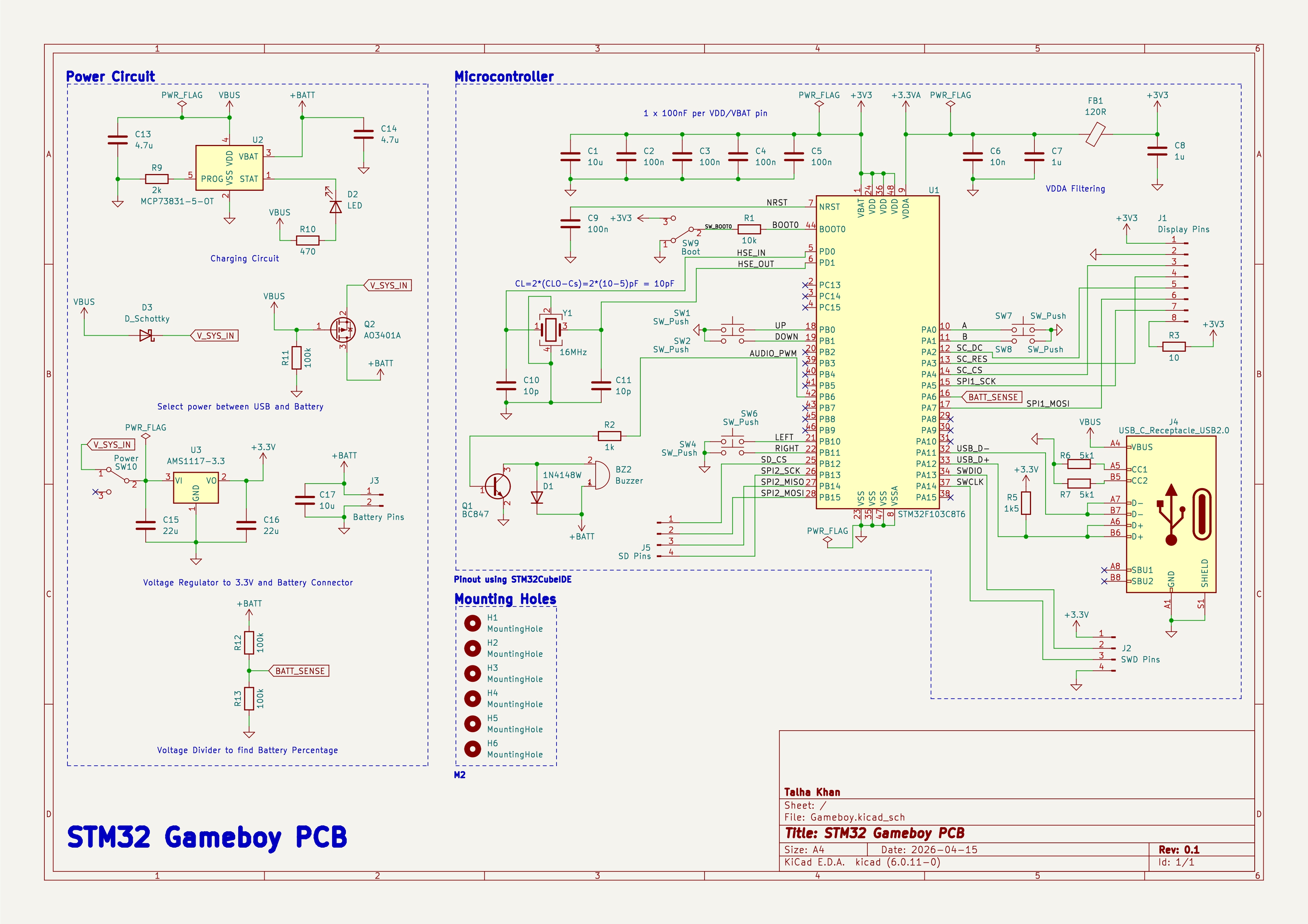
The sheet is split into a power section (charging, power path, regulation and battery sensing) and a microcontroller section (clock, buttons, audio, display, microSD, USB-C and SWD).
Peripherals and the clock tree are configured in STM32CubeIDE.
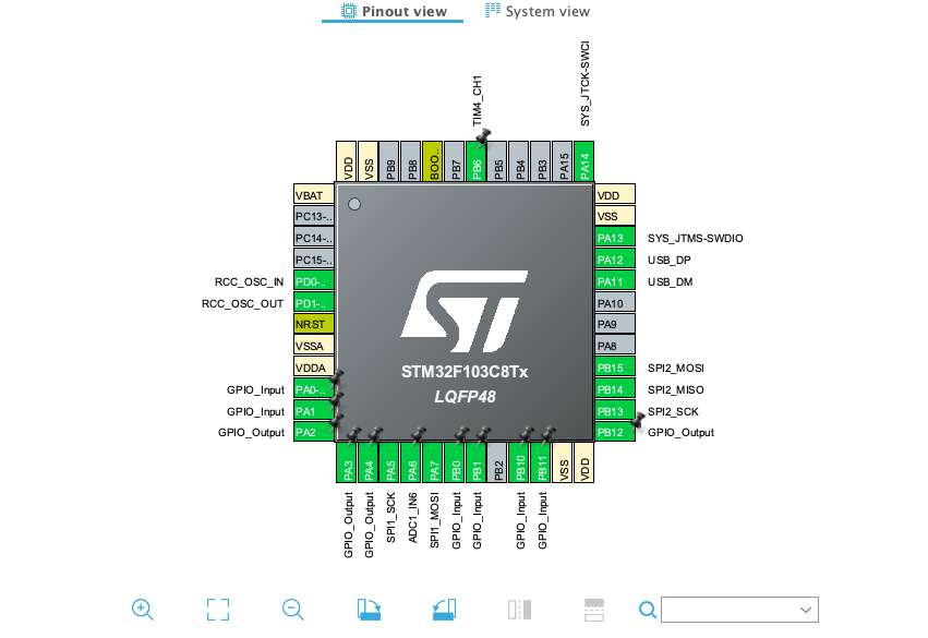
SPI1 drives the display, SPI2 the microSD card, TIM4_CH1 generates the buzzer PWM on PB6, and ADC1_IN6 reads the battery divider on PA6. The D-pad and A/B buttons are plain GPIO inputs, PD0/PD1 carry the external crystal, and PA13/PA14 are reserved for SWD.
USB-C VBUS ─┬─ MCP73831 charger ── +BATT ── JST-PH battery
            │        (R9 = 2k → ~500 mA charge current, status LED)
            │
            ├─ D3 Schottky ─────────┐
            │                       ├─ V_SYS_IN ─ SW10 ─ AMS1117-3.3 ─ +3.3V
+BATT ── Q2 AO3401A P-MOSFET ───────┘
         (gate tied to VBUS, 100k pulldown)
With USB plugged in, VBUS pulls the P-MOSFET gate high and disconnects the battery from the system rail, so the load runs from USB while the charger works on the cell. Unplug USB and the 100 kΩ pulldown turns the MOSFET on, handing the system back to the battery. The Schottky keeps battery current out of VBUS.
The 3.3 V analog supply is filtered from the digital rail through a 120 Ω ferrite bead with 10 nF + 1 µF, and each VDD/VBAT pin gets its own 100 nF capacitor alongside a 10 µF bulk cap.
A 100 kΩ / 100 kΩ divider halves the battery voltage into PA6 (ADC12_IN6), so a full 4.2 V cell reads about 2.1 V — comfortably inside the ADC range.
All six game buttons switch to ground, so the firmware enables the internal
pull-ups. SW9 selects the BOOT0 level through a 10 kΩ resistor for the
bootloader, and SW10 is the main power slide switch ahead of the regulator.
PB6 (TIM4_CH1) drives the base of a BC847 through a 1 kΩ resistor; the buzzer
sits between +BATT and the collector with a 1N4148W flyback diode across it.
Tone generation is therefore a straight PWM/timer job in firmware.
| Function | Signal | Port | Pin |
|---|---|---|---|
| Display chip select | SC_CS | PA4 | 14 |
| Display reset | SC_RES | PA3 | 13 |
| Display data/command | SC_DC | PA2 | 12 |
| Display SPI clock | SPI1_SCK | PA5 | 15 |
| Display SPI data | SPI1_MOSI | PA7 | 17 |
| microSD chip select | SD_CS | PB12 | 25 |
| microSD SPI clock | SPI2_SCK | PB13 | 26 |
| microSD SPI MISO | SPI2_MISO | PB14 | 27 |
| microSD SPI MOSI | SPI2_MOSI | PB15 | 28 |
| D-pad up | UP | PB0 | 18 |
| D-pad down | DOWN | PB1 | 19 |
| D-pad left | LEFT | PB10 | 21 |
| D-pad right | RIGHT | PB11 | 22 |
| Button A | A | PA0 | 10 |
| Button B | B | PA1 | 11 |
| Buzzer PWM | AUDIO_PWM | PB6 | 42 |
| Battery sense | BATT_SENSE | PA6 | 16 |
| USB data − | USB_D- | PA11 | 32 |
| USB data + | USB_D+ | PA12 | 33 |
| SWD data | SWDIO | PA13 | 34 |
| SWD clock | SWCLK | PA14 | 37 |
| Crystal in | HSE_IN | PD0 | 5 |
| Crystal out | HSE_OUT | PD1 | 6 |
| Boot select | BOOT0 | — | 44 |
| Reset | NRST | — | 7 |
The USB D+ line carries the 1.5 kΩ pull-up to 3.3 V required for full-speed device enumeration. The display backlight pin is tied to 3.3 V through a 10 Ω series resistor.
J1 — display (1×8, 2.54 mm)
| 1 | 2 | 3 | 4 | 5 | 6 | 7 | 8 |
|---|---|---|---|---|---|---|---|
| +3V3 | GND | CS | RES | DC | MOSI | SCK | Backlight |
J5 — microSD (1×4, 2.54 mm)
| 1 | 2 | 3 | 4 |
|---|---|---|---|
| CS | MOSI | MISO | SCK |
J2 — SWD (1×4, 2.54 mm)
| 1 | 2 | 3 | 4 |
|---|---|---|---|
| +3.3V | SWDIO | SWCLK | GND |
57 placements, all SMD except the headers, switches and buzzer.
| Qty | References | Value | Footprint |
|---|---|---|---|
| 1 | U1 | STM32F103C8T6 | LQFP-48 7×7 mm |
| 1 | U2 | MCP73831-5-OT | SOT-23-5 |
| 1 | U3 | AMS1117-3.3 | SOT-223-3 |
| 1 | Y1 | 16 MHz crystal | 3.2 × 2.5 mm, 4-pin |
| 1 | Q1 | BC847 NPN | SOT-23 |
| 1 | Q2 | AO3401A P-MOSFET | SOT-23 |
| 1 | D1 | 1N4148W | SOD-123 |
| 1 | D2 | LED (charge status) | 0603 |
| 1 | D3 | Schottky | SMA |
| 1 | FB1 | 120 Ω ferrite bead | 0603 |
| 1 | BZ2 | Magnetic buzzer | PKLCS1212E |
| 2 | C1, C17 | 10 µF | 0603 |
| 5 | C2–C5, C9 | 100 nF | 0402 |
| 1 | C6 | 10 nF | 0402 |
| 2 | C7, C8 | 1 µF | 0402 |
| 2 | C10, C11 | 10 pF | 0402 |
| 2 | C13, C14 | 4.7 µF | 0603 |
| 2 | C15, C16 | 22 µF | 0805 |
| 1 | R1 | 10 kΩ | 0402 |
| 1 | R2 | 1 kΩ | 0402 |
| 1 | R3 | 10 Ω | 0402 |
| 1 | R5 | 1.5 kΩ | 0402 |
| 2 | R6, R7 | 5.1 kΩ | 0402 |
| 1 | R9 | 2 kΩ | 0402 |
| 1 | R10 | 470 Ω | 0402 |
| 3 | R11–R13 | 100 kΩ | 0603 |
| 6 | SW1, SW2, SW4, SW6–SW8 | Tactile push button | SKQG |
| 2 | SW9, SW10 | SPDT slide switch | PCM12 |
| 1 | J1 | Display header 1×8 | 2.54 mm |
| 1 | J2 | SWD header 1×4 | 2.54 mm |
| 1 | J3 | Battery connector | JST-PH 2-pin |
| 1 | J4 | USB-C receptacle | GCT USB4105, 16P |
| 1 | J5 | microSD header 1×4 | 2.54 mm |
| 6 | H1–H6 | Mounting hole | M2, 2.2 mm |
Gameboy.kicad_pro     KiCad project
Gameboy.kicad_sch     Schematic (single sheet)
Gameboy.kicad_pcb     Board layout
MyParts.pretty/       Custom footprint library
docs/ Schematic print and STM32CubeIDE configuration imagesInstall KiCad 6.0 or newer, then open
Gameboy.kicad_pro. Newer KiCad versions will offer to upgrade the file format;
the custom footprint library MyParts.pretty is referenced from the project and
needs no extra setup.
Talha Khan
| Qty | Value | Footprint | References |
|---|---|---|---|
| 6 | MountingHole | MountingHole:MountingHole_2.2mm_M2 | H1, H2, H3, H4, H5, H6 |
| 6 | SW_Push | Button_Switch_SMD:SW_SPST_SKQG_WithoutStem | SW1, SW2, SW4, SW6, SW7, SW8 |
| 5 | 100n | Capacitor_SMD:C_0402_1005Metric | C2, C3, C4, C5, C9 |
| 3 | 100k | Resistor_SMD:R_0603_1608Metric | R11, R12, R13 |
| 2 | 10p | Capacitor_SMD:C_0402_1005Metric | C10, C11 |
| 2 | 10u | Capacitor_SMD:C_0603_1608Metric | C1, C17 |
| 2 | 1u | Capacitor_SMD:C_0402_1005Metric | C7, C8 |
| 2 | 22u | Capacitor_SMD:C_0805_2012Metric | C15, C16 |
| 2 | 4.7u | Capacitor_SMD:C_0603_1608Metric | C13, C14 |
| 2 | 5k1 | Resistor_SMD:R_0402_1005Metric | R6, R7 |
| 1 | 10 | Resistor_SMD:R_0402_1005Metric | R3 |
| 1 | 10k | Resistor_SMD:R_0402_1005Metric | R1 |
| 1 | 10n | Capacitor_SMD:C_0402_1005Metric | C6 |
| 1 | 120R | Inductor_SMD:L_0603_1608Metric | FB1 |
| 1 | 16MHz | Crystal:Crystal_SMD_3225-4Pin_3.2x2.5mm | Y1 |
| 1 | 1N4148W | Diode_SMD:D_SOD-123 | D1 |
| 1 | 1k | Resistor_SMD:R_0402_1005Metric | R2 |
| 1 | 1k5 | Resistor_SMD:R_0402_1005Metric | R5 |
| 1 | 2k | Resistor_SMD:R_0402_1005Metric | R9 |
| 1 | 470 | Resistor_SMD:R_0402_1005Metric | R10 |
| 1 | AMS1117-3.3 | Package_TO_SOT_SMD:SOT-223-3_TabPin2 | U3 |
| 1 | AO3401A | Package_TO_SOT_SMD:SOT-23 | Q2 |
| 1 | BC847 | Package_TO_SOT_SMD:SOT-23 | Q1 |
| 1 | Battery Pins | Connector_JST:JST_PH_S2B-PH-K_1x02_P2.00mm_Horizontal | J3 |
| 1 | Boot | Button_Switch_SMD:SW_SPDT_PCM12 | SW9 |
| 1 | Buzzer | Buzzer_Beeper:Buzzer_Murata_PKLCS1212E | BZ2 |
| 1 | D_Schottky | Diode_SMD:D_SMA | D3 |
| 1 | Display Pins | Connector_PinHeader_2.54mm:PinHeader_1x08_P2.54mm_Vertical | J1 |
| 1 | LED | LED_SMD:LED_0603_1608Metric | D2 |
| 1 | MCP73831-5-OT | Package_TO_SOT_SMD:SOT-23-5 | U2 |
| 1 | Power | Button_Switch_SMD:SW_SPDT_PCM12 | SW10 |
| 1 | SD Pins | Connector_PinHeader_2.54mm:PinHeader_1x04_P2.54mm_Vertical | J5 |
| 1 | STM32F103C8T6 | Package_QFP:LQFP-48_7x7mm_P0.5mm | U1 |
| 1 | SWD Pins | Connector_PinHeader_2.54mm:PinHeader_1x04_P2.54mm_Vertical | J2 |
| 1 | USB_C_Receptacle_USB2.0 | Connector_USB:USB_C_Receptacle_GCT_USB4105-xx-A_16P_TopMnt_Horizontal | J4 |
amonbenson/laserharp
Setup a virtual environment and install the dependencies:


mirmisbahali/macro_keyboard
A custom 6-key macro keyboard built from scratch custom written bare-metal STM32 firmware, hand-drawn schematics, and a PCB designed in KiCAD. No Arduino. No HAL. Just registers, datasheets, and stubbornness.

Tomas-Kuchta-FPV/Open-ESPilot
An open-source project to develop a custom ESP32-based flight controller designed primarily for use with ArduPilot. Focused on affordability, flexibility, and ease of integration with various robotic and UAV platforms.

KIIT-Robotic-Society/Dharma_RoboFest4.0
Dharma Bot is a quadruped robotic dog featuring 12-DOF locomotion, real-time sensing, and a modular subsystem design.

MAWoodMain/ESP-Reflow-Oven
A retro fit of a Lidl middle aisle mini oven into a home reflow oven

It measures 110.5 × 75.5 mm and has 2 copper layers, 1.6 mm thick.
57 parts, built around the STM32F103C8T6, AMS1117-3.3, 1N4148W and AO3401A. The full list of its parts is on this page, with links to each part's symbol and footprint where PCBKit's library has them.
From the TalhaHossainKhan/Handheld-Game-Console repository on GitHub, at the commit this page was made from: the board is Gameboy.kicad_pcb and its schematic Gameboy.kicad_sch. PCBKit opens the board in the browser, with nothing to install.
Its repository states no licence, so its author keeps all rights: ask TalhaHossainKhan before reusing the design.