2 layers110.5 × 75.5 mm
Gameboy
TalhaHossainKhan/Handheld-Game-Console
Designed a Handheld Game Console PCB in KiCad around an STM32F103.
57 parts

 mirmisbahali/macro_keyboard
A custom 6-key macro keyboard built from scratch custom written bare-metal STM32 firmware, hand-drawn schematics, and a PCB designed in KiCAD. No Arduino. No HAL. Just registers, datasheets, and stubbornness.
Stm32 macro keyboard is an open-source printed circuit board by mirmisbahali, from the mirmisbahali/macro_keyboard repository on GitHub. It is a 2-layer board of 50.5 × 74.3 mm with 44 parts on 56 nets.
It is built around the STM32F103C8T6, AMS1117-3.3 and 1N4148W. Its parts include 13 capacitors, 7 diodes, 7 switches, 5 resistors and 4 connectors. It belongs with the keyboards and input boards and the STM32 boards of this library.


A custom 6-key macro keyboard built from scratch custom written bare-metal STM32 firmware, hand-drawn schematics, and a PCB designed in KiCAD. No Arduino. No HAL. Just registers, datasheets, and stubbornness.
Status: Hardware design in progress
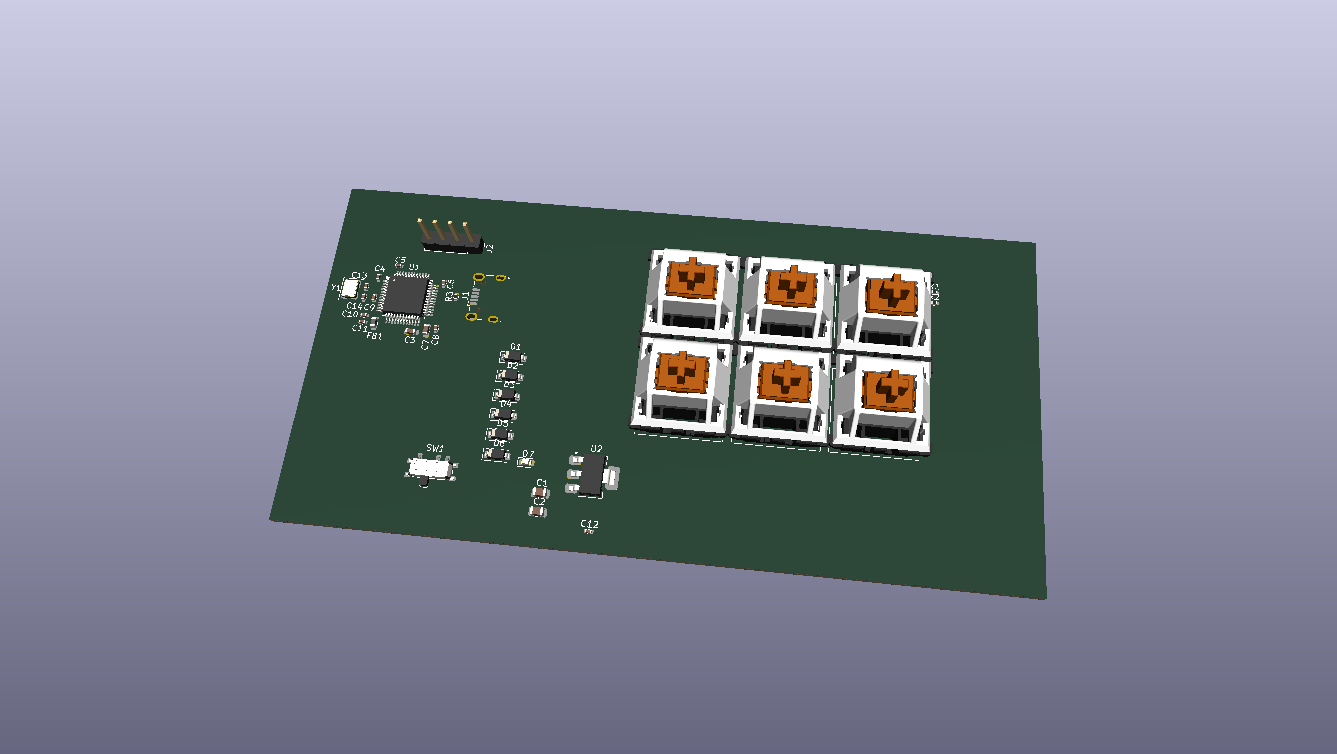
PCB layout and routing in progress.
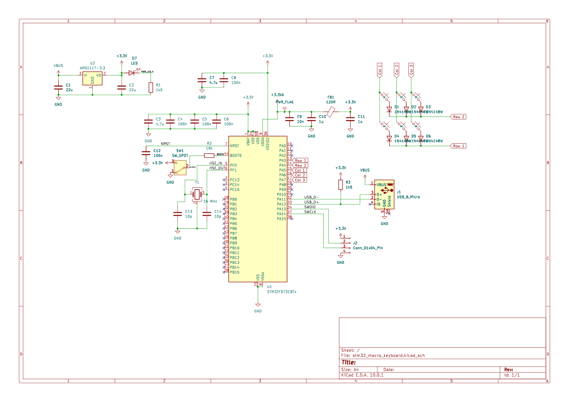
Wiring is completed — schematic still needs to be made neat and tidy.
I am learning to design STM32-based hardware - from choosing a microcontroller and designing the PCB, to writing drivers from scratch in register-level C.
| Item | Detail |
|---|---|
| MCU | STM32F072CBTx — Cortex-M0, 48 MHz, 128 KB flash, LQFP-48 |
| Key matrix | 6 switches with diode-per-key (1N4148W) |
| Power | 3.3 V core, ferrite bead on analog rail (VDDA), decoupling on all supply pins |
| Programming | USB DFU via BOOT0 SPDT switch — no debug probe needed |
| EDA tool | KiCAD 10.0 |
Requirements follow the systems engineering convention: shall = mandatory, should = desired.
| ID | Requirement |
|---|---|
| SYS-01 | The device shall enumerate as a USB HID keyboard on any host OS without requiring driver installation. |
| SYS-02 | The device shall be powered entirely from the USB bus (5 V, ≤ 100 mA). |
| SYS-03 | The device shall support a minimum of 6 independently programmable macro keys. |
| SYS-04 | The device firmware shall be updatable via USB without a hardware debug probe. |
| SYS-05 | All firmware shall be written in register-level C with no vendor HAL or Arduino abstractions. |
| ID | Requirement |
|---|---|
| HW-01 | The MCU core supply (VDD) shall be 3.3 V ± 5%. |
| HW-02 | Each VDD, VDDA, VBAT, and VSSIO2 supply pin shall have a dedicated decoupling capacitor placed within 2 mm of the pin. |
| HW-03 | VDDA shall be filtered from VDD using a ferrite bead to reduce digital noise on the analog supply. |
| HW-04 | Each key switch shall have a dedicated series diode to prevent ghosting in the key matrix. |
| HW-05 | The BOOT0 pin shall be switchable between VDD and GND via an SPDT switch to allow toggling between DFU programming mode and normal run mode. |
| HW-06 | The PCB shall pass KiCAD DRC with zero errors before submission for fabrication. |
| ID | Requirement |
|---|---|
| FW-01 | The firmware shall configure the system clock to 48 MHz using the internal PLL before any peripheral initialisation. |
| FW-02 | The key scan loop shall debounce each key with a settling time of ≤ 5 ms. |
| FW-03 | The firmware shall report a key press to the USB host within 10 ms of a physical key actuation. |
| FW-04 | Macro key mappings shall be stored in non-volatile flash and survive a power cycle. |
| FW-05 | The firmware shall implement the USB HID boot-protocol keyboard descriptor to ensure compatibility with BIOS/UEFI environments. |
| ID | Requirement | Method |
|---|---|---|
| VER-01 | All supply rails measure within tolerance at board bring-up. | Test — multimeter |
| VER-02 | Device enumerates as HID keyboard on Windows, macOS, and Linux. | Test — plug in, check device manager |
| VER-03 | Every key registers a unique, correct HID keycode. | Test — key tester utility |
| VER-04 | Firmware can be flashed via DFU using only the BOOT0 switch and a USB cable. | Demonstration |
| VER-05 | Key mappings persist across power cycles. | Test — assign macro, power cycle, verify |
| VER-06 | PCB DRC passes with zero errors. | Analysis — KiCAD DRC report |
| Qty | Value | Footprint | References |
|---|---|---|---|
| 6 | 1N4148W | Diode_SMD:D_SOD-123 | D1, D2, D3, D4, D5, D6 |
| 6 | ~ | ScottoKeebs_MX:MX_PCB_2.50u | S1, S2, S3, S4, S5, S6 |
| 5 | 100n | Capacitor_SMD:C_0402_1005Metric | C4, C5, C6, C7, C11 |
| 4 | 1k5 | Resistor_SMD:R_0402_1005Metric | R1, R3, R4, R5 |
| 4 | MountingHole | MountingHole:MountingHole_2.2mm_M2 | H1, H2, H3, H4 |
| 3 | Conn_01x04_Pin | Connector_PinHeader_2.54mm:PinHeader_1x04_P2.54mm_Vertical | J2, J3, J4 |
| 2 | 10p | Capacitor_SMD:C_0402_1005Metric | C12, C13 |
| 2 | 1u | Capacitor_SMD:C_0402_1005Metric | C9, C10 |
| 2 | 22u | Capacitor_SMD:C_0805_2012Metric | C1, C2 |
| 1 | 10k | Resistor_SMD:R_0402_1005Metric | R2 |
| 1 | 10n | Capacitor_SMD:C_0402_1005Metric | C8 |
| 1 | 10u | Capacitor_SMD:C_0603_1608Metric | C3 |
| 1 | 120R | Inductor_SMD:L_0603_1608Metric | FB1 |
| 1 | 16MHz | Crystal:Crystal_SMD_3225-4Pin_3.2x2.5mm | Y1 |
| 1 | AMS1117-3.3 | Package_TO_SOT_SMD:SOT-223-3_TabPin2 | U2 |
| 1 | RED | LED_SMD:LED_0603_1608Metric | D7 |
| 1 | STM32F103C8T6 | Package_QFP:LQFP-48_7x7mm_P0.5mm | U1 |
| 1 | SW_SPDT | Button_Switch_SMD:SW_SPDT_PCM12 | SW1 |
| 1 | USB_B_Micro | Connector_USB:USB_Micro-B_Wuerth_629105150521 | J1 |
TalhaHossainKhan/Handheld-Game-Console
Designed a Handheld Game Console PCB in KiCad around an STM32F103.

sean618/MakerTiles
Modular STM32 electronic-tile system: hardware, firmware, the MicroBus + Field Protocol stack, and a Python daemon.

stevel1212-droid/stm32-rtc-climate-controller
Kicad project of an STM32-based board climate controller utilizing an RTC module for time-scheduled environmental reading of temperature/humidity with SHT30 sensor and optional small relay for control.

hardenedlinux/cheap-pcb
Cheap PCB: Better understanding the current status of hardware supply chain

milar111/HEAT
An open-source STM32 SMD assembly station for precision soldering. Uses a custom Smart Pulse & Coast algorithm to drive 400W mains heaters via SSR. Features OLED UI, NTC feedback, and safety cooling.


minhle4397/Line-Follower-Robot-v2
Improved Hardware and Firmware for Line Follower Robot

mupfdev/TrackMAG
An open hardware development board primarily intended for the development of accessible input devices.
It measures 50.5 × 74.3 mm and has 2 copper layers, 1.6 mm thick.
44 parts, built around the STM32F103C8T6, AMS1117-3.3 and 1N4148W. The full list of its parts is on this page, with links to each part's symbol and footprint where PCBKit's library has them.
From the mirmisbahali/macro_keyboard repository on GitHub, at the commit this page was made from: the board is Electronics/stm32_macro_keyboard/stm32_macro_keyboard.kicad_pcb and its schematic Electronics/stm32_macro_keyboard/stm32_macro_keyboard.kicad_sch. PCBKit opens the board in the browser, with nothing to install.
Its repository states no licence, so its author keeps all rights: ask mirmisbahali before reusing the design.