2 layers77.3 × 83.7 mm

 MAWoodMain/ESP-Reflow-Oven2
A retro fit of a Lidl middle aisle mini oven into a home reflow oven
Mini Oven Controller is an open-source printed circuit board by MAWoodMain, from the MAWoodMain/ESP-Reflow-Oven repository on GitHub, published under the MIT licence. It is a 2-layer board of 126 × 57 mm with 46 parts on 57 nets, routed with 234 tracks and 30 vias.
It is built around the ESP32-WROOM-32U, IRM-05-5 and MAX31855KASA+T, with the CX240D5, AMS1117-3.3 and AO3401A among its other parts. Its parts include 13 resistors, 10 connectors, 7 capacitors, 7 ICs and 6 transistors. It belongs with the ESP32 boards of this library.


A retro fit of a Lidl middle aisle mini oven into a home reflow oven
This project came about on a friday night trip to lidl in the UKs second lockdown. I spotted that lidl were selling mini ovens in the middle aisle for a meagre £25 (~$35), having seen many online creators doing their own homemade reflow ovens based on similar toaster ovens I though it would be a worthy weekend project.
Naturally after getting home from lidl and putting away all the chilled and frozen foods I went straight into a teardown to see how this thing was put together, the original oven had 3 dials on the front:
Under the hood there was practically nothing just a large void in the case with a few wires going to the elements, the temperature control was a simple bimetallic strip temeperature control which seems to operate based on the temperature in the chamber next to the oven? Not sure how that could even work properly, either way its going into the bin. Similar story for the mode switch, it just switches in and out elements based on the selection, this will not be required either.
After they were removed I was left with the mains input going through a thermal fuse and into a timer switch, I will keep the timer switch to I can set an automatic off when using the unit under computer control. Also this timer switch makes a rather satisfying ding sound when it turns off, I would hate to lose such an important feature...
Had only a few key objectives when I started this project:
All the mechanical components should be 3D printable using FDM technology.
I wanted to utilise ESPHome as I have been following some creators project using it, and I was keen to give it a go.
I wanted the SMT components on the PCB to be assembled by JLC assembly, I know this one sounds a bit weird given I am constructing a reflow oven, but it honestly is often cheaper to have components assembled at JLCPCB rather than ordering them, paying shipping for both PCBs and components then organising paste and a stencil. This oven if for when I have to use components not available for this service and for special cases.
I needed the oven to follow a simple reflow curve, doesn't need to be prefect but it must work for basic board with normal components.
I also wanted to try out a Nextion display as I had also seen a few videos by Vaclav Chaloupka making some cool home assistant home control panels using the modules.
Finally I wanted to keep all the original products safety features in place so I don't create a major fire hazard.
I knew this project would involve working with mains electricity so I made sure to choose components with recognisable approvals and safety certifications for the mains side of the electronics. For that reason I chose a meanwell isolated AC to DC converter to power the low voltage side of the electronics.
The heating elements were tested and found to draw around 600 Watts each which in the UK is around 2.5-3 Amps, the switching component selected for this load was a 5 Amp solid state relay. Specifically I made sure to select a zero crossing SSR as with resistive loads it is better for the powerline quality in the house as it avoids harsh mid phase loading. A CX240D5 was used as it was easily available and has approvals several reputable approvals (UL, CSA and CE).
A supplementary on board fuse holder and fuse was included in the design just in case the plug fuse is especially slow or overrated.
The low voltage side will be an ESP32, some thermocouple inputs and a DC output to allow for a fan in the future if required to cool the electronics.
For the thermocouple inputs I have very few ICs to choose from as JLC Assembly did not seem to have many available, I settled on the MAX31855 which includes cold junction compensation and requires no external components to work aside from basic decoupling. It uses SPI to send data back to the MCU, it has no settings to configure and does not support receiving data over SPI.
The fan output is a 5V power output which consists of a P-Channel MOSFET and a NPN drive transistor for the gate. This output can only support about 0.5A output as the meanwell power supply is only rated for 1A and the ESP32 required 0.5A.
Below is the 3D model of the PCB in the Kicad 3D viewer:

In addition to the assembled PCB discussed above and the 3D printed parts, a few extra components are required:
The PCBs arrived SMT complete from JLCPCB, the THT components were hand soldered in to finish the PCBA off. At this point it is worth getting the firmware uploaded into the ESP32, after the first firmware is loaded OTA updating is trivial using the ESPHome home assistant plugin.
It is also worth preparing the Nextion display module, I uploaded the firmware to the display using a USB to UART module and the nextion editor software.
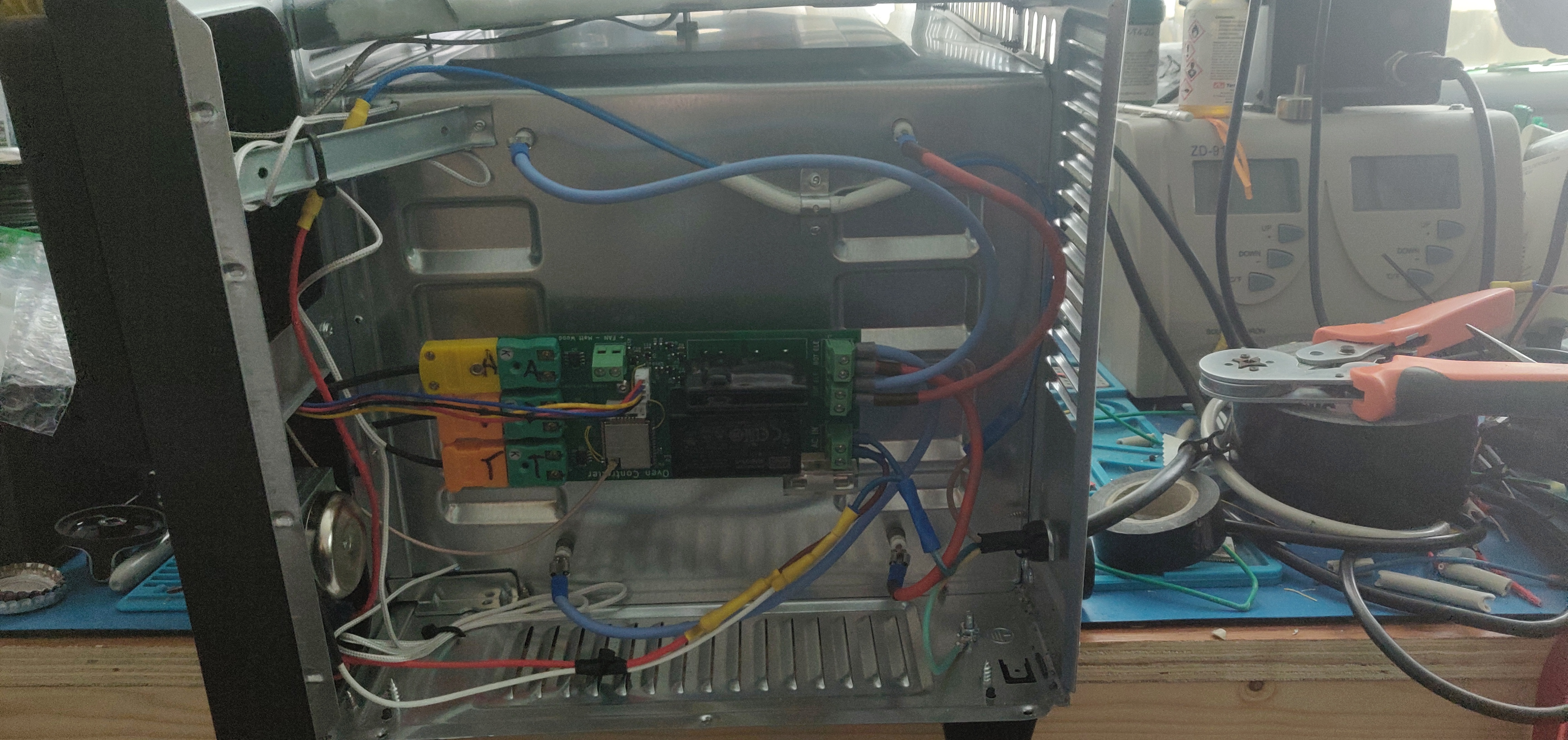
As discussed in the project intro the original mode and temperature knobs were removed. Next some stand offs were mounted in the space next to the heating chamber to affix the PCB to. The PCB was mounted and custom cables were crimped to connect up the mains input and heating elements. Some holes were drilled to allow the thermocouples into the heated chamber one on the top of the right side and one on the bottom.
A hole was drilled for the SMA connector on the top and the u.FL end was plugged into the ESP32 module.
Next the 3D printed LCD mount was screwed into the front panel using the original self tapping screws which held the old controls on. The LCD was itself screwed into the mount using M3x10mm pan head bolts and the cable was run back to the main PCB. The LCD cover was pressed on to finish off the front. I discovered you must take care pressing this cover on as if you press it on too far it triggers the resistive touch screen on the nextion module.
Below is a photo of the electronics compartment, please don't judge the wire runs too heavily as it has been improved since.
Once the assembly was complete the PIDs loops require tuning so I attached the top and bottom thermocouples to a blank PCB and ran the auto tune routine for both the top and bottom PID control loops. These values were saved into the ESPHome YAML so they persist though reboot.
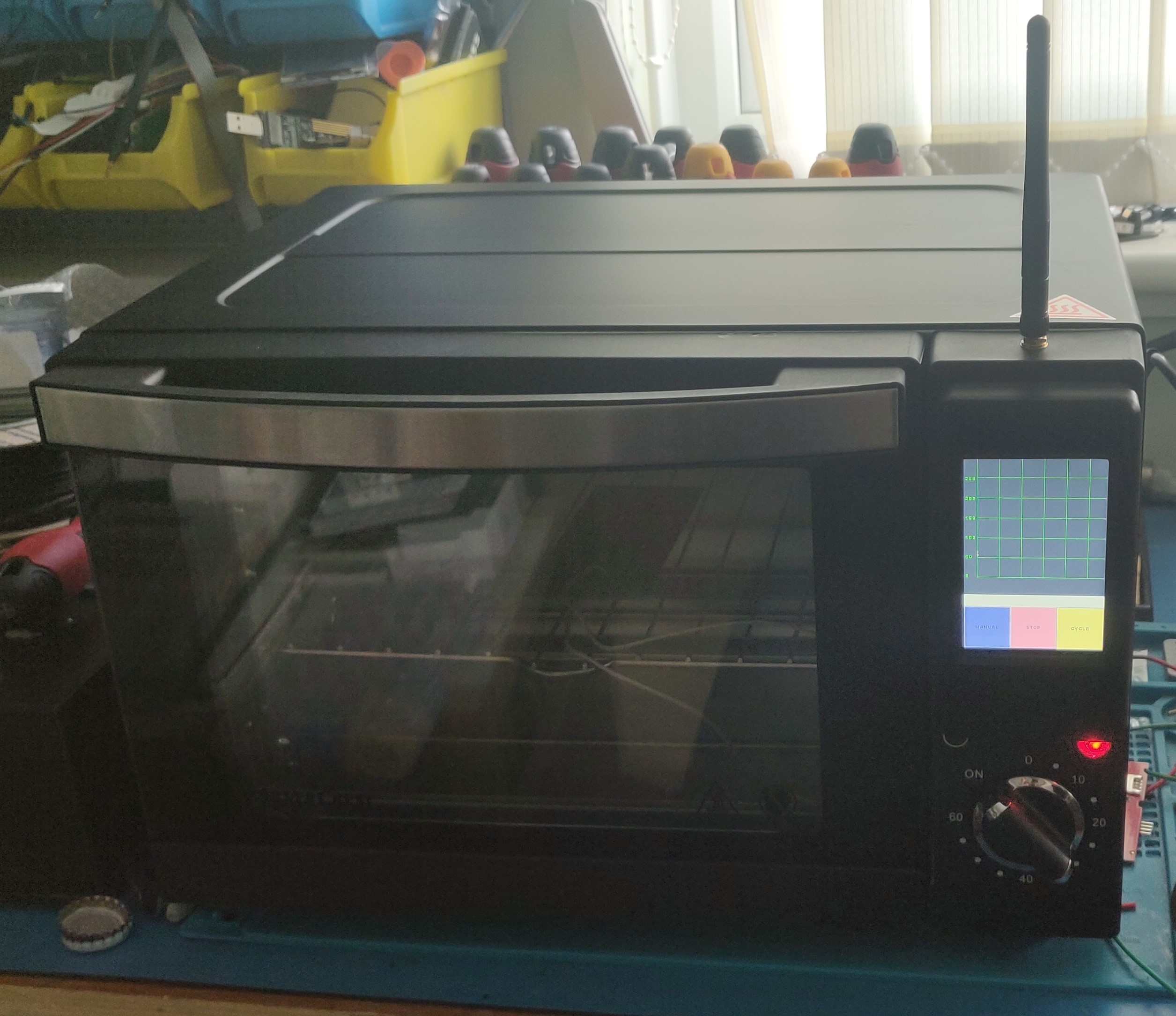
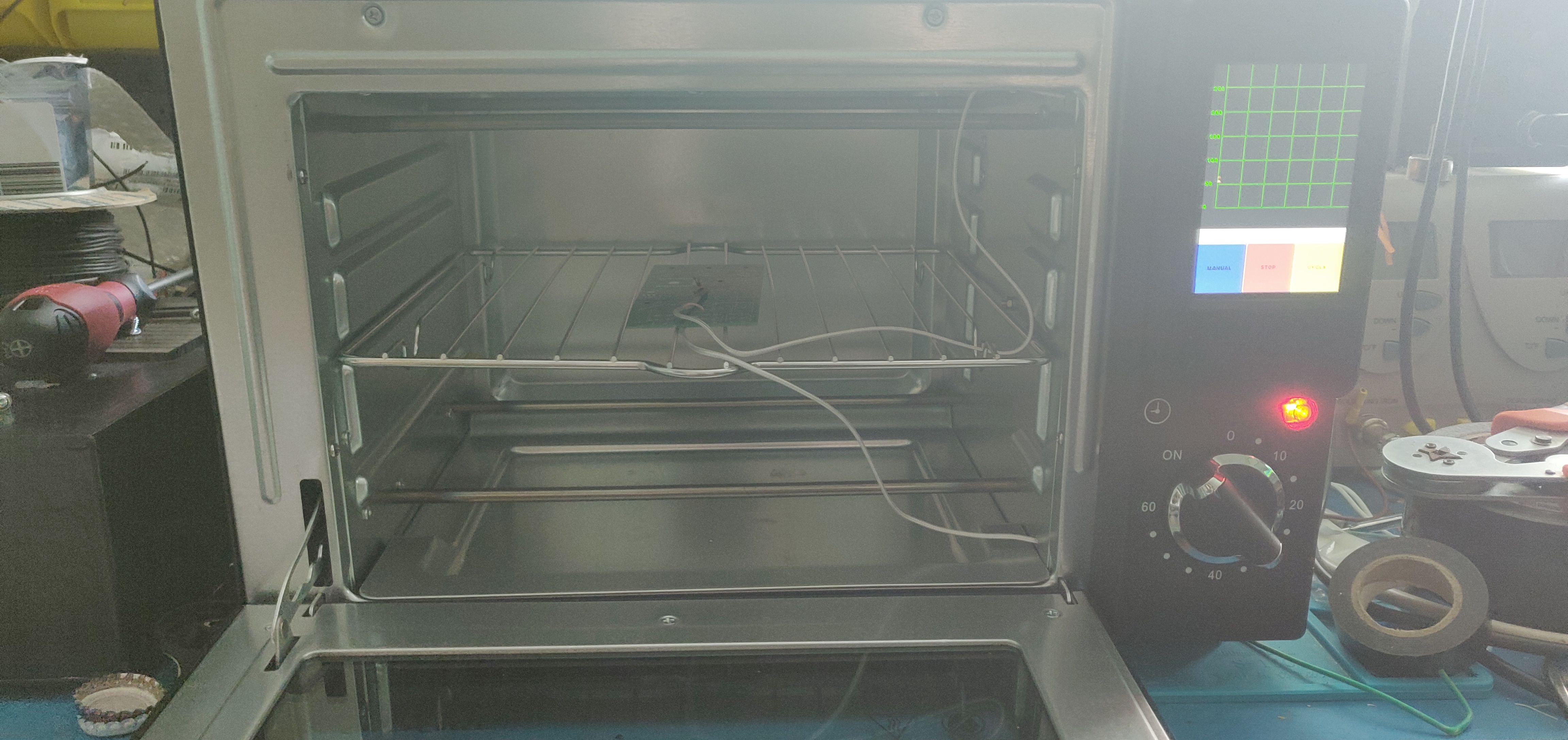
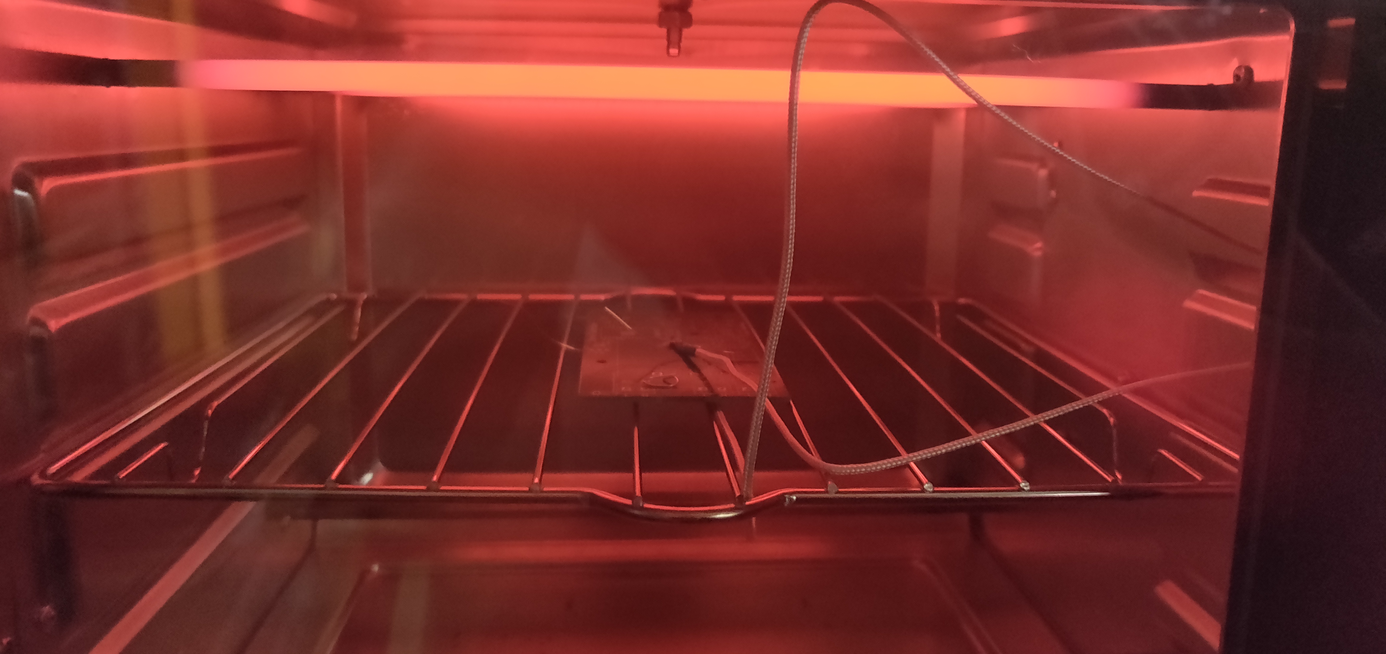
I am happy with the final product I think the outside looks very clean and the interface is simple and intuitive. There are a few issues I ran into during this project:
Two PID loops, since I went with independent top and bottom heat controls I have two PID loops for the top and bottom systems but since these two systems are used simultaneously they are not independent closed loop systems. The issue with this is that the PID settings do not account properly the other loop existing and thus tend to overshoot the set temperature when they are used together. For reflow I have not found a 5 degree overshoot to be a problem but for some use cases I could see it being an issue. I would propose two possible solutions: You could either combine the two elements and control them as a single large element in a single PID loop or you could use a more sophisticated control system which accounted for the second elements influence.
Dependence on Home assistant, in the way I am currently controlling it the oven relys on HASS to orchastrate the reflow cycle, if the connection to HASS is lost the oven could be left on at the set temperature for too long. Also it means if HASS is unavailable the cycle button does not work properly. This could be resolved by hard coding the cycle into the ESPHome config, but I have not done this yet.
Cost, this project was started because of the cheapness of the oven but untimately its cost mostly came in the PCBA price. The total price of the PCB was around £17 for the PCBs from JLC (part assembled) and around £35 of THT parts from Farnell for a total cost of £52 (parts) + £25 (oven) = £77 (~$105). I don't feel I over spent given the capability of this oven but it is slightly more then I though it would cost. The main cost issue was in the farnell parts but this was caused by the safe main voltage components, so it is likely unavoidable.
Distributed under the MIT License. See LICENSE for more information.
| Qty | Value | Footprint | References |
|---|---|---|---|
| 10 | 10K | Resistor_SMD:R_0603_1608Metric | R1, R2, R3, R4, R5, R6, R9, R11, R12, R13 |
| 5 | 100nF | Capacitor_SMD:C_0603_1608Metric | C3, C4, C5, C6, C7 |
| 3 | 1K | Resistor_SMD:R_0603_1608Metric | R7, R8, R10 |
| 3 | AO3401A | Package_TO_SOT_SMD:SOT-23 | Q1, Q2, Q6 |
| 3 | BC847 | Package_TO_SOT_SMD:SOT-23 | Q3, Q4, Q5 |
| 3 | MAX31855KASA | Package_SO:SOIC-8_3.9x4.9mm_P1.27mm | U5, U6, U7 |
| 3 | Thermocouple | SnapEda:IM-K-PCB | J5, J6, J7 |
| 2 | 10uF | Capacitor_SMD:C_0805_2012Metric | C1, C2 |
| 2 | CX240D5 | SnapEda:CRYDOM_CX240D5 | U1, U2 |
| 2 | MountingHole | MountingHole:MountingHole_3.2mm_M3 | H1, H2 |
| 1 | 696101000002 | SnapEda:696101000002 | J4 |
| 1 | AC IN | TerminalBlock_Phoenix:TerminalBlock_Phoenix_MKDS-3-2-5.08_1x02_P5.08mm_Horizontal | J1 |
| 1 | AMS1117-3.3 | Package_TO_SOT_SMD:SOT-223-3_TabPin2 | U3 |
| 1 | Bottom Element | TerminalBlock_Phoenix:TerminalBlock_Phoenix_MKDS-3-2-5.08_1x02_P5.08mm_Horizontal | J3 |
| 1 | Conn_01x04_Male | Connector_JST:JST_PH_B4B-PH-K_1x04_P2.00mm_Vertical | J9 |
| 1 | Conn_01x06_Male | Connector_JST:JST_PH_B6B-PH-K_1x06_P2.00mm_Vertical | J8 |
| 1 | ESP32-WROOM-32U | RF_Module:ESP32-WROOM-32U | U4 |
| 1 | Fan | TerminalBlock_Phoenix:TerminalBlock_Phoenix_MKDS-3-2-5.08_1x02_P5.08mm_Horizontal | J10 |
| 1 | IRM-05-5 | Converter_ACDC:Converter_ACDC_MeanWell_IRM-05-xx_THT | PS1 |
| 1 | Top Element | TerminalBlock_Phoenix:TerminalBlock_Phoenix_MKDS-3-2-5.08_1x02_P5.08mm_Horizontal | J2 |


C3MA/MrReflow
To achieve that, readings from a thermocouple are used for closed loop temperature control of the target board. The controller does it's best to follow a preconfigured temperature profile for a particular SMT soldering.

freezweb/de.freezweb.heizungssteuerung
Dieses Verzeichnis enthaelt den KiCad-Startentwurf fuer die dezentrale Pumpengruppen-Platine:

Tomas-Kuchta-FPV/Open-ESPilot
An open-source project to develop a custom ESP32-based flight controller designed primarily for use with ArduPilot. Focused on affordability, flexibility, and ease of integration with various robotic and UAV platforms.

KIIT-Robotic-Society/Dharma_RoboFest4.0
Dharma Bot is a quadruped robotic dog featuring 12-DOF locomotion, real-time sensing, and a modular subsystem design.


It measures 126 × 57 mm and has 2 copper layers, 1.6 mm thick.
46 parts, built around the ESP32-WROOM-32U, IRM-05-5, MAX31855KASA+T and CX240D5. The full list of its parts is on this page, with links to each part's symbol and footprint where PCBKit's library has them.
From the MAWoodMain/ESP-Reflow-Oven repository on GitHub, at the commit this page was made from: the board is Mini Oven Controller.kicad_pcb. PCBKit opens the board in the browser, with nothing to install.
Its repository publishes it under the MIT licence: you may reuse it on that licence's terms (keep the author's notice, and for a copyleft licence share your changes alike).