2 layers160 × 100 mm
PDH module
TU-Darmstadt-APQ/PDH-module
Produces a PDH error-signal using MiniCircuits SYPD-1+ phase detector and LT1568 4th order low-pass filter. To be used with a AD9959 DDS board.
85 parts2

 TU-Darmstadt-APQ/MTS_module3
Module for AOM-based modulation transfer spectroscopy (MTS) signal generation.
MTS module is an open-source printed circuit board by TU-Darmstadt-APQ, from the TU-Darmstadt-APQ/MTS_module repository on GitHub. It is a 2-layer board of 160 × 100 mm with 131 parts on 119 nets, routed with 778 tracks and 517 vias.
It is built around the OPA695ID, ADA4898-2YRD and CVCO45CL-0100-0140, with the SYPD-1 and PMEG2010ER among its other parts. Its parts include 51 capacitors, 40 resistors, 17 ICs, 12 connectors and 6 diodes.


This repository contains the KiCad 7 design files of a module for MTS error-signal generation. The module provides a frequency modulated RF signal applicable to AOM-based MTS. The signal is generated by a VCO. The carrier frequency is locked to a stable reference in a low-bandwidth PLL. A frequency modulation at a frequency exceeding the PLL bandwidth is added to the input of the VCO. The board also contains a section for phase-sensitive demodulation of the error signal including a 4th order filter. The PCB is used with a DDS board providing the carrier signal as well as signals for modulation and phase-sensitive demodulation (Gra&Afch AD9959).
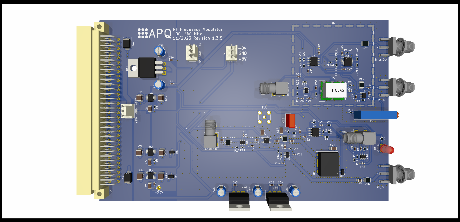
The module features:
Frequency modulated RF output for AOM
Carrier frequency: 110 to 130 MHz
Modulation frequency: 0.1 to 10 MHz
Modulation index: 1.8 max.
Variable gain photodetector amplifier: 0 dB to 20 dB / 100 MHz
Internal demodulation with 4th order filter (0.75 MHz)
Error signal output
Voltage range: ±1 V @ 50 Ohm
Output noise level: <50 nV/√Hz
The VCO type determines the output frequency range of the AOM signal.
110MHz_VCO (master): 100 to 140 MHz
80MHz/200MHz_VCO: 60 to 110 MHz or 140 to 250 MHz. This version can be found here
80MHz/200MHz_VCO_Rev1.2: deprecated version
The design files can be found on the releases page and include the following resources:
The latest revision of those files can be found here.
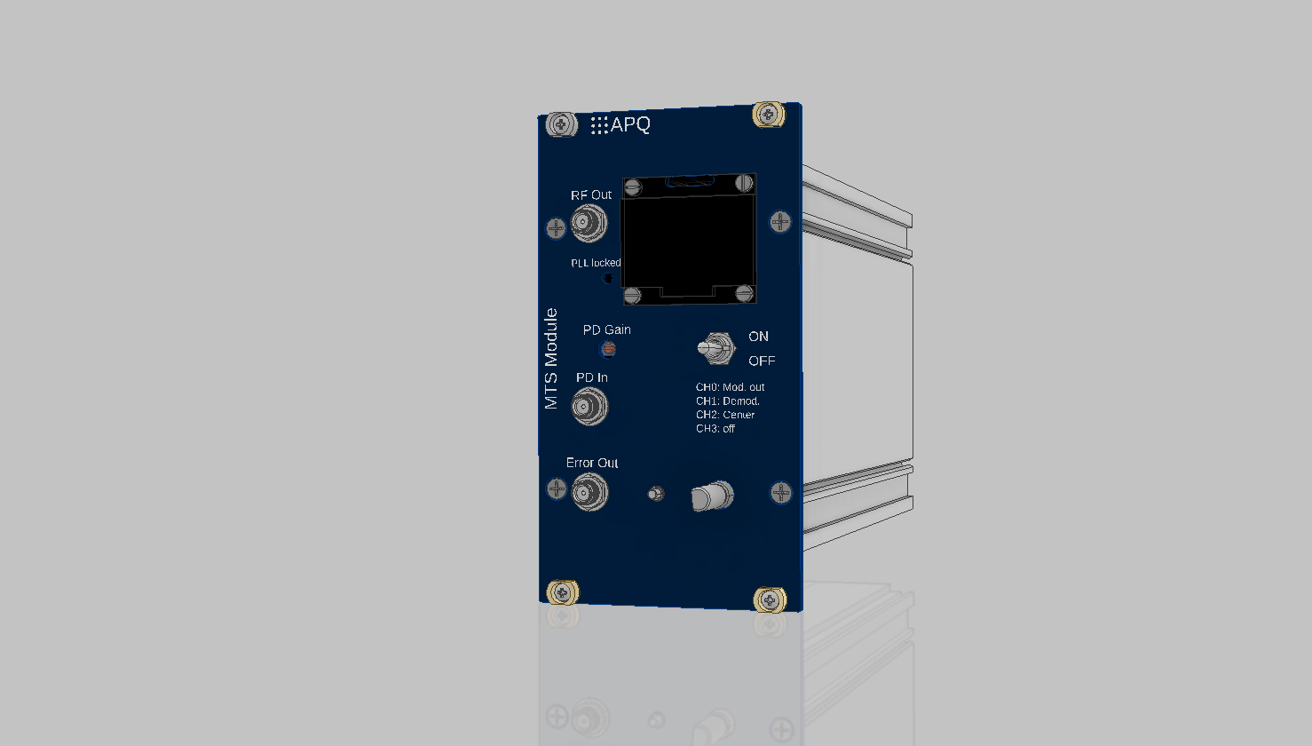
The PCB and the DDS are placed in a standard 19''-rack mount unit. Display and controls of the DDS board are moved to the frontpanel as intended by the manufacturer. Use the rotary encoder breakout board for this task. See frontpanel/ folder for drawings and BOM.
Assembly units (see BOM for details)
MTS module PCB
Fischer rack mount unit
Dual power supply
19-inch rack mount (e.g. Fischer Elektronik BGT384)
T. Preuschoff, Laser Technologies for Applications in Quantum Information Science, Ph.D. thesis, TU Darmstadt, 2023, https://tuprints.ulb.tu-darmstadt.de/23242/
This work is released under the CERN OHL v.1.2 See www.ohwr.org/licenses/cern-ohl/v1.2 or the included LICENSE file for more information.
| Qty | Value | Footprint | References |
|---|---|---|---|
| 21 | 100n | Capacitor_SMD:C_0603_1608Metric | C1, C22, C23, C27, C28, C29, C30, C31, C32, C34, C36, C38, C41, C42, C43, C45 +5 |
| 9 | 390 | Resistor_SMD:R_0603_1608Metric | R5, R14, R17, R25, R30, R31, R32, R34, R35 |
| 6 | 10n(C0G) | Capacitor_SMD:C_0603_1608Metric | C16, C20, C26, C46, C50, C51 |
| 6 | 10u | Capacitor_SMD:C_1210_3225Metric | C2, C3, C4, C10, C11, C12 |
| 6 | 200 | Resistor_SMD:R_0603_1608Metric | R9, R11, R12, R13, R18, R20 |
| 6 | 499 | Resistor_SMD:R_0603_1608Metric | R6, R15, R21, R22, R27, R28 |
| 5 | 100n | Capacitor_SMD:C_1206_3216Metric | C5, C6, C8, C15, C24 |
| 5 | 100u | Capacitor_THT:CP_Radial_D5.0mm_P2.00mm | C33, C35, C37, C39, C40 |
| 5 | 49.9 | Resistor_SMD:R_1210_3225Metric | R3, R10, R16, R19, R29 |
| 5 | OPA695 | Package_TO_SOT_SMD:SOT-23-6 | U5, U9, U13, U14, U17 |
| 4 | 3.3n | Capacitor_SMD:C_0805_2012Metric | C19, C21, C25, C44 |
| 3 | PMEG2010 | Package_TO_SOT_SMD:SOT-23 | D2, D5, D6 |
| 2 | 100 | Resistor_SMD:R_0603_1608Metric | R23, R33 |
| 2 | 2.49k | Resistor_SMD:R_0603_1608Metric | R11A1, R21A1 |
| 2 | 2.94k | Resistor_SMD:R_0603_1608Metric | R12A1, R22A1 |
| 2 | 330p | Capacitor_SMD:C_0603_1608Metric | C13, C14 |
| 2 | 49.9k | Resistor_SMD:R_0603_1608Metric | R1, R4 |
| 2 | ADA4898-2 | Package_SO:SOIC-8-1EP_3.9x4.9mm_P1.27mm_EP2.41x3.81mm | U7, U8 |
| 2 | D_TVS | Diode_SMD:D_SMB | D3, D4 |
| 2 | LT3045xMSE | Package_SO:MSOP-12-1EP_3x4mm_P0.65mm_EP1.65x2.85mm | U2, U3 |
| 1 | +15V GND -15V | Connector_Molex:Molex_KK-254_AE-6410-03A_1x03_P2.54mm_Vertical | J12 |
| 1 | +3.0V | TestPoint:TestPoint_Keystone_5000-5004_Miniature | TP2 |
| 1 | +5V GND -5V | Connector_Molex:Molex_KK-254_AE-6410-03A_1x03_P2.54mm_Vertical | J11 |
| 1 | 140 | Resistor_SMD:R_0603_1608Metric | R7 |
| 1 | 2.74k | Resistor_SMD:R_0603_1608Metric | R31A1 |
| 1 | 20 | Resistor_SMD:R_0603_1608Metric | R24 |
| 1 | 22n | Capacitor_SMD:C_1206_3216Metric | C17 |
| 1 | 287 | Resistor_SMD:R_0603_1608Metric | R8 |
| 1 | 30k | Capacitor_SMD:C_0603_1608Metric | R2 |
| 1 | 330n | Capacitor_THT:C_Rect_L7.2mm_W3.0mm_P5.00mm_FKS2_FKP2_MKS2_MKP2 | C18 |
| 1 | 500 | Potentiometer_THT:Potentiometer_Vishay_43_Horizontal | RV1 |
| 1 | 845 | Resistor_SMD:R_0603_1608Metric | R32A1 |
| 1 | C64AC | Connector_DIN:DIN41612_C_2x32_Male_Horizontal_THT | J1 |
| 1 | CVCO45CL-0100-0140 | footprints:CVCO45CL-0100-0140_DNF | U6 |
| 1 | Center_In | footprints:SMA_Amphenol_901-143_Horizontal_mod | J7 |
| 1 | DDS_Supply | Connector_Molex:Molex_KK-254_AE-6410-03A_1x03_P2.54mm_Vertical | J2 |
| 1 | Demod_In | footprints:SMA_Amphenol_901-143_Horizontal_mod | J4 |
| 1 | Error_Out | Connector_Coaxial:SMA_Amphenol_132289_EdgeMount | J5 |
| 1 | HMC1031 | footprints:MSOP-8_3x3mm_P0.65mm_mod_DNF | U4 |
| 1 | LED | LED_THT:LED_D4.0mm | D1 |
| 1 | LM7808_TO220 | Package_TO_SOT_THT:TO-220-3_Vertical | U12 |
| 1 | LM7812_TO220 | Package_TO_SOT_THT:TO-220-3_Vertical | U10 |
| 1 | LM7908_TO220 | Package_TO_SOT_THT:TO-220-3_Horizontal_TabDown | U11 |
| 1 | LT1568 | Package_SO:SSOP-16_3.9x4.9mm_P0.635mm | U16 |
| 1 | LT3094xMSE | Package_SO:MSOP-12-1EP_3x4mm_P0.65mm_EP1.65x2.85mm | U1 |
| 1 | Logo_APQ | footprints:APQ-Logo | LOGO1 |
| 1 | Logo_Open_Hardware_Small | Symbol:OSHW-Logo_5.7x6mm_SilkScreen | LOGO2 |
| 1 | Logo_ROHS | Symbol:RoHS-Logo_6mm_SilkScreen | LOGO5 |
| 1 | Mod_In | footprints:SMA_Amphenol_901-143_Horizontal_mod | J9 |
| 1 | PD_In | Connector_Coaxial:SMA_Amphenol_132289_EdgeMount | J3 |
| 1 | PLL | Connector_Coaxial:SMA_Amphenol_901-144_Vertical | J8 |
| 1 | RF_Out | Connector_Coaxial:SMA_Amphenol_132289_EdgeMount | J10 |
| 1 | RF_Shield_One_Piece | RF_Shielding:Laird_Technologies_BMI-S-107_44.37x44.37mm | J6 |
| 1 | SYPD-1 | footprints:Mini-Circuits_TTT167_LandPatternPL-079_DNF | U15 |
TU-Darmstadt-APQ/PDH-module
Produces a PDH error-signal using MiniCircuits SYPD-1+ phase detector and LT1568 4th order low-pass filter. To be used with a AD9959 DDS board.


oguzhanbaser/GalvoScanner
Gazebo-Sim/ mytestpkg/ CMakeLists.txt (ROS paketi derleme tanımı) package.xml (ROS paket meta verisi) launch/cameragazebo.launch (Kamera modelini Gazebo’da başlatma) urdf/cameramodel.xacro (Parametrik kamera URDF/Xacro…

TU-Darmstadt-APQ/SFH203_photodetector
Low-noise transimpedance amplifier optimized for the photodiode SFH203.


CarlosCraveiro/einstein-boltzmann
Remake of the board of the 5-th EPO (2017), using KiCAD 7.0, to measure the Boltzmann constant through the analysis of the thermal noise of a resistor.


agranlund/raven
Homemade MC68060 + DSP56303 Atari-compatible computer. Hardware, firmware, and software stack
It measures 160 × 100 mm and has 2 copper layers, 1.6 mm thick.
131 parts, built around the OPA695ID, ADA4898-2YRD, CVCO45CL-0100-0140 and SYPD-1. The full list of its parts is on this page, with links to each part's symbol and footprint where PCBKit's library has them.
From the TU-Darmstadt-APQ/MTS_module repository on GitHub, at the commit this page was made from: the board is KiCad/MTS_module.kicad_pcb and its schematic KiCad/MTS_module.kicad_sch. PCBKit opens the board in the browser, with nothing to install.
Its repository states no licence, so its author keeps all rights: ask TU-Darmstadt-APQ before reusing the design.