2 layers73.5 × 37.5 mm

 TLNKhanh/OmniDrive1
A general-purpose dual motor driver board with ESP32.
OmniDrive is an open-source printed circuit board by TLNKhanh, from the TLNKhanh/OmniDrive repository on GitHub, published under the MIT licence. It is a 2-layer board of 45 × 59.5 mm with 79 parts on 94 nets, routed with 1,614 tracks and 158 vias.
It is built around the CH340C, ESP32-WROOM-32E and DRV8833PWP, with the CH224K, INA219AID and ME6211C33M5G-N among its other parts. Its parts include 26 capacitors, 14 resistors, 9 ICs, 7 connectors and 5 diodes. It belongs with the robots and motor control boards and the ESP32 boards of this library.


Dual H-bridge motor driver + ESP32 + USB-C PD, squeezed into a 45×59.5mm 2-layer board.
I wanted a board that could work with a single USB-C port and have it drive two motors (or 2 pairs if configured) while able to measure the board's current draw.
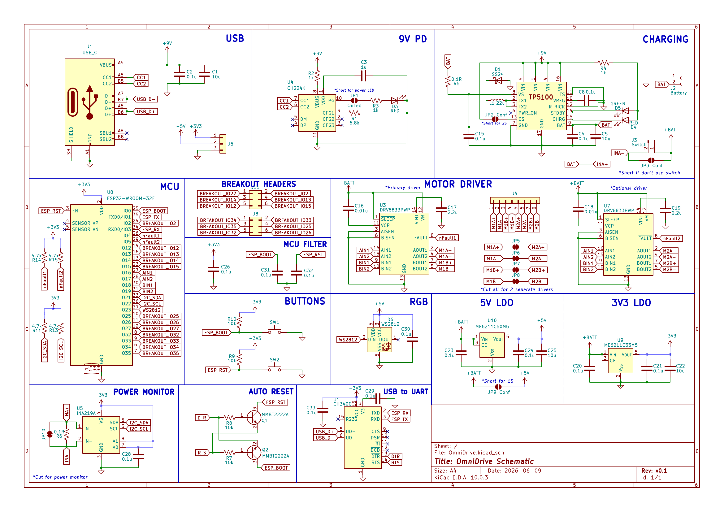 Full schematic — click image or open PDF
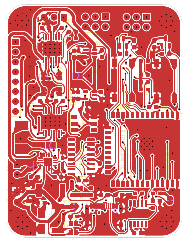 PCB top copper layer — open PDF
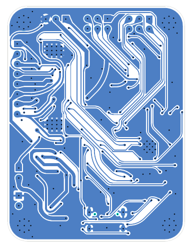 PCB bottom copper layer — open PDF
I wanted something that could serve for multiple RC car or stepper driving projects without having to combine separate modules.
| Function | Component |
|---|---|
| MCU | ESP32-WROOM-32E |
| Motor drivers | 2× DRV8833 (HTSSOP-16 with thermal pad) |
| USB-C PD | CH224K sink, negotiates 9V |
| Current sense | INA219, 0.1Ω shunt, I2C |
| USB-UART | CH340C with auto DTR/RTS |
| Logic power | ME6211C50 (5V), ME6211C33 (3.3V) |
| Breakout | 12 GPIO through 2x 3x2 header, Power through 1x 3x1 header |
| PCB | 2-layer, 1.6mm FR4, 45×59.5mm |
USB-C VBUS → CH224K negotiates voltage → +BATT rail
+BATT splits three ways:
Motor current goes through a shared 0.1Ω sense resistor before reaching the drivers, so the INA219 sees total bus current. Per-motor would need two INA219s (maybe for later).
A few things I'll change next version:
The ME6211C33 is rated for 500mA and ESP32 can spike past that during WiFi TX. On a long USB-C cable with some voltage drop, the battery rail might sag enough to make the 3.3V regulator drop out. An AP2112 or similar low-dropout part would be safer.
Didn't add TVS diodes on the USB-C CC/D+/D- lines or the motor outputs
As mentioned, only total motor current. Can't tell which motor is drawing what.
hardware/
├── schematic.pdf          — full schematic (click to view)
├── PCB_Top.pdf            — top copper render
├── PCB_Bottom.pdf         — bottom copper render
├── gerbers.zip            — Gerbers + drill files
├── bom.csv                — BOM for JLCPCB assembly
├── pick-place.csv         — centroid file
├── kicad/                 — source KiCad project
└── photos/ — PNG renders of schematic + PCB| Qty | Value | Footprint | References |
|---|---|---|---|
| 16 | 0.1u | Capacitor_SMD:C_0603_1608Metric_Pad1.08x0.95mm_HandSolder | C2, C4, C6, C8, C15, C20, C21, C23, C24, C26, C28, C29, C30, C31, C32, C33 |
| 5 | 10u | Capacitor_SMD:C_0603_1608Metric_Pad1.08x0.95mm_HandSolder | C1, C5, C7, C22, C25 |
| 5 | BridgedJumper | Jumper:SolderJumper-2_P1.3mm_Bridged_RoundedPad1.0x1.5mm | JP5, JP6, JP7, JP8, JP10 |
| 4 | 10k | Resistor_SMD:R_0603_1608Metric_Pad0.98x0.95mm_HandSolder | R7, R8, R9, R10 |
| 4 | 4.7k | Resistor_SMD:R_0603_1608Metric_Pad0.98x0.95mm_HandSolder | R11, R13, R14, R15 |
| 4 | MountingHole_2.2mm_M2_Pad_Via | MountingHole:MountingHole_2.2mm_M2_Pad_Via | HoleA, HoleB, HoleC, HoleD |
| 3 | 1k | Resistor_SMD:R_0603_1608Metric_Pad0.98x0.95mm_HandSolder | R2, R3, R4 |
| 3 | Conf | Jumper:SolderJumper-2_P1.3mm_Open_TrianglePad1.0x1.5mm | JP2, JP3, JP9 |
| 2 | 0.01u | Capacitor_SMD:C_0603_1608Metric_Pad1.08x0.95mm_HandSolder | C16, C18 |
| 2 | 0.1R | Resistor_SMD:R_2512_6332Metric_Pad1.40x3.35mm_HandSolder | R5, R6 |
| 2 | 2.2u | Capacitor_SMD:C_0603_1608Metric_Pad1.08x0.95mm_HandSolder | C17, C19 |
| 2 | Conn_02x03_Odd_Even | Connector_PinHeader_2.54mm:PinHeader_2x03_P2.54mm_Vertical | J8, J11 |
| 2 | DRV8833PWP | Package_SO:HTSSOP-16-1EP_4.4x5mm_P0.65mm_EP3.4x5mm_Mask2.46x2.31mm_ThermalVias | U3, U7 |
| 2 | MMBT2222A | Package_TO_SOT_SMD:SOT-23 | Q1, Q2 |
| 2 | RED | LED_SMD:LED_0603_1608Metric_Pad1.05x0.95mm_HandSolder | D3, D4 |
| 2 | SW_Push | Button_Switch_SMD:SW_Push_1P1T_NO_E-Switch_TL3301NxxxxxG | SW1, SW2 |
| 1 | 1u | Capacitor_SMD:C_0603_1608Metric_Pad1.08x0.95mm_HandSolder | C3 |
| 1 | 22u | Inductor_SMD:L_Changjiang_FXL0630 | L1 |
| 1 | 6.8k | Resistor_SMD:R_0603_1608Metric_Pad0.98x0.95mm_HandSolder | R1 |
| 1 | Battery | Connector_PinHeader_2.54mm:PinHeader_1x02_P2.54mm_Vertical | J2 |
| 1 | CH224K | Package_SO:SSOP-10-1EP_3.9x4.9mm_P1mm_EP2.1x3.3mm | U4 |
| 1 | CH340C | Package_SO:SOIC-16_3.9x9.9mm_P1.27mm | U1 |
| 1 | Conn_01x03 | Connector_PinSocket_2.54mm:PinSocket_1x03_P2.54mm_Vertical | J5 |
| 1 | Conn_01x08 | Connector_PinSocket_2.54mm:PinSocket_1x08_P2.54mm_Vertical | J4 |
| 1 | ESP32-WROOM-32E | RF_Module:ESP32-WROOM-32E | U8 |
| 1 | GREEN | LED_SMD:LED_0603_1608Metric_Pad1.05x0.95mm_HandSolder | D5 |
| 1 | INA219A | Package_TO_SOT_SMD:SOT-23-8 | U5 |
| 1 | ME6211C33M5 | Package_TO_SOT_SMD:SOT-23-5 | U9 |
| 1 | ME6211C50M5 | Package_TO_SOT_SMD:SOT-23-5 | U10 |
| 1 | OnLed | Jumper:SolderJumper-2_P1.3mm_Bridged_RoundedPad1.0x1.5mm | JP1 |
| 1 | SS24 | Diode_SMD:D_SMA | D1 |
| 1 | Switch | Connector_PinHeader_2.54mm:PinHeader_1x02_P2.54mm_Vertical | J3 |
| 1 | USB_C | Connector_USB:USB_C_Receptacle_HCTL_HC-TYPE-C-16P-01A | J1 |
| 1 | WS2812 | LED_SMD:LED_WS2812_PLCC6_5.0x5.0mm_P1.6mm | D6 |
| 1 | ~ | Package_DFN_QFN:NXP_VQFN-16-1EP_4x4mm_P0.65mm_EP2.1x2.1mm | U2 |


sean618/MakerTiles
Modular STM32 electronic-tile system: hardware, firmware, the MicroBus + Field Protocol stack, and a Python daemon.
It measures 45 × 59.5 mm and has 2 copper layers, 1.6 mm thick.
79 parts, built around the CH340C, ESP32-WROOM-32E, DRV8833PWP and CH224K. The full list of its parts is on this page, with links to each part's symbol and footprint where PCBKit's library has them.
From the TLNKhanh/OmniDrive repository on GitHub, at the commit this page was made from: the board is hardware/kicad/OmniDrive.kicad_pcb and its schematic hardware/kicad/OmniDrive.kicad_sch. PCBKit opens the board in the browser, with nothing to install.
Its repository publishes it under the MIT licence: you may reuse it on that licence's terms (keep the author's notice, and for a copyleft licence share your changes alike).