2 layers50 × 66 mm

 SteveSyfuhs/UsbSound12
A custom-made USB sound card for Balanced Audio
UsbSound is an open-source printed circuit board by SteveSyfuhs, from the SteveSyfuhs/UsbSound repository on GitHub, published under the MIT licence. It is a 4-layer board of 121.6 × 79.8 mm with 91 parts on 112 nets, routed with 763 tracks and 398 vias.
It is built around the STM32F405RGT6, NE5534D and ICL7660N, with the PCM1795DB, USBLC6-2SC6 and B5819W among its other parts. Its parts include 45 capacitors, 20 resistors, 9 ICs, 5 connectors and 4 diodes. It belongs with the audio and music boards and the STM32 boards of this library.


A custom-made USB sound card for Balanced Audio.
My current USB DAC isn't great and instead of just buying a new one I thought I'd try and waste some serious engineering hours learning how to build one instead.
My existing DAC uses the PCM2705 chip to handle both the USB and DAC side of things. It's fine, I guess, but it has some annoying quirks.
First, you have to bolt on an additional chip to do silly things like control the USB descriptors. Absent that you're left with this annoying string with two trailing spaces (probably nulls?). Clearly not the end of the world, but I might as well aim for perfect.

Second, the output from the chip is only single-ended so it requires extra effort to make a good differential output. This existing device is using a transformer (two, on per channel) to generate the differential pair, which is great for isolation, but transformers are notorious for distortion at high frequency.
Curiously this device also doesn't produce a great differential output at 1000hz.

Channel A (blue) is the positive leg and Channel B (red) is the negative leg. Channel 3 (magenta?) is A+B, which ideally should sum to zero, not ~16mV RMS.
To be clear: I really have no idea what I'm doing so my choice of parts or circuit are driven by the last thing I learned about. If there's clearly a better way to do something then please let me know.
It happened to be the chip used in Phil's video where learned to use Kicad and it happens to support I2S. It's incredibly powerful for the use case here, and a less powerful device could be used instead. That said, it could make for a useful platform for building out digital filters and stuff.
I like the low distortion and noise floor it provides and since I'm starting with a blank canvas why not start with something that's overkill? I can only make it worse.
Note: the audible differences between this and other DACs is ultimately going to be nil so there will be no notable benefit. I'm doing this because I can.
The PCM1795 uses that as a baseline for the measured circuits so it's a helpful starting place. I will probably switch these out for LM4562's in the near future once I test out the board and do initial measurements to compare against spec. The LM4562s have lower distortion and noise floor, and more interestingly contain two op-amps in the package so I can reduce the circuit footprint.
Again, I can only make things worse.
The speakers I'll be driving are studio monitors and they require a balanced XLR connection.
Eventually, probably. The micro supports 3 I2S lines, and each I2S line supports two channels out and one in.
Maybe. See the output section.
Ideally it'll show up as a USB audio device and all major operating systems will just pick it up.
A work in progress. Ideal testing should measure:
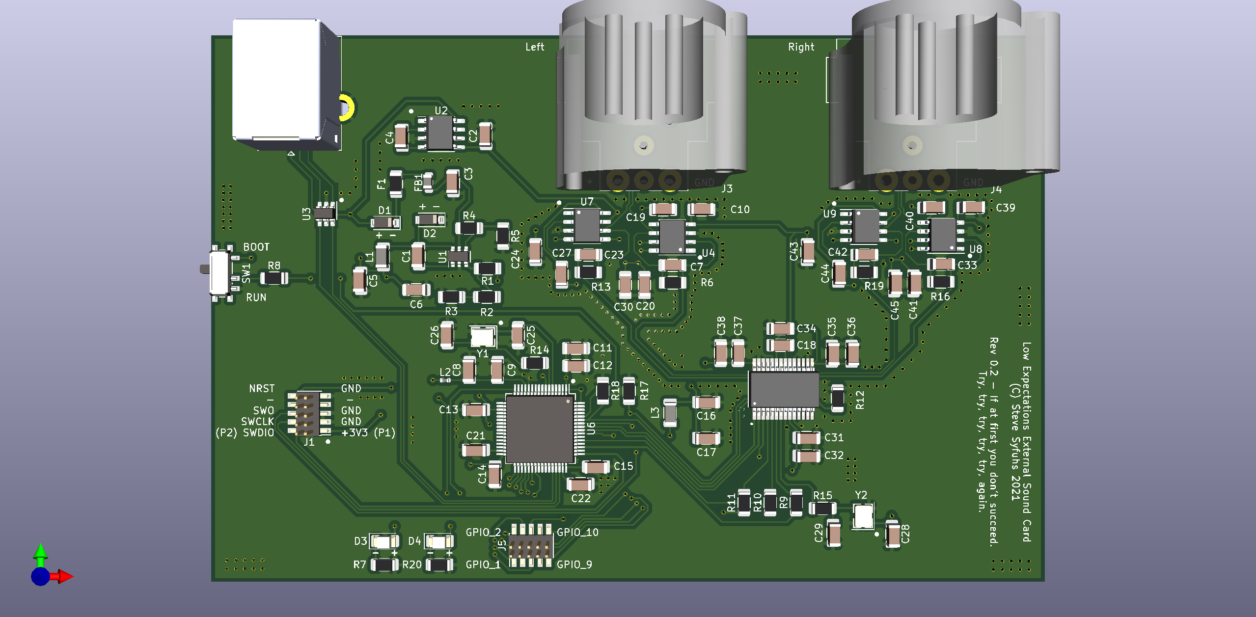
| Qty | Value | Footprint | References |
|---|---|---|---|
| 10 | 10u | Capacitor_SMD:C_1206_3216Metric | C1, C2, C3, C4, C5, C6, C32, C34, C36, C38 |
| 8 | 0u1 | Capacitor_SMD:C_1206_3216Metric | C10, C20, C24, C30, C39, C41, C43, C45 |
| 4 | 100n | Capacitor_SMD:C_1206_3216Metric | C12, C13, C14, C15 |
| 4 | 12p | Capacitor_SMD:C_1206_3216Metric | C25, C26, C28, C29 |
| 4 | 22pF | Capacitor_SMD:C_1206_3216Metric | C19, C27, C40, C44 |
| 4 | 2700pF | Capacitor_SMD:C_1206_3216Metric | C7, C23, C33, C42 |
| 4 | 820 | Resistor_SMD:R_1206_3216Metric | R6, R13, R16, R19 |
| 4 | NE5534 | Package_SO:SOIC-8-1EP_3.9x4.9mm_P1.27mm_EP2.29x3mm | U4, U7, U8, U9 |
| 3 | 0.1u | Capacitor_SMD:C_1206_3216Metric | C31, C35, C37 |
| 3 | 27 | Resistor_SMD:R_1206_3216Metric | R9, R10, R11 |
| 2 | 0 | Resistor_SMD:R_1206_3216Metric | R14, R15 |
| 2 | 10k | Resistor_SMD:R_1206_3216Metric | R8, R12 |
| 2 | 10n | Capacitor_SMD:C_1206_3216Metric | C9, C17 |
| 2 | 1u | Capacitor_SMD:C_1206_3216Metric | C8, C16 |
| 2 | 2k2 | Resistor_SMD:R_1206_3216Metric | R7, R20 |
| 2 | 2u2 | Capacitor_SMD:C_1206_3216Metric | C21, C22 |
| 2 | 4k7 | Resistor_SMD:R_1206_3216Metric | R17, R18 |
| 2 | B5819W | Diode_SMD:D_SOD-123 | D1, D2 |
| 2 | Red | LED_SMD:LED_1206_3216Metric | D3, D4 |
| 2 | SWD | Connector_PinHeader_1.27mm:PinHeader_2x05_P1.27mm_Vertical_SMD | J1, J5 |
| 1 | 100k | Resistor_SMD:R_1206_3216Metric | R4 |
| 1 | 10u | Inductor_SMD:L_1206_3216Metric | L1 |
| 1 | 15k | Resistor_SMD:R_1206_3216Metric | R2 |
| 1 | 16MHz | Crystal:Crystal_SMD_3225-4Pin_3.2x2.5mm | Y1 |
| 1 | 250mA | Fuse:Fuse_1206_3216Metric | F1 |
| 1 | 270 | Resistor_SMD:R_1206_3216Metric | R3 |
| 1 | 36.864MHz | Crystal:Crystal_SMD_3225-4Pin_3.2x2.5mm | Y2 |
| 1 | 39n | Inductor_SMD:L_0402_1005Metric | L2 |
| 1 | 39n | Inductor_SMD:L_1206_3216Metric | L3 |
| 1 | 47k | Resistor_SMD:R_1206_3216Metric | R1 |
| 1 | 47u | Capacitor_SMD:C_1206_3216Metric | C18 |
| 1 | 4u7 | Capacitor_SMD:C_1206_3216Metric | C11 |
| 1 | 600 @ 600MHz | Inductor_SMD:L_0805_2012Metric | FB1 |
| 1 | 68k | Resistor_SMD:R_1206_3216Metric | R5 |
| 1 | BOOT_SELECT | Button_Switch_SMD:SW_SPDT_PCM12 | SW1 |
| 1 | ICL7660 | Package_SO:SOIC-8-1EP_3.9x4.9mm_P1.27mm_EP2.29x3mm | U2 |
| 1 | PCM1795DB | symbols:SOP65P780X200-28N | U5 |
| 1 | STM32F405RGT6 | Package_QFP:LQFP-64_10x10mm_P0.5mm | U6 |
| 1 | USBLC6-2SC6 | Package_TO_SOT_SMD:SOT-23-6 | U3 |
| 1 | USB_B | Connector_USB:USB_B_Lumberg_2411_02_Horizontal | J2 |
| 1 | XLR_L | Connector_Audio:Jack_XLR_Neutrik_NC3MAH_Horizontal | J3 |
| 1 | XLR_R | Connector_Audio:Jack_XLR_Neutrik_NC3MAH_Horizontal | J4 |
| 1 | XRP7659 | Package_SO:TSOP-6_1.65x3.05mm_P0.95mm | U1 |

amrithHN/stm32f4xx_minimal_dev
stm32f4 minimal dev board with few sensors

majdbiw4200/STM32F405RGT-dev-board
STM32 + USB + Buck Converter PCB Design

alphaseneca/pcb_design_repo
A repository for storing and documenting the pcb design files.

pravinsharma15k-ops/STM32F4-Test-Board
STM32F405-based test board designed in KiCad 10, with buck converter, USB, SWD, I2C and UART.

szolotykh/kinisi-motor-controller-board
Kinisi motor controller board based on STM32F405 microcontroller

Codebreaker000/PCB_DESIGNS
Contains all PCB designs with Schematics and Board view file's and both pdf's to understand and gerber files and the view and layout of the PCB's.

It measures 121.6 × 79.8 mm and has 4 copper layers, 4.69 mm thick.
91 parts, built around the STM32F405RGT6, NE5534D, ICL7660N and PCM1795DB. The full list of its parts is on this page, with links to each part's symbol and footprint where PCBKit's library has them.
From the SteveSyfuhs/UsbSound repository on GitHub, at the commit this page was made from: the board is UsbSound.kicad_pcb and its schematic UsbSound.kicad_sch. PCBKit opens the board in the browser, with nothing to install.
Its repository publishes it under the MIT licence: you may reuse it on that licence's terms (keep the author's notice, and for a copyleft licence share your changes alike).