Skip to the content
4 layers150 × 90 mmMisrc v2.5-rounded, the printed circuit board in 3D

Misrc v2.5-rounded

Stefan-Olt/MISRC236

MISRC Is a multi channel RF capture device for FM RF, S-Video, CVBS RAW capture and anything else, but intended and supported for the decode family of projects vhs-decode, ld-decode, hifi-decode.

Size
150 × 90 mm
Copper layers
4
Thickness
1.6 mm
Parts
328
Nets
240
Pads
995
Tracks, vias
1,590, 1,628
Pours
5
Routed
Yes
KiCad
KiCad 9.0 (file 20241229)
Created
28 Dec 2023
Updated
27 Aug 2026

Overview

Misrc v2.5-rounded is an open-source printed circuit board by Stefan-Olt, from the Stefan-Olt/MISRC repository on GitHub, published under the CC-BY-4.0 licence. It is a 4-layer board of 150 × 90 mm with 328 parts on 240 nets, routed with 1,590 tracks and 1,628 vias.

It is built around the 74VHC541D, AD8138ARZ and LM2662M, with the LMK1C1106PW, AD9235 and ADA4004-1ARZ among its other parts. Its parts include 156 capacitors, 82 resistors, 15 ICs, 14 diodes and 14 inductors. It belongs with the audio and music and radio and wireless boards and the FPGA and CPLD boards of this library.

Main components

12

README

README.md

MISRC - Multi Input Simultaneous Raw RF Capture

Hardware - Firmware - Software - Usage example

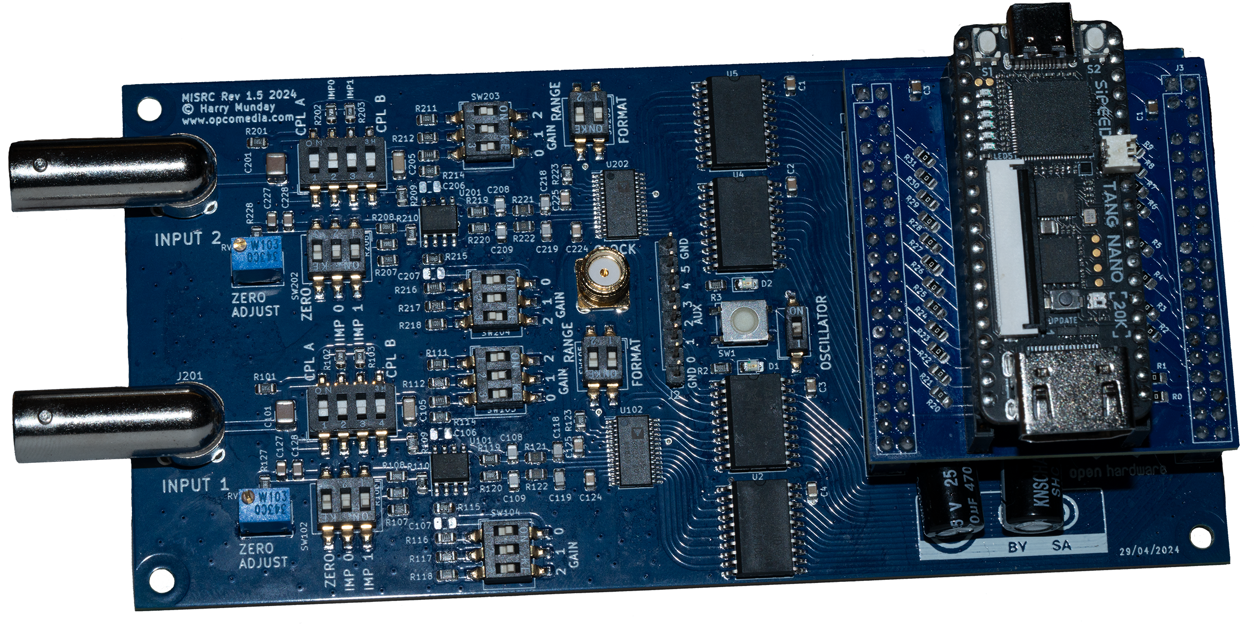
V1.5 with Tang Nano 20k on the FX3 to Tang Nano 20k adapter PCB.

Description

MISRC is a device to capture two signals at 12-bit and up to 40 MSPS (20 Mhz bandwith) (This could be extended to 80 MSPS in the future) and an additional 8-bit's (2-bit's for v2.5) of binary (auxiliary data) over USB 3.0.

It is intended to capture modulated tape deck RF for software demodulation, but also baseband CVBS/S-Video (Composite) video signals for software decoding, and can be used as a direct stream Oscilloscope but limited to 2vpp input voltage.

The Decode Projects:

Provide decoding for a wide range of videotape formats, HiFi audio and even RAW or Baseband composite decoding with free and powerful software time base correction with full post filtering control over the signal processing.


Media RF TypeMISRC Support
Video FM RFYes
HiFi FM RFYes
CVBS RFYes
S-Video RFYes

Possible capture examples:

  • Capture 2x CVBS
  • Capture 1x S-Video (Y & C)
  • Capture Video RF and HiFi RF simultaneously
  • Capture Video RF and CVBS simultaneously
  • Capture 4ch of 24-bit 48khz audio with AUX pins via integrated or external clock-locked ADCs See MISRC Clockgen [blocked]

[!NOTE] It may be useful for other purposes as well, as it is built as a generic ADC with configurable filtering.

Hardware features

  • Dual ADC / Dual Input (BNC Connectors)
  • 6 Extra Aux inputs for audio ADC modules etc
  • Two 12-bit 40msps ADCs: AD9235
  • Selectable input gain (8 steps) (using AD8138 op-amp)
  • Selectable ADC range (1V or 2V)
  • Selectable input impedance (75, 50, 37.5 and 30 ohms)
  • DC or AC (pre- or post-termination) coupling
  • Zero-adjust to compensate DC offset
  • Latching clipping indicator (automatic resetting on v2.5)
  • Clock source selectable: USB PLL (FX3 setup), crystal or external
  • Clock output SMA for external devices (In/Out for V2.5)
  • Melted PCB Traces

Costs

[!TIP]
You can support the development and production of the MISRC platform here.

  • PCB: 20-30USD
  • Parts 100-150USD
  • Single unit total production cost is currently 260-350USD. (USA costs vastly higher for direct fab)
  • Order a V1.5 Development MISRC

[!NOTE]
These are off-shelf PCBs and USB 3.0 devices that you add to the MISRC PCB.

[!TIP]
You can order pre-made adaptor PCBs here for V1.5 boards with the headers for the FX3.

Firmware (Tang Nano 20k)

To be able to use the Tang Nano 20k to send data over HDMI, it needs to be flashed once via USB connection:

Firmware Flashing
  1. Download the firmware, see releases for the latest version.

  2. Install openFPGALoader

  3. Connect your Tang to a USB 3.0 port via its Type-C, it will need this for 5V power after flashing, but not data from the MISRC.

    Run via terminal inside the firmware directory

    text
    openFPGALoader -b tangnano20k -f hsdaoh_nano20k_misrc.fs

You have flashed your Tang Nano 20k!

Software

MISRC GUI is built for cross platform use, all binary's bundle both CLI and GUI.

For detailed information of the original core tools, see the misrc_tools readme.

Windows Driver Setup

For misrc_capture or misrc-gui to be able to access the MS2130 or MS2131 capture device, you need to install a generic driver:

Firstly download Zadig

Force the installation of WinUSB (v6.1.7600.16385) or libusb-win32 (v1.2.6.0) driver on your MS2130/MS2131 adapter, on interface 0 leave interface 4 alone.

text
Interface 0 - USB Video
Interface 4 - HIDDevice
Install macOS

For macOS you do not need to install anything.

  • macOS versions 10.15 and 11: You can directly execute misrc_capture.
  • macOS 12 and later: You have to run misrc_capture as root (sudo). misrc-gui automatically prompts when opened. This is a new security feature by Apple, there is currently no way to bypass it...
Install Linux

If you want to run misrc_capture as root, there is no need to install anything on Linux.

But for misrc_capture to be able to access the MS2130 capture device without root privilege (sudo), you may need to install a udev-rule and add the user that will use misrc_capture to the plugdev-group. The pre-build packages contains the script install-udev-rules.sh. On execution (double-click the file or run ./install-udev-rules.sh on the command line) it will install the rule and add the current user to the plugdev group.

Setting Up the MISRC

  • Connect your 5V USB-C to the Tang Nano for power.

  • Connect your HDMI cable (copper or fiber) to your Tang Nano for data output to the MS2130 or MS2131.

  • Connect the desired sources to the BNC inputs and select suitable impedance and AC or DC coupling.

[!NOTE] You will want to use 2vpp range rather than 1vpp range to make use of the 12-bits range.

Install OCENAudio or alternatives like Audacity it will see captures as a 40khz 16-bit file.

Run a 3-second test capture in FLAC, to be automatically reloaded for viewing.

text
misrc_capture -p -f -B -t 3 -a test.flac

Start the capturing process for setting the DC offset then gain:

text
- Reset clipping LEDs (always on after start or major adjustment) 
- Increase gain during capture until clipping LED lights up
- Decrease gain one step and reset clipping LED
- Repeat for the second channel if in use.
  • Stop capture and verify levels are acceptable in your audio DAW and the signal is centred.

Once happy, then do a full test capture to verify.

[!CAUTION]

  • NEVER use USB for any other heavy-load task (like external HDD/SSD drives, USB network adaptors, YUV capture devices) during capture.
  • Do not connect/disconnect any other USB device during capture, a dedicated USB 3.0 to 3.2 Gen 2 card is ideal for dedicated capture stations as it ensures dedicated bandwidth/power if you have other items that require USB.

Design

MISRC is loosely based on the Domesday Duplicator (DdD) a legacy LaserDisc capture focused FM RF Archival device.

The MISRC is built around the AD9235 analogue to digital converter by Analog Devices and is heavily based on the evaluation board circuit given in its datasheet with the AD8138 Op-Amp providing adjustable fixed gain.

The MISRC like the DdD it originally used the Cypress FX3 SuperSpeed Explorer board for a USB 3.0 data connection, and using Sigronk for capture, with hopes to not use the DE0 FPGA, this ended with the adoption of the Tang Nano 20k and MS2130 "data over YUV" method being used.

License

The hardware, firmware and software is released under different open-source licenses. You can read the License here

Parts

328
QtyValueFootprintReferences
43100nCapacitor_SMD:C_0603_1608MetricC14, C103, C112, C113, C115, C120, C122, C123, C124, C125, C126, C139, C140, C142, C146, C147 +27
2210µCapacitor_SMD:C_0805_2012MetricC22, C25, C32, C34, C35, C36, C102, C127, C131, C136, C202, C227, C231, C236, C301, C308 +6
211µCapacitor_SMD:C_0603_1608MetricC1, C2, C3, C12, C13, C20, C21, C24, C29, C30, C31, C145, C148, C245, C303, C304 +5
171n/1Capacitor_SMD:C_0603_1608MetricC23, C27, C104, C111, C114, C116, C121, C128, C144, C204, C211, C214, C216, C221, C228, C244 +1
12BAT54Diode_SMD:D_SOD-323D101, D102, D103, D104, D105, D106, D201, D202, D203, D204, D205, D206
1010kResistor_SMD:R_0603_1608MetricR123, R124, R128, R223, R224, R228, R301, R302, R401, R402
9470Resistor_SMD:R_0603_1608MetricR4, R5, R8, R305, R306, R308, R405, R406, R408
810Resistor_SMD:R_0603_1608MetricR6, R11, R12, R13, R16, R17, R127, R227
81kBResistor_SMD:R_0603_1608MetricR104, R105, R111, R116, R204, R205, R211, R216
847BResistor_SMD:R_0603_1608MetricR119, R120, R121, R122, R219, R220, R221, R222
8560nFInductor_SMD:L_1008_2520MetricL103, L104, L105, L106, L203, L204, L205, L206
71000µCapacitor_SMD:CP_Elec_10x12.6C6, C10, C11, C16, C17, C18, C19
61k@100MHz,280@10MHzInductor_SMD:L_0603_1608MetricFB1, FB2, FB3, FB101, FB201, FB301
6940n/1Capacitor_SMD:C_1812_4532MetricC141, C241, C302, C305, C402, C405
5MountingHoleFootprints:caseH10, H11, H12, H13, H14
5SW_DIP_x03Button_Switch_SMD:SW_DIP_SPSTx03_Slide_6.7x9.18mm_W8.61mm_P2.54mm_LowProfileSW2, SW102, SW104, SW202, SW204
4100BResistor_SMD:R_0603_1608MetricR101, R102, R201, R202
4100µCapacitor_SMD:C_1210_3225MetricC101, C143, C201, C243
415pF/1Capacitor_SMD:C_0603_1608MetricC110, C117, C210, C217
41pCapacitor_SMD:C_0603_1608MetricC106, C107, C206, C207
4200pF/1Capacitor_SMD:C_0603_1608MetricC137, C138, C237, C238
4240pF/1Capacitor_SMD:C_0603_1608MetricC108, C109, C208, C209
42k49BResistor_SMD:R_0603_1608MetricR112, R117, R212, R217
4360pF/1Capacitor_SMD:C_0603_1608MetricC132, C133, C232, C233
4390pF/1Capacitor_SMD:C_0603_1608MetricC118, C119, C218, C219
447kResistor_SMD:R_0603_1608MetricR303, R304, R403, R404
4499BResistor_SMD:R_1206_3216MetricR109, R110, R209, R210
449R9BResistor_SMD:R_0603_1608MetricR106, R108, R206, R208
44k99BResistor_SMD:R_0603_1608MetricR113, R118, R213, R218
451pF/1Capacitor_SMD:C_0603_1608MetricC134, C135, C234, C235
4620nFInductor_SMD:L_1008_2520MetricL101, L102, L201, L202
468pF/1Capacitor_SMD:C_0603_1608MetricC129, C130, C229, C230
46k65BResistor_SMD:R_1206_3216MetricR114, R115, R214, R215
474VHC541Package_SO:SOIC-20W_7.5x12.8mm_P1.27mmU2, U3, U4, U5
4MountingHoleMountingHole:MountingHole_3.2mm_M3H1, H2, H3, H4
4SW_DIP_x04Button_Switch_SMD:SW_DIP_SPSTx04_Slide_6.7x11.72mm_W8.61mm_P2.54mm_LowProfileSW101, SW103, SW201, SW203
2100Resistor_SMD:R_0603_1608MetricR2, R3
2100µFootprints:L_Bourns-SRU8043_2L1, L2
210kPotentiometer_THT:Potentiometer_Bourns_3266W_VerticalRV101, RV201
2150BResistor_SMD:R_0603_1608MetricR107, R207
2300BResistor_SMD:R_0603_1608MetricR103, R203
230kResistor_SMD:R_0603_1608MetricR14, R15
2470n/1Capacitor_SMD:C_2220_5750MetricC105, C205
247µCapacitor_SMD:C_1210_3225MetricC8, C28
26k8Resistor_SMD:R_0603_1608MetricR126, R226
2AD8138ARZPackage_SO:SO-8_3.9x4.9mm_P1.27mmU101, U201
2AD9235Package_SO:TSSOP-28_4.4x9.7mm_P0.65mmU102, U202
2ADA4004-1Package_TO_SOT_SMD:SOT-23-5U203, U204
2AO3400APackage_TO_SOT_SMD:SOT-23Q3, Q5
2AO3401APackage_TO_SOT_SMD:SOT-23Q4, Q6
2BNC_RosenbergerFootprints:BNC_Right_Angle-DOSIN-801-0050_5pinJ101, J201
2LEDFootprints:LED_XL1606D1, D2
2PCM1802DBRPackage_SO:SSOP-20_5.3x7.2mm_P0.65mmU301, U401
130kBResistor_SMD:R_0603_1608MetricR7
1CC LicenceFootprints:CC LicenceH6
1Conn_01x01_ShieldedFootprints:SMA_Amphenol_901-144_Vertical2J4
1Conn_01x05_SocketConnector_PinSocket_2.54mm:PinSocket_1x05_P2.54mm_HorizontalJ5
1ECS-TXO-2520-33-400-AN-TROscillator:Oscillator_SMD_ECS_2520MV-xxx-xx-4Pin_2.5x2.0mmY1
1FZT690BPackage_TO_SOT_SMD:SOT-223-3_TabPin2Q1
1FZT790APackage_TO_SOT_SMD:SOT-223-3_TabPin2Q2
1GPIFII_J6Connector_PinHeader_2.54mm:PinHeader_2x20_P2.54mm_VerticalJ1
1GPIFII_J7Connector_PinHeader_2.54mm:PinHeader_2x20_P2.54mm_VerticalJ2
1KLP42X-61-WW_RRFootprints:KLP42X61WWRRJ301
1LM2662Package_SO:SOIC-8_3.9x4.9mm_P1.27mmU6
1LMK1C1106Package_SO:TSSOP-14_4.4x5mm_P0.65mmU9
1LT3042xMSEPackage_SO:MSOP-10-1EP_3x3mm_P0.5mm_EP1.68x1.88mmU7
1MISRC-Gain_SettingsFootprints:misrc_settingsH5
1MISRC-Input_CircuitFootprints:misrc_input_circuitH8
1MISRC-Settings-CplFootprints:misrc_settings_cplH9
1OSHW LogoSymbol:OSHW-Logo_5.7x6mm_SilkScreenH7
1~Oscillator:Oscillator_SMD_SiT_PQFN-4Pin_2.0x1.6mmY2
1~Oscillator:Oscillator_SMD_EuroQuartz_XO53-4Pin_5.0x3.2mmY3

More from Stefan-Olt/MISRC

2
  • 2 layers146.2 × 72.6 mmMisrc v1.5a, the printed circuit board in 3D

    Misrc v1.5a

    Stefan-Olt/MISRC

    MISRC Is a multi channel RF capture device for FM RF, S-Video, CVBS RAW capture and anything else, but intended and supported for the decode family of projects vhs-decode, ld-decode, hifi-decode.

    194 parts236CC-BY-4.0
  • 2 layers54.4 × 49.3 mmFx3 tn20k adapter, the printed circuit board in 3D

    Fx3 tn20k adapter

    Stefan-Olt/MISRC

    MISRC Is a multi channel RF capture device for FM RF, S-Video, CVBS RAW capture and anything else, but intended and supported for the decode family of projects vhs-decode, ld-decode, hifi-decode.

    44 parts236CC-BY-4.0

Similar boards

  • 2 layers146.2 × 72.6 mmMISRC v2.1, the printed circuit board in 3D

    MISRC v2.1

    peppi001/MISRC-PCM

    226 parts2
  • 4 layers105.5 × 63.5 mmENIAC, the printed circuit board in 3D

    ENIAC

    parsa-novin/UGA-IREC

    149 parts2
  • 4 layers200 × 50 mmVFD Clock, the printed circuit board in 3D

    VFD Clock

    drewsum/VFD_Clock

    A VFD clock centered around a PIC32MZ EF microcontroller

    486 parts1
  • 2 layersNotahawk, the printed circuit board in 3D

    Notahawk

    bimmui/notahawk

    50 parts
  • 4 layers200 × 50 mmNixie Clock Core, the printed circuit board in 3D

    Nixie Clock Core

    drewsum/Nixie_Clock

    A nixie clock designed around a PIC16LF1519

    338 parts
  • 4 layers40 × 40 mmCommsRev0, the printed circuit board in 3D

    CommsRev0

    Kmshanley/PicoSat-Initiative

    The pocket cube standard requires satellites to be 5x5x5cm and under 250 grams. Upon completion of this Wentworth PicoSat it will become one of the smallest satellites capable of high resolution imagery from LEO.

    39 parts3GPL-3.0
  • 2 layers50 × 50 mmTdstatv3, the printed circuit board in 3D

    Tdstatv3

    thomasdob/tdstatv3

    A USB-controlled potentiostat/galvanostat for thin-film battery characterization

    71 parts23GPL-3.0
  • 2 layers88.9 × 73.7 mmHeadphone amp v2, the printed circuit board in 3D

    Headphone amp v2

    r4ptor/headphone-DAC-with-amp

    A portable (headphone) USB DAC with a separate conversion stage.

    95 parts3GPL-3.0

Questions

How big is the Misrc v2.5-rounded PCB?

It measures 150 × 90 mm and has 4 copper layers, 1.6 mm thick.

What parts does the Misrc v2.5-rounded use?

328 parts, built around the 74VHC541D, AD8138ARZ, LM2662M and LMK1C1106PW. The full list of its parts is on this page, with links to each part's symbol and footprint where PCBKit's library has them.

Where can I download the Misrc v2.5-rounded KiCad files?

From the Stefan-Olt/MISRC repository on GitHub, at the commit this page was made from: the board is hardware/kicad/dev/misrc_v2.5-rounded.kicad_pcb and its schematic hardware-extra/fx3-tangnano20k-adapter/kicad/fx3_tn20k_adapter.kicad_sch. PCBKit opens the board in the browser, with nothing to install.

Can I use the Misrc v2.5-rounded design in my own project?

Its repository publishes it under the CC-BY-4.0 licence: you may reuse it on that licence's terms (keep the author's notice, and for a copyleft licence share your changes alike).