14 layers273 × 186 mm
Dacboard
ShizeChe/unispin
Unified control architecture for spin qubits in quantum dot devices
388 parts18
 ShizeChe/unispin18
Unified control architecture for spin qubits in quantum dot devices
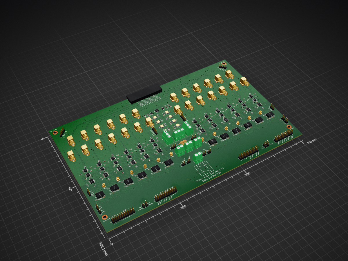
Dacboard is an open-source printed circuit board by ShizeChe, from the ShizeChe/unispin repository on GitHub. It is a 16-layer board of 302 × 188.1 mm with 481 parts on 1,161 nets, routed with 5,071 tracks and 5,191 vias.
It is built around the AD5791BRUZ, AD8675ARZ and ISO6761FQDWRQ1, with the RFPC-SMA28-F, ASP-184330-01 and DLS3XS6AK44X among its other parts. Its parts include 213 capacitors, 105 ICs, 88 resistors and 71 connectors.


A unified quantum control platform for quantum dot spin qubits
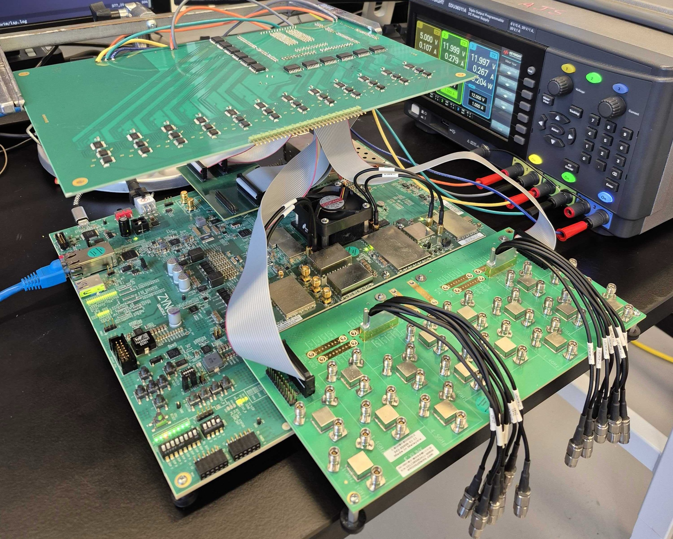
Unispin is a unified quantum control platform designed specifically for quantum dot spin qubits. Its goal is to reduce control stack complexity and cost while improving performance by integrating all the requried control resources onto a single FPGA. With the two custom PCBs (FMC breakout board and low-noise DAC board), the current configuration has:
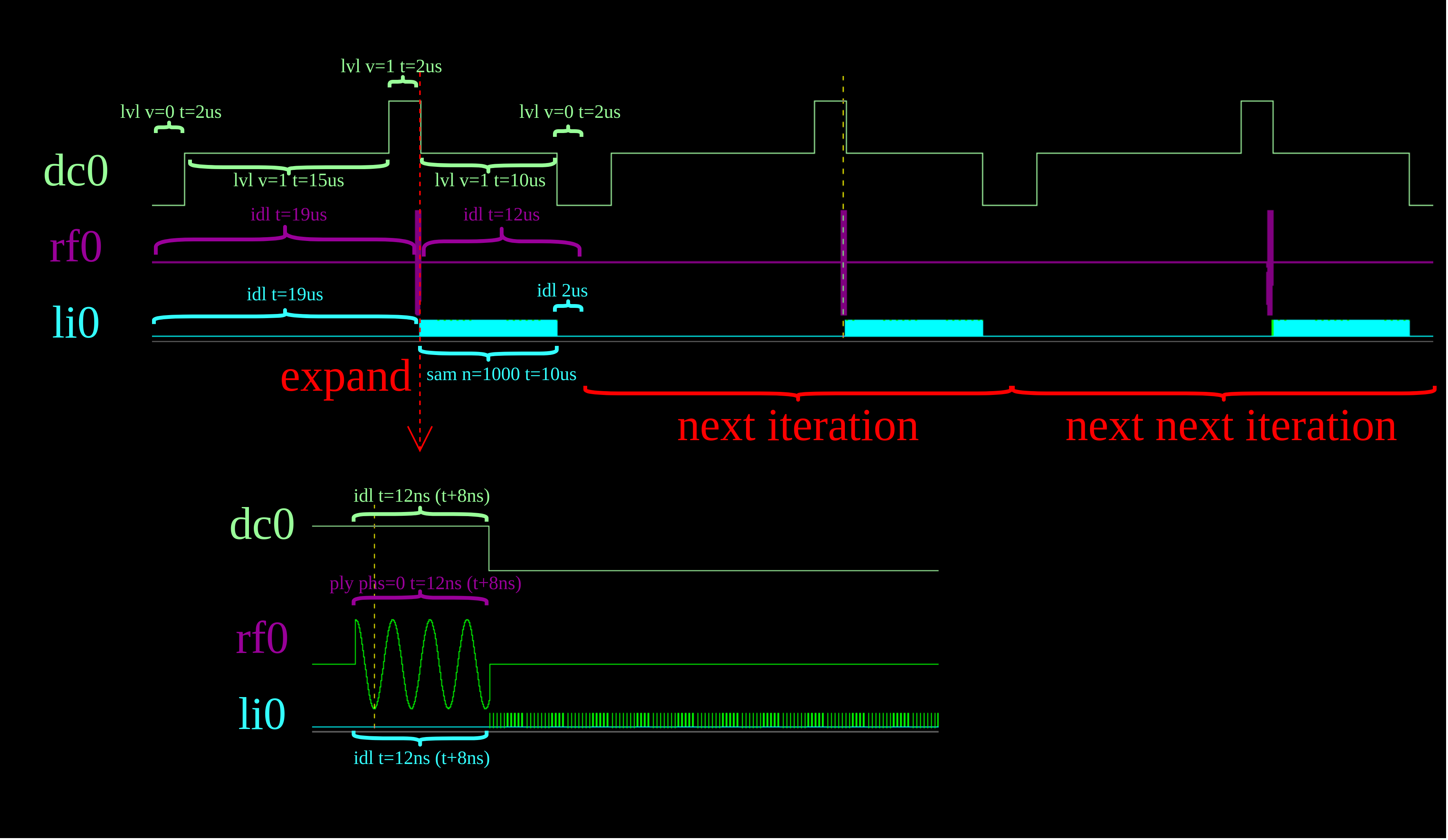
Each signal and measurement channel has its own dedicated, fully-pipelined control core. Each core can be programmed to iteratively executes a sequence of custom assembly instructions with cycle-precise timing. The annotated pulse experiment assembly program and waveform below demonstrates this execution model.
.program rf0                 # program for RF channel 0
.fnco 10MHz                  # NCO is 10MHz
.repeat 100                  # repeats 100 times
    idl t=19us (arm)         # idle for 19us
    ply phs=0 t=12ns (t+8ns) # play the NCO tone for 12ns (increment the pulse duration by 8ns every iteration)
    idl t=12us               # idle for 12us

.program dc0                 # program for DC channel 0
.repeat 100                  # this program repeats 100 times
    lvl v=0 t=2us (arm)      # output 0V for 2us
    lvl v=1 t=15us           # output 1V for 15us
    lvl v=2 t=2us            # output 2V for 2us
    idl t=12ns (t+8ns)       # idle for 12ns (increment the idle duration by 8ns every iteration)
    lvl v=1 t=10us           # output 1V for 10us
    lvl v=0 t=2us            # output 0V for 2us

.program li0                 # program for LI (lock-in) channel 0
.repeat 100                  # this program repeats 100 times
    idl t=19us (arm)         # idle for 19us
    idl t=12ns (t+8ns)       # idle for 12ns (increment the idle duration by 8ns every iteration)
    sam n=1000 t=10us        # sample 1000 samples spanning 10us
    idl t=2us                # idle for 2us

.launch rf0 dc0 li0          # launch RF channel 0, DC channel 0, LI channel 0
The project currently has three parts:
This project is currently under active development. The RTL design, PCB design, and assembler may continue to evolve as functionality is validated experimentally and the system is further refined. More detailed documentation and user guides will be added after real-device experiments.
# clone repo
git clone "repo-url"

# go to the synthesis folder
cd unispin/rtl/synth

# build in vivado
vivado -script proj.tcl &
Note that proj.tcl only builds the project. Click generate bitstream in vivado to build the bitstream.
This simulator is our go-to method to visualize the full-system waveforms. It incorporates all the channels and cores and have simulated DAC and ADC modules for directly visualizing analog waveforms. It simulates AXI memory operations by accepting address and data through a socket interface, the received address and data are then written to the sequencer through its AXI interface.
Build the simulator.
# assume we are in the top level of the cloned repo

# go to the rtl folder
cd unispin/rtl

# build the simulator (requires VCS)
make
This will create a simulator executable under rtl.
Execute the simulator in Verdi.
./simulator -gui -do sim/wv.tcl &This will open up Verdi and load the waveforms. It will listen for connections and read address and data once running. Verdi can stop it at anytime to examine waveforms.
# assume we are in the top level of the cloned repo

# go to the asm folder
cd asm

# build the assmebler
make
This will create an executable named "squish" under asm.
Example assembling a .asm file and send to the simulator to visualize exection (with simulator running).
./squish -s -f ../exp/hahn_echo.asmA Petalinux OS can be built to interface with the cores in FPGA. os/petalinux-steps.md describes the steps we took to build a bootable image with an uio driver for each core.
| Qty | Value | Footprint | References |
|---|---|---|---|
| 96 | C | Capacitor_SMD:C_0402_1005Metric_Pad0.74x0.62mm_HandSolder | C120, C121, C122, C123, C124, C125, C126, C127, C128, C129, C130, C131, C132, C133, C134, C135 +80 |
| 56 | 0.1uF | Capacitor_SMD:C_0402_1005Metric_Pad0.74x0.62mm_HandSolder | C1, C11, C100, C101, C102, C103, C104, C105, C106, C107, C108, C109, C110, C111, C112, C113 +40 |
| 48 | 10K | Resistor_SMD:R_0402_1005Metric_Pad0.72x0.64mm_HandSolder | R42, R43, R44, R45, R46, R47, R48, R49, R50, R51, R52, R53, R54, R55, R56, R57 +32 |
| 32 | 10uF | Capacitor_SMD:C_0603_1608Metric_Pad1.08x0.95mm_HandSolder | C2, C10, C12, C14, C16, C22, C23, C24, C25, C26, C27, C28, C29, C30, C31, C32 +16 |
| 28 | R_US | Resistor_SMD:R_0805_2012Metric | R11, R12, R13, R14, R16, R17, R18, R19, R20, R21, R22, R23, R24, R25, R26, R27 +12 |
| 26 | RFPC-SMA28-F | dacboard-new:RFPC-SMA28-F | J10, J11, J12, J13, J14, J15, J16, J17, J18, J19, J20, J21, J22, J32, J33, J34 +10 |
| 25 | AD8676xR | Package_SO:SOIC-8_3.9x4.9mm_P1.27mm | U11, U12, U14, U16, U18, U20, U22, U23, U24, U25, U30, U31, U34, U35, U36, U37 +9 |
| 24 | 10pF | Capacitor_SMD:C_0603_1608Metric_Pad1.08x0.95mm_HandSolder | C47, C48, C49, C50, C51, C52, C53, C54, C55, C56, C57, C58, C59, C60, C61, C62 +8 |
| 24 | AD5791BRUZ | Package_SO:TSSOP-20_4.4x6.5mm_P0.65mm | U10, U13, U15, U17, U19, U21, U26, U27, U28, U29, U32, U33, U38, U39, U40, U41 +8 |
| 24 | AD8675ARZ | Package_SO:SOIC-8_3.9x4.9mm_P1.27mm | U59, U60, U61, U62, U63, U64, U65, U66, U67, U68, U69, U70, U71, U72, U73, U74 +8 |
| 24 | ISO6761FQDWRQ1 | Package_SO:SOIC-16W_7.5x10.3mm_P1.27mm | U58, U83, U84, U85, U86, U87, U88, U89, U90, U91, U100, U101, U102, U103, U104, U105 +8 |
| 12 | Conn_01x02 | Connector_PinHeader_2.54mm:PinHeader_1x02_P2.54mm_Vertical | J25, J44, J45, J48, J59, J60, J61, J62, J66, J67, J68, J69 |
| 12 | Conn_Coaxial | Connector_Coaxial:MMCX_Molex_73415-1471_Vertical | J29, J31, J49, J50, J51, J52, J53, J54, J55, J56, J57, J58 |
| 8 | 32.4ohm | Resistor_SMD:R_0805_2012Metric_Pad1.20x1.40mm_HandSolder | R1, R2, R3, R4, R5, R6, R7, R8 |
| 8 | LTC6655CHMS8-2.5_PBF | Package_LCC:Analog_LCC-8_5x5mm_P1.27mm | U1, U2, U3, U4, U5, U6, U7, U8 |
| 5 | C | Capacitor_SMD:C_0805_2012Metric | C17, C18, C19, C20, C21 |
| 4 | Conn_01x03 | Connector_PinHeader_2.54mm:PinHeader_1x03_P2.54mm_Vertical | J24, J42, J43, J47 |
| 4 | Conn_01x05 | Connector_PinHeader_2.54mm:PinHeader_1x05_P2.54mm_Vertical | J23, J40, J41, J46 |
| 4 | Conn_02x12_Odd_Even | Connector_PinHeader_2.54mm:PinHeader_2x12_P2.54mm_Vertical | J28, J30, J64, J65 |
| 4 | MountingHole_3.5mm_Pad_Via | MountingHole:MountingHole_3.5mm_Pad_Via | Unconnected, Unconnected, Unconnected, Unconnected |
| 4 | Screw_Terminal_01x02 | TerminalBlock_Phoenix:TerminalBlock_Phoenix_MKDS-1,5-2-5.08_1x02_P5.08mm_Horizontal | J2, J38, J39, J63 |
| 3 | Screw_Terminal_01x03 | TerminalBlock_Phoenix:TerminalBlock_Phoenix_MKDS-1,5-3-5.08_1x03_P5.08mm_Horizontal | J1, J26, J37 |
| 2 | LT5400BCMS8E-7_PBF | Package_SO:MSOP-8-1EP_3x3mm_P0.65mm_EP1.68x1.88mm | R9, R10 |
| 2 | R_US | Resistor_THT:R_Axial_DIN0309_L9.0mm_D3.2mm_P12.70mm_Horizontal | R15, R40 |
| 1 | ASP-184330-01 | ASP-184330-01:SAMTEC_ASP-184330-01 | J27 |
| 1 | DLS3XS6AK44X | dacboard-new:DLS3XS6AK44X | J3 |
ShizeChe/unispin
Unified control architecture for spin qubits in quantum dot devices

ShizeChe/unispin
Unified control architecture for spin qubits in quantum dot devices

NSLS2/zupsc-hw
Zynq UltraScale Power Supply Controller hardware

nucleogenic/RASCSI
Please check out the full story with much more detail on the wiki!

NNNILabs/AD5791-Linearity-Calibrator
Power is supplied through the 3.5mm terminal block with the labels 'IN+' and 'IN-'. +/-18V is an ideal nominal supply. The DAC board is connected to a computer through the Raspberry Pi Pico controller's micro USB port.

scalinq-lab/cryomagsens
The sensor unit was designed in KiCad 10 and manufactured by JLCPCB. It is built in a flex PCB material to achieve a very small build height, in order to come very close to the device under test.

Spaceflight-Rocketry-Giessen-e-V/Telemetry
Open-Source Rocket Telemetry System Based On Radiocrafts RC232 Radio Modules

inceptionev/PlasmaTransformer
This project mainly focuses on creating a driver and 3D-printed support structure that allows for safe continuous operation of a plasma toroid.

Tinkerbug-Robotics/TinkerNav
RTK Rover and Base Station Firmware for TinkerNav Boards

GDH-Technologies/cx-clockgen
Essentially a fork of Rene Wolf's `cxadc-clock-generator-audio-adc` gitlab project
It measures 302 × 188.1 mm and has 16 copper layers, 1.6 mm thick.
481 parts, built around the AD5791BRUZ, AD8675ARZ, ISO6761FQDWRQ1 and RFPC-SMA28-F. The full list of its parts is on this page, with links to each part's symbol and footprint where PCBKit's library has them.
From the ShizeChe/unispin repository on GitHub, at the commit this page was made from: the board is pcb/dacboard-new/dacboard.kicad_pcb and its schematic pcb/dacboard-new/alchitry_au_header.kicad_sch. PCBKit opens the board in the browser, with nothing to install.
Its repository states no licence, so its author keeps all rights: ask ShizeChe before reusing the design.