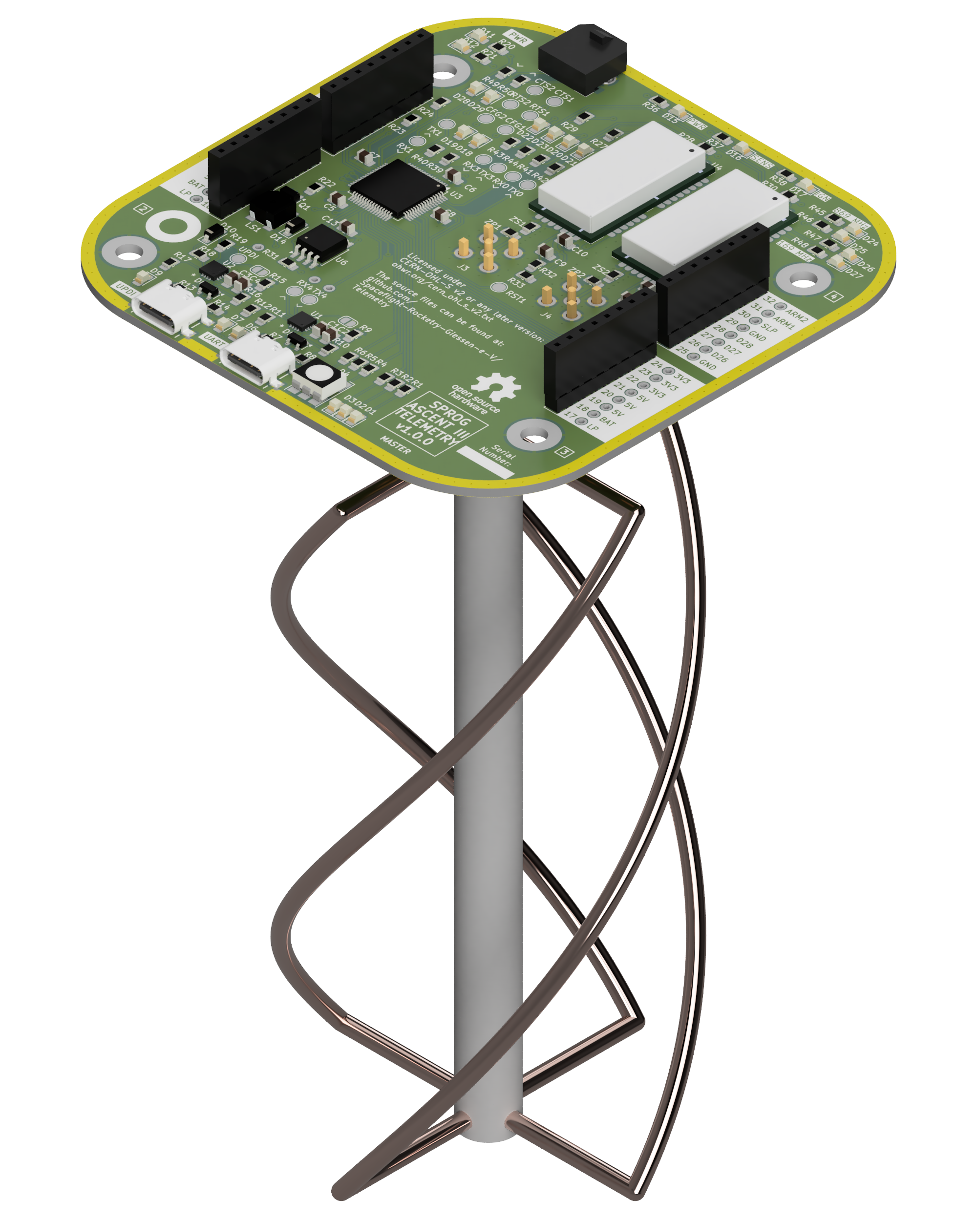
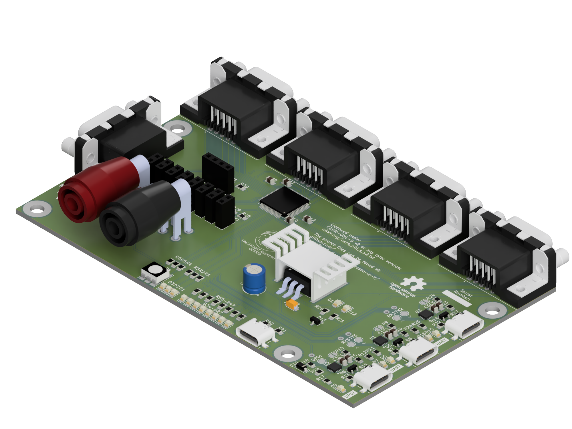
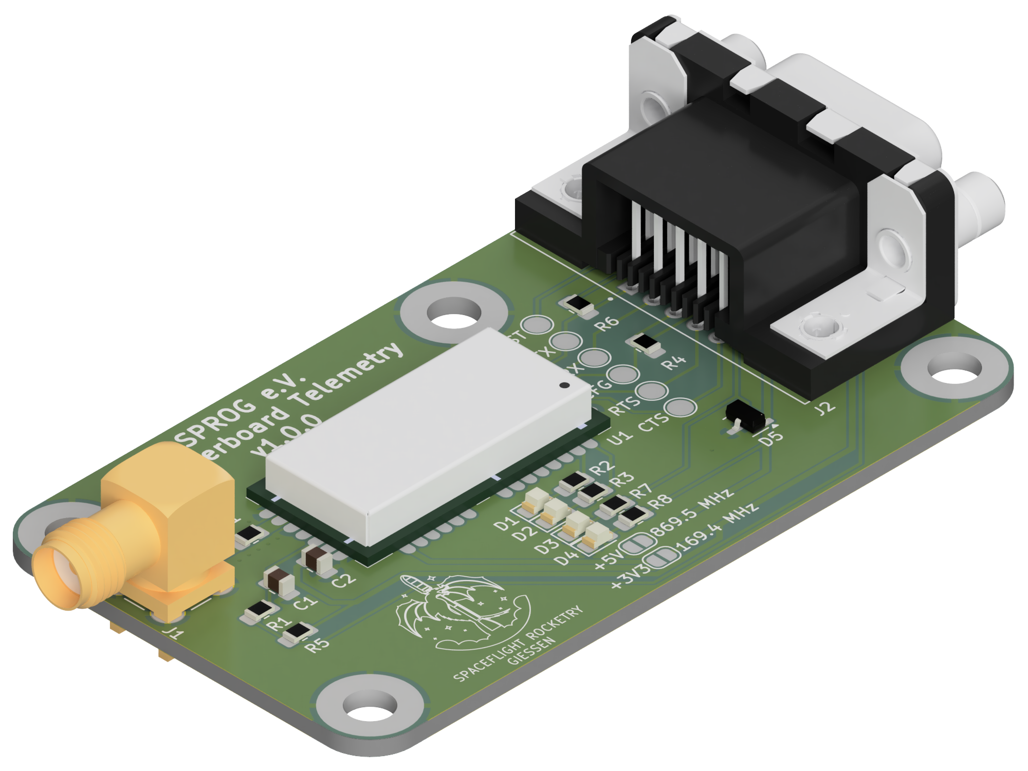
2 layers133 × 79.8 mm
TelemetryGroundstationMB
Spaceflight-Rocketry-Giessen-e-V/Telemetry
Open-Source Rocket Telemetry System Based On Radiocrafts RC232 Radio Modules
129 parts27CERN-OHL-S-2.0

 Spaceflight-Rocketry-Giessen-e-V/Telemetry27
Open-Source Rocket Telemetry System Based On Radiocrafts RC232 Radio Modules
TelemetryOnboard is an open-source printed circuit board by Spaceflight-Rocketry-Giessen-e-V, from the Spaceflight-Rocketry-Giessen-e-V/Telemetry repository on GitHub, published under the CERN-OHL-S-2.0 licence. It is a 4-layer board of 95 × 95 mm with 143 parts on 196 nets, routed with 631 tracks and 269 vias.
It is built around the CP2102N-EK, RC1701HP-RC232 and RC1780HP-RC232, with the W25Q80DVSSIG, RFPC-SMA28-F and SP0503BAHTG among its other parts. Its parts include 50 resistors, 29 diodes, 13 capacitors, 6 ICs and 5 connectors. It belongs with the radio and wireless boards of this library.


The ASCENT telemetry system is part of the ASCENT flight computer of the student rocketry club Spaceflight Rocketry Gießen e.V., which is being developed for the PIPE and ARCHER experimental rockets. This dual-frequency 169/869 MHz telemetry system based on Radiocrafts RC232 radio modules allows bidirectional data exchange between rockets and groundstations with a range of 20 km and a minimum data rate of 1.2 kbps. The design can easily be adapted for uses outside of rocketry like Smart Home or RC.

In January 2026, we performed our first long range test over a distance of 2 km. Despite poor weather conditions and objects inside the first Fresnel zone, the received signal strength was on par with the theoretical maximum without any unaccounted losses. This test ruled out major design flaws.
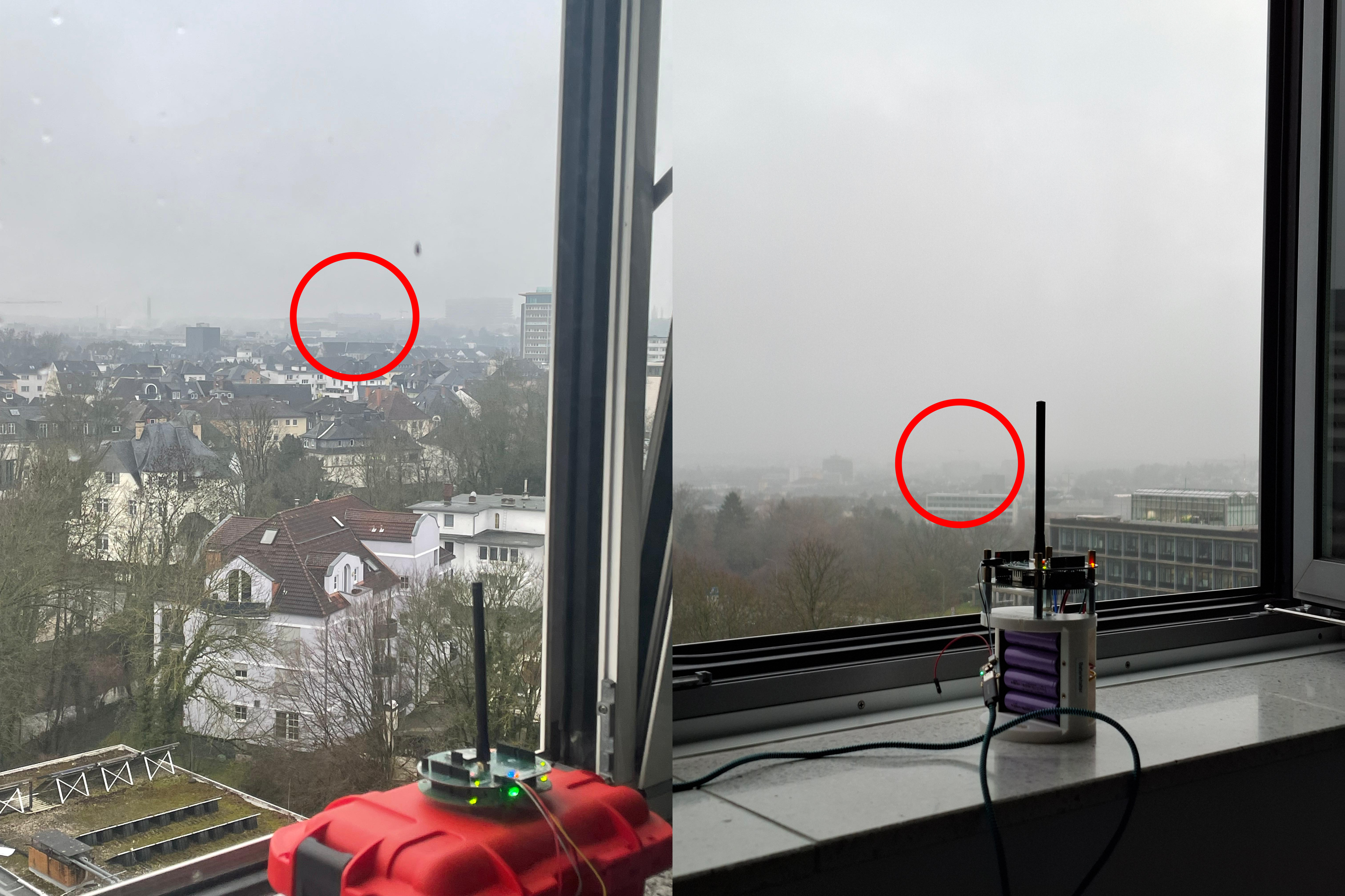
This excellent performance was confirmed by multiple medium range tests.
In April 2026, the system was successfully tested on the PIPE 2 rocket to an altitude of 350 m and experienced no link issues during the whole flight.
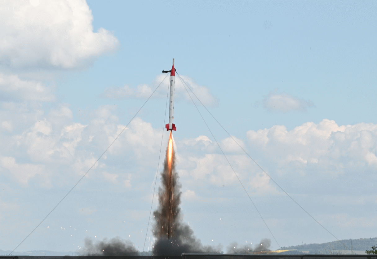
This repository contains all files necessary to reproduce the telemetry system, including hardware, firmware, software, and documentation.
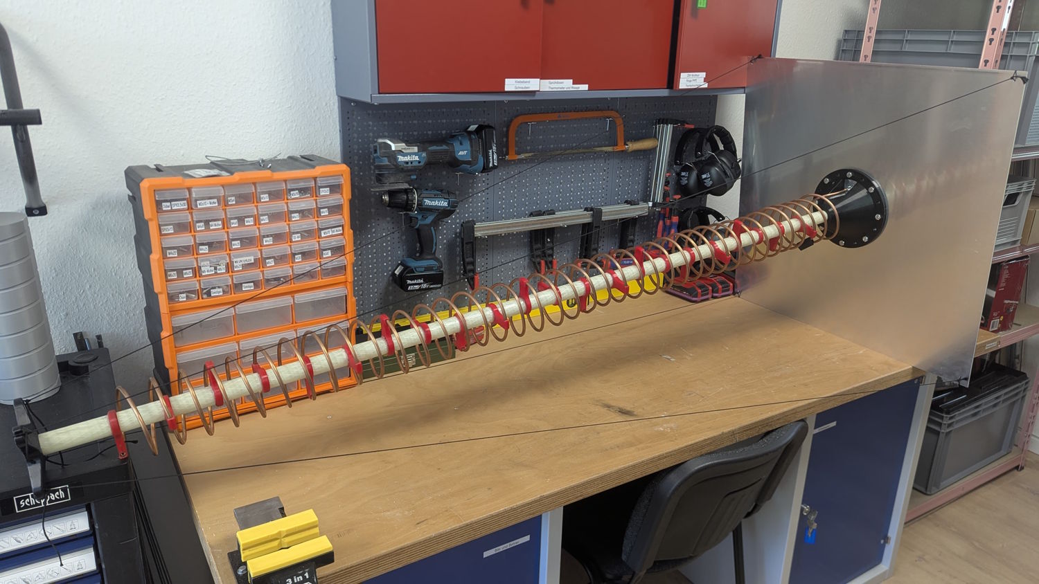
So far, this repository includes design files and assembly instructions for our helical 869 MHz groundstation antenna.
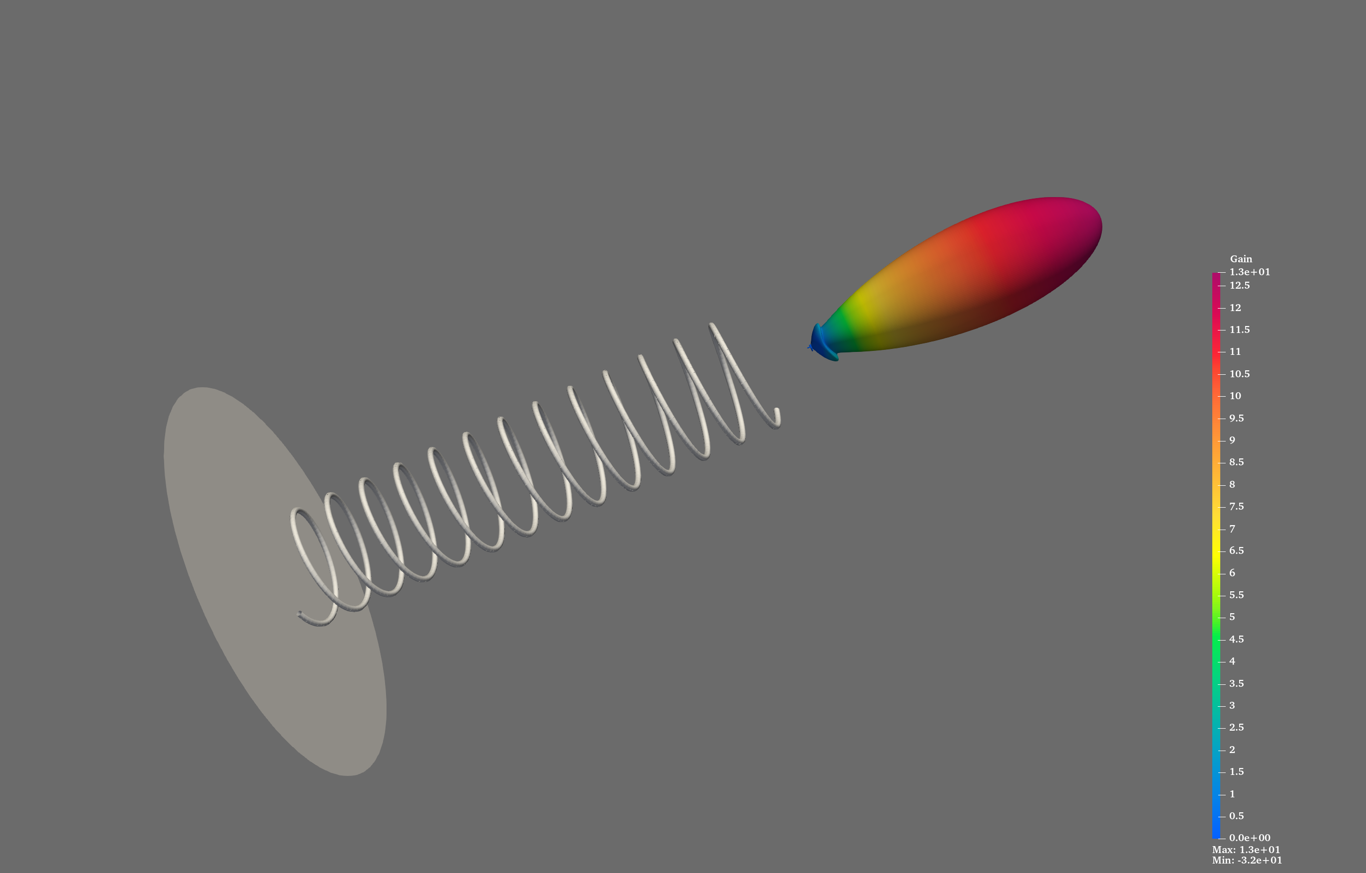
We also do our own FDTD-simulations which can be found here.
Currently, we are developing an 869 MHz QFH antenna.
The telemetry system is based on separate onboard and groundstation electronics. The groundstation uses a modular approach with a motherboard to which up to four daughterboards with radio modules can be connected.
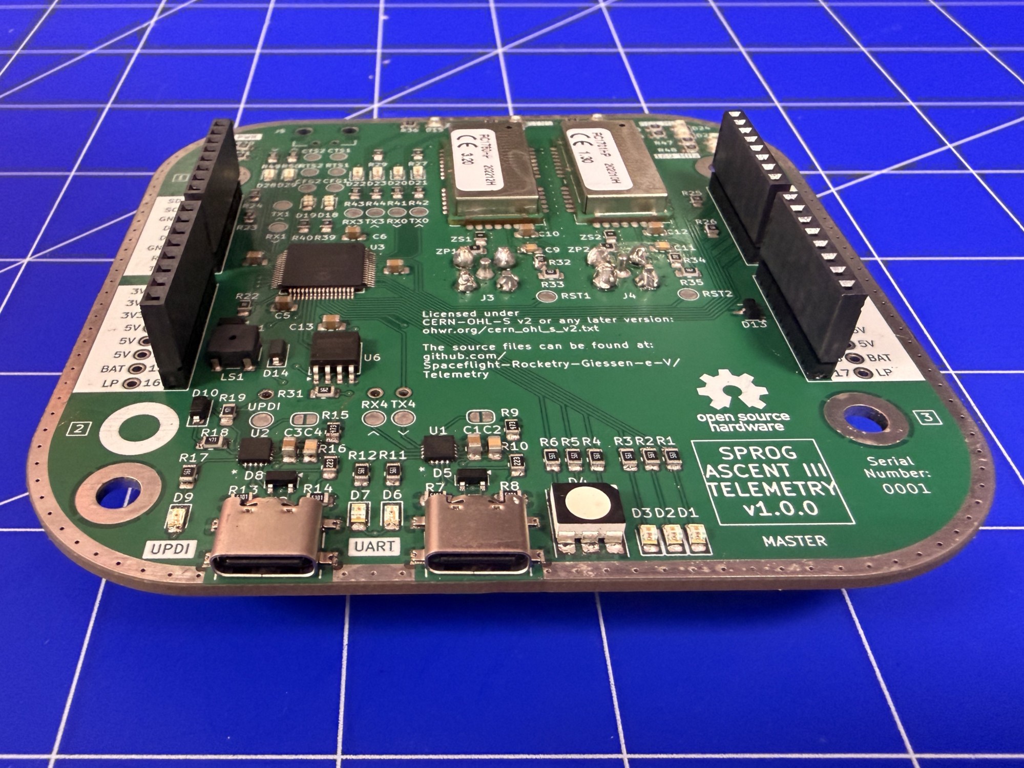
The repository includes for each system the KiCad design files including custom component schematic, footprint, and 3D model libraries, the PDF schematic, the Gerber production files, the bill of material (BOM) and an interactive BOM (iBOM). Renderings, images, and 3D models of the electronics are also included.
The onboard mounting structure, the motherboard and daughterboard casings are included separately.
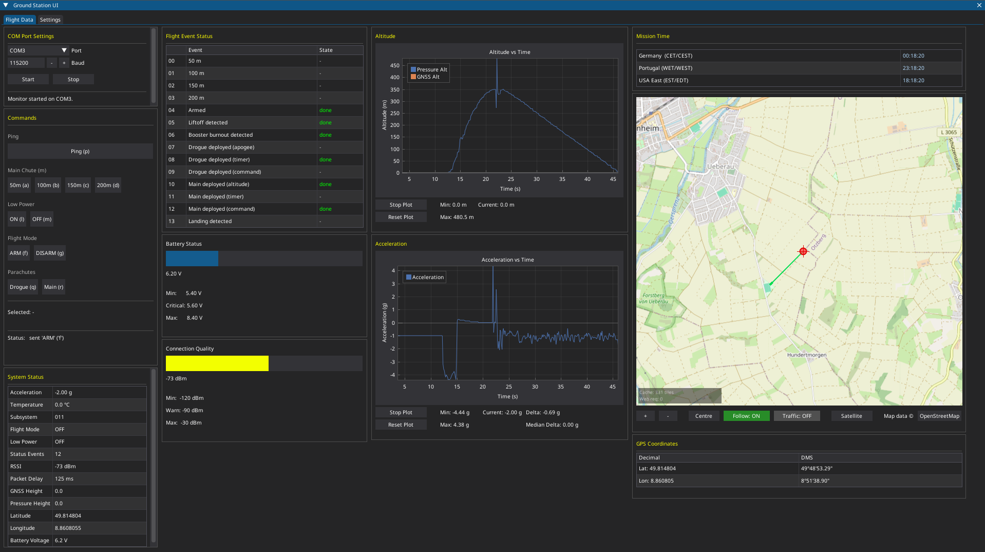
Python-based software to display live telemetry data on a modern, minimalistic interface with the ability to store flight data and send radio commands.
Widgets include a GNSS map view, a height plot over time, a acceleration plot over time, a battery voltage indicator with visual warnings, a connection quality indicator with visual warnings and a status event indicator.
Please note that radio systems may be subject to local regulations. Ensure that any testing or deployment of these systems complies with national and regional laws regarding RF transmission. The project maintainers are not responsible for misuse or regulatory violations.
Copyright Spaceflight Rocketry Giessen e.V. 2026
This source describes Open Hardware and is licensed under the CERN-OHL-S v2.
You may redistribute and modify this source and make products using it under the terms of the CERN-OHL-S v2 or any later version.
This source is distributed WITHOUT ANY EXPRESS OR IMPLIED WARRANTY, INCLUDING OF MERCHANTABILITY, SATISFACTORY QUALITY AND FITNESS FOR A PARTICULAR PURPOSE. Please see the CERN-OHL-S v2 for applicable conditions.
Source location: https://github.com/Spaceflight-Rocketry-Giessen-e-V/Telemetry
As per CERN-OHL-S v2 section 4, should you produce hardware based on this source, you must where practicable maintain the Source Location in its documentation or license information.
| Qty | Value | Footprint | References |
|---|---|---|---|
| 20 | 560R | Resistor_SMD:R_0805_2012Metric_Pad1.20x1.40mm_HandSolder | R1, R2, R3, R4, R11, R12, R17, R20, R21, R36, R37, R38, R39, R40, R45, R46 +4 |
| 17 | TestPoint | Footprints:Test Point | TP1, TP2, TP3, TP4, TP5, TP6, TP7, TP8, TP10, TP11, TP12, TP13, TP14, TP15, TP16, TP17 +1 |
| 11 | 5k6 | Resistor_SMD:R_0805_2012Metric_Pad1.20x1.40mm_HandSolder | R23, R24, R25, R26, R27, R28, R29, R30, R31, R33, R35 |
| 9 | orange | LED_SMD:LED_0805_2012Metric_Pad1.15x1.40mm_HandSolder | D1, D2, D3, D7, D15, D16, D17, D18, D19 |
| 7 | 1u | Capacitor_SMD:C_0805_2012Metric_Pad1.18x1.45mm_HandSolder | C5, C6, C7, C8, C10, C12, C13 |
| 7 | red | LED_SMD:LED_0805_2012Metric_Pad1.15x1.40mm_HandSolder | D9, D20, D21, D22, D23, D28, D29 |
| 6 | 1k | Resistor_SMD:R_0805_2012Metric_Pad1.20x1.40mm_HandSolder | R41, R42, R43, R44, R49, R50 |
| 5 | green | LED_SMD:LED_0805_2012Metric_Pad1.15x1.40mm_HandSolder | D6, D11, D12, D25, D27 |
| 4 | 5k1 | Resistor_SMD:R_0805_2012Metric_Pad1.20x1.40mm_HandSolder | R7, R8, R13, R14 |
| 4 | M4 Mounting Hole | Footprints:M4 Mounting Hole | M1, M2, M3, M4 |
| 4 | ~ | Resistor_SMD:R_0805_2012Metric_Pad1.20x1.40mm_HandSolder | ZP1, ZP2, ZS1, ZS2 |
| 2 | 0u1 | Capacitor_SMD:C_0805_2012Metric_Pad1.18x1.45mm_HandSolder | C2, C4 |
| 2 | 1n | Capacitor_SMD:C_0805_2012Metric_Pad1.18x1.45mm_HandSolder | C9, C11 |
| 2 | 22k | Resistor_SMD:R_0805_2012Metric_Pad1.20x1.40mm_HandSolder | R10, R16 |
| 2 | 2k7 | Resistor_SMD:R_0805_2012Metric_Pad1.20x1.40mm_HandSolder | R32, R34 |
| 2 | 470R | Resistor_SMD:R_0805_2012Metric_Pad1.20x1.40mm_HandSolder | R18, R19 |
| 2 | 47k | Resistor_SMD:R_0805_2012Metric_Pad1.20x1.40mm_HandSolder | R9, R15 |
| 2 | 4u7 | Capacitor_SMD:C_0805_2012Metric_Pad1.18x1.45mm_HandSolder | C1, C3 |
| 2 | CP2102N | Footprints:QFN20_CP2102N_SIL | U1, U2 |
| 2 | RFPC-SMA28-F | Footprints:RFPC-SMA28-F | J3, J4 |
| 2 | SP0503BAHTG | Package_TO_SOT_SMD:SOT-143 | D5, D8 |
| 2 | SolderJumper_2_Open | Footprints:Solder Jumper | JP1, JP2 |
| 2 | USB-C | Footprints:GCT_USB4216-03-A_REVA | J1, J2 |
| 2 | yellow | LED_SMD:LED_0805_2012Metric_Pad1.15x1.40mm_HandSolder | D24, D26 |
| 1 | 180R | Resistor_SMD:R_0805_2012Metric_Pad1.20x1.40mm_HandSolder | R22 |
| 1 | AVR128DB64x-xPT | Package_QFP:TQFP-64_10x10mm_P0.5mm | U3 |
| 1 | BAT43 | Diode_SMD:D_SOD-123 | D10 |
| 1 | CMT-0525-75-SMT-TR | Footprints:Buzzer XDCR_CMT-0525-75-SMT-TR | LS1 |
| 1 | Cree RGB LED | Footprints:Cree RGB LED | D4 |
| 1 | MMBT4401-TP | Package_TO_SOT_SMD:SOT-23 | Q1 |
| 1 | MMSD4148T1G | Diode_SMD:D_SOD-123 | D14 |
| 1 | Molex_MicroFit_2pin | Footprints:Molex_MicroFit_2pin | J5 |
| 1 | RC1701HP-RC232 | Footprints:Radiocrafts RC1780HP-RC232 | U5 |
| 1 | RC1780HP-RC232 | Footprints:Radiocrafts RC1780HP-RC232 | U4 |
| 1 | Stackable Socket 1x8 | Footprints:JL1 | JL1 |
| 1 | Stackable Socket 1x8 | Footprints:JL4 | JL4 |
| 1 | Stackable Socket 1x8 | Footprints:JL2 | JL2 |
| 1 | Stackable Socket 1x8 | Footprints:JL3 | JL3 |
| 1 | Stackable Socket 1x8 | Footprints:JR2 | JR2 |
| 1 | Stackable Socket 1x8 | Footprints:JR3 | JR3 |
| 1 | Stackable Socket 1x8 | Footprints:JR4 | JR4 |
| 1 | Stackable Socket 1x8 | Footprints:JR1 | JR1 |
| 1 | W25Q80DVSSIG | Package_SO:SOIC-8_5.3x5.3mm_P1.27mm | U6 |
| 1 | WE-TVS_SOT23-3L_824021 | Package_TO_SOT_SMD:SOT-23-3 | D13 |
The 140 most common of 143 parts.
Spaceflight-Rocketry-Giessen-e-V/Telemetry
Open-Source Rocket Telemetry System Based On Radiocrafts RC232 Radio Modules

Spaceflight-Rocketry-Giessen-e-V/Telemetry
Open-Source Rocket Telemetry System Based On Radiocrafts RC232 Radio Modules

Tinkerbug-Robotics/TinkerNav
RTK Rover and Base Station Firmware for TinkerNav Boards

icl-rocketry/Ricardo-PickleRick
A more compact Ricardo classic featuring a new sensor array, 4 pyro channels and 4 servo channels. Includes Ricardo bus plug too.


SaikoJuanma/phone_replacement
this projects aims to create a replacement for the phone, so I can stop using my phone on the home and get rid off distractions. ## Upcoming features 1. Timer and alarm. 2. PCB and schematics for the project. 3.


WRansohoff/CP2102N_simple
Simple breakout board for a CP2102N USB / UART bridge.
It measures 95 × 95 mm and has 4 copper layers, 1.6 mm thick.
143 parts, built around the CP2102N-EK, RC1701HP-RC232, RC1780HP-RC232 and W25Q80DVSSIG. The full list of its parts is on this page, with links to each part's symbol and footprint where PCBKit's library has them.
From the Spaceflight-Rocketry-Giessen-e-V/Telemetry repository on GitHub, at the commit this page was made from: the board is onboard/pcb/TelemetryOnboard.kicad_pcb and its schematic groundstation/pcb/Daughterboard/TelemetryGroundstationDB.kicad_sch. PCBKit opens the board in the browser, with nothing to install.
Its repository publishes it under the CERN-OHL-S-2.0 licence: you may reuse it on that licence's terms (keep the author's notice, and for a copyleft licence share your changes alike).