2 layers90 × 90 mm
PlasmaTransformer RF Node Igniter
inceptionev/PlasmaTransformer
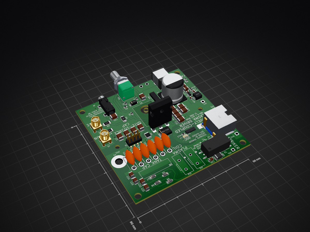
This project mainly focuses on creating a driver and 3D-printed support structure that allows for safe continuous operation of a plasma toroid.
65 parts14
 inceptionev/PlasmaTransformer14
This project mainly focuses on creating a driver and 3D-printed support structure that allows for safe continuous operation of a plasma toroid.
PlasmaTransformer is an open-source printed circuit board by inceptionev, from the inceptionev/PlasmaTransformer repository on GitHub. It is a 2-layer board of 90 × 90 mm with 86 parts on 40 nets, routed with 227 tracks and 32 vias.
It is built around the H8501-05, CC1812JKNPOCBN221 and VJ1812A102JXFTW1HV, with the 111122K01P00BQTAF9LM, CL32B475KCVZW6E and RFPC-SMA28-F among its other parts. Its parts include 30 capacitors, 21 connectors, 11 resistors, 7 diodes and 3 inductors.


This project mainly focuses on creating a driver and 3D-printed support structure that allows for safe continuous operation of a plasma toroid. The objectives are stable operation of a levitating halo of plasma at maximum height above the coil and protection against touching energized components, while providing airflow to keep both the electronics and the globe cool. The globes are filled with a low-pressure of xenon gas.
Special thanks to:
Sky-guided, whose inductive oscillation indicator design is used in this project.
@ltwin8, whose RF node parasitic auto-igniter design is used in this project and was detailed in https://github.com/inceptionev/PlasmaTransformer/issues/1
Native design files and manufacturing files in gerber and stl format are provided for the 20cm and 13cm globe sizes.

KiCAD PCB files are found in the /Plasma Transformer PCB folder. If you want to edit the design, the files are in the folder. If you just want to make the boards, you need:
Rev 5 PCB specific note: The holes for the capacitor sockets are too large, so instead of being press-fit, they will need to be soldered in. I recommend using a piece of paper tape to hold them in place on the top side, then soldering them on the bottom side. Or you can skip the sockets and solder in the capacitors directly.
3d print design files and a dxf for the heatsink hole pattern are found in the 3D Print and CNC folder. The heatsink holes are all M3 drill/tap.
If you are doing turnkey PCBA assembly, you probably want to DNP the fan (M1), heatsink (HS1), MOSFET (Q1), and tank capacitors (C1, C16-20) from the BOM in the Turnkey Assembly ZIP package, as you will assemble these later.

If you just want to print the files, look here:
Supply Voltage:
Gate-Drain Cap:
Resonant Cap:
Gate-Source Cap:
Measured Air Core Inductance of Globe Coils (no globe or plasma present):
| Qty | Value | Footprint | References |
|---|---|---|---|
| 12 | Conn_01x01_Socket | AFootprints:H8501-05 | J7, J9, J10, J13, J14, J15, J16, J17, J18, J19, J20, J21 |
| 6 | 24pF | Capacitor_THT:C_Disc_D11.0mm_W5.0mm_P10.00mm | C1, C16, C17, C18, C19, C20 |
| 4 | 220pF | Capacitor_SMD:C_1812_4532Metric | C7, C8, C9, C10 |
| 4 | D | Diode_SMD:D_SMF | D5, D6, D7, D8 |
| 3 | 1.8nF | Capacitor_SMD:C_1812_4532Metric | C4, C5, C6 |
| 3 | 1k | Resistor_SMD:R_0805_2012Metric | R2, R4, R5 |
| 3 | 1nF | Capacitor_SMD:C_1812_4532Metric | C11, C12, C21 |
| 3 | 1pF | Capacitor_SMD:C_1210_3225Metric | C14, C15, C22 |
| 2 | 100nF | Capacitor_SMD:C_0805_2012Metric | C27, C28 |
| 2 | 4.7uF | Capacitor_SMD:C_1210_3225Metric | C25, C26 |
| 2 | 499 | Resistor_SMD:R_2010_5025Metric | R7, R8 |
| 2 | Choke | Connector_Wire:SolderWire-1sqmm_1x01_D1.4mm_OD2.7mm | TP2, TP3 |
| 2 | Conn_02x04_Odd_Even | Connector_PinHeader_2.54mm:PinHeader_2x04_P2.54mm_Vertical_SMD | J4, J6 |
| 2 | Conn_Coaxial | ALibrary:SMA_Amphenol_901-144_Vertical | J3, J5 |
| 2 | Screw_Terminal_01x01 | ALibrary:CONN_2604-3101_WAG | J11, J12 |
| 1 | 0 | Resistor_SMD:R_1812_4532Metric | R6 |
| 1 | 100k | Resistor_SMD:R_0805_2012Metric | R1 |
| 1 | 100nF | Capacitor_SMD:C_1812_4532Metric | C13 |
| 1 | 10V Zener | Diode_SMD:D_SMA | D1 |
| 1 | 10uF | Capacitor_SMD:C_0805_2012Metric | C30 |
| 1 | 15V TVS | Diode_SMD:D_SMC | D2 |
| 1 | 1k | ALibrary:Bourns-Potentiometer-PTD902-2 | RV1 |
| 1 | 2.7nF | Capacitor_SMD:C_1812_4532Metric | C3 |
| 1 | 2.7pF | Capacitor_SMD:C_1210_3225Metric | C23 |
| 1 | 22uF | Capacitor_SMD:C_0805_2012Metric | C29 |
| 1 | 22uH | ALibrary:L_Pana_PCC-KVP_5.5x5mm | L3 |
| 1 | 300V GDT | Inductor_SMD:L_1812_4532Metric | GD1 |
| 1 | 30uH | ALibrary:B82559B_TDK | L2 |
| 1 | 330uF | ALibrary:CP_Elec_16x17.5_FK_Series | C2 |
| 1 | 3k | Resistor_SMD:R_0805_2012Metric | R3 |
| 1 | 47nF | Capacitor_SMD:C_1206_3216Metric | C24 |
| 1 | 49.9 | Resistor_SMD:R_2010_5025Metric | R9 |
| 1 | 680 | Resistor_SMD:R_0805_2012Metric | R13 |
| 1 | 7.15k | Resistor_SMD:R_0805_2012Metric | R10 |
| 1 | AMBER | LED_SMD:LED_1206_3216Metric | D3 |
| 1 | AudioJack3 | ALibrary:Jack_3.5mm_CUI_SJ-3523-SMT_Horizontal | J8 |
| 1 | BO-02 | ALibrary:BO-02 | T1 |
| 1 | Barrel_Jack_MountingPin | Connector_BarrelJack:BarrelJack_CUI_PJ-063AH_Horizontal | J1 |
| 1 | Conn_01x02_Pin | Connector_JST:JST_XH_B2B-XH-A_1x02_P2.50mm_Vertical | J2 |
| 1 | Fan | Library:FAN AXIAL 92X25.4MM | M1 |
| 1 | Heatsink | Library:Heatsink_75x37.5mm_Fischer_SK-594-37.5-AL | HS1 |
| 1 | Hole_Heatsink_Screw | MountingHole:MountingHole_8.4mm_M8 | H2 |
| 1 | Ignition Wire | Connector_Wire:SolderWire-0.75sqmm_1x01_D1.25mm_OD2.3mm | TP1 |
| 1 | LMR51610YDBVR | Package_TO_SOT_SMD:SOT-23-6 | U1 |
| 1 | PCB Coil | Library:FEEDBACK_COIL_B | L1 |
| 1 | Pad_Doorknob_Cap | MountingHole:MountingHole_5.3mm_M5_Pad | H1 |
| 1 | Q_NMOS_Depletion_GDS | Package_TO_SOT_THT:TO-247-3_Horizontal_TabDown | Q1 |
| 1 | SW_SPDT | ALibrary:CKSW-E101J1AV2QE2 | SW1 |
| 1 | ZS 1052-S HT(H) | ALibrary:ZS 1052-S HT(H) | T2 |
inceptionev/PlasmaTransformer
This project mainly focuses on creating a driver and 3D-printed support structure that allows for safe continuous operation of a plasma toroid.

inceptionev/PlasmaTransformer
This project mainly focuses on creating a driver and 3D-printed support structure that allows for safe continuous operation of a plasma toroid.

inceptionev/PlasmaTransformer
This project mainly focuses on creating a driver and 3D-printed support structure that allows for safe continuous operation of a plasma toroid.


Neotron-Compute/Neotron-Common-Hardware
Contains KiCad footprints and symbols shared across multiple Neotron projects.


oresat/oresat-battery-testing
Battery testing software and circuitry for testing cells and batteries to fly on the ISS


ChromiumOS-Guy/ZVS-Driver
A ZVS Driver (1-Layer) PCB I Designed so I can use a PCB instead of making a mess of wires

omerikinci/ELV1
Elektronik kör yük (electronic dummy load) cihazının ilk stabil versiyonu. 150 W ile sınırlandırılmış, 30 V / 10 A aralığını destekler.

ihsan-sa/High-Power-DC-DC-Converter
A DC-DC converter for high-power (>750W) adjustable output.
It measures 90 × 90 mm and has 2 copper layers, 1.6 mm thick.
86 parts, built around the H8501-05, CC1812JKNPOCBN221, VJ1812A102JXFTW1HV and 111122K01P00BQTAF9LM. The full list of its parts is on this page, with links to each part's symbol and footprint where PCBKit's library has them.
From the inceptionev/PlasmaTransformer repository on GitHub, at the commit this page was made from: the board is Plasma Transformer PCB/PlasmaTransformer.kicad_pcb and its schematic Plasma Transformer PCB/PlasmaTransformer.kicad_sch. PCBKit opens the board in the browser, with nothing to install.
Its repository states no licence, so its author keeps all rights: ask inceptionev before reusing the design.