
4 layers50 × 50 mm
LaserDriverRGB
Rivercraft911/R-01_Raster_Laser_Projector
Red, blue and green lasers combine through two dichroc mirrors and bounce off a spinning polygon mirror, which each mirror facet makes one scanline.
76 parts1

Red, blue and green lasers combine through two dichroc mirrors and bounce off a spinning polygon mirror, which each mirror facet makes one scanline.
Pcb AMY is an open-source printed circuit board by Rivercraft911, from the Rivercraft911/R-01_Raster_Laser_Projector repository on GitHub. It is a 4-layer board of 100 × 100 mm with 159 parts on 100 nets, routed with 883 tracks and 155 vias.
It is built around the TPS54360DDA, OPA1656ID and TPS55340PWP, with the TPS60400DBV, TXS0102DCU and B560C-13-F-MS among its other parts. Its parts include 62 capacitors, 42 resistors, 15 connectors, 10 ICs and 6 inductors.


A RGB raster laser raster projector, Postmortemly known as Icarus :(
TODO: ADD RL PHOTO HERE
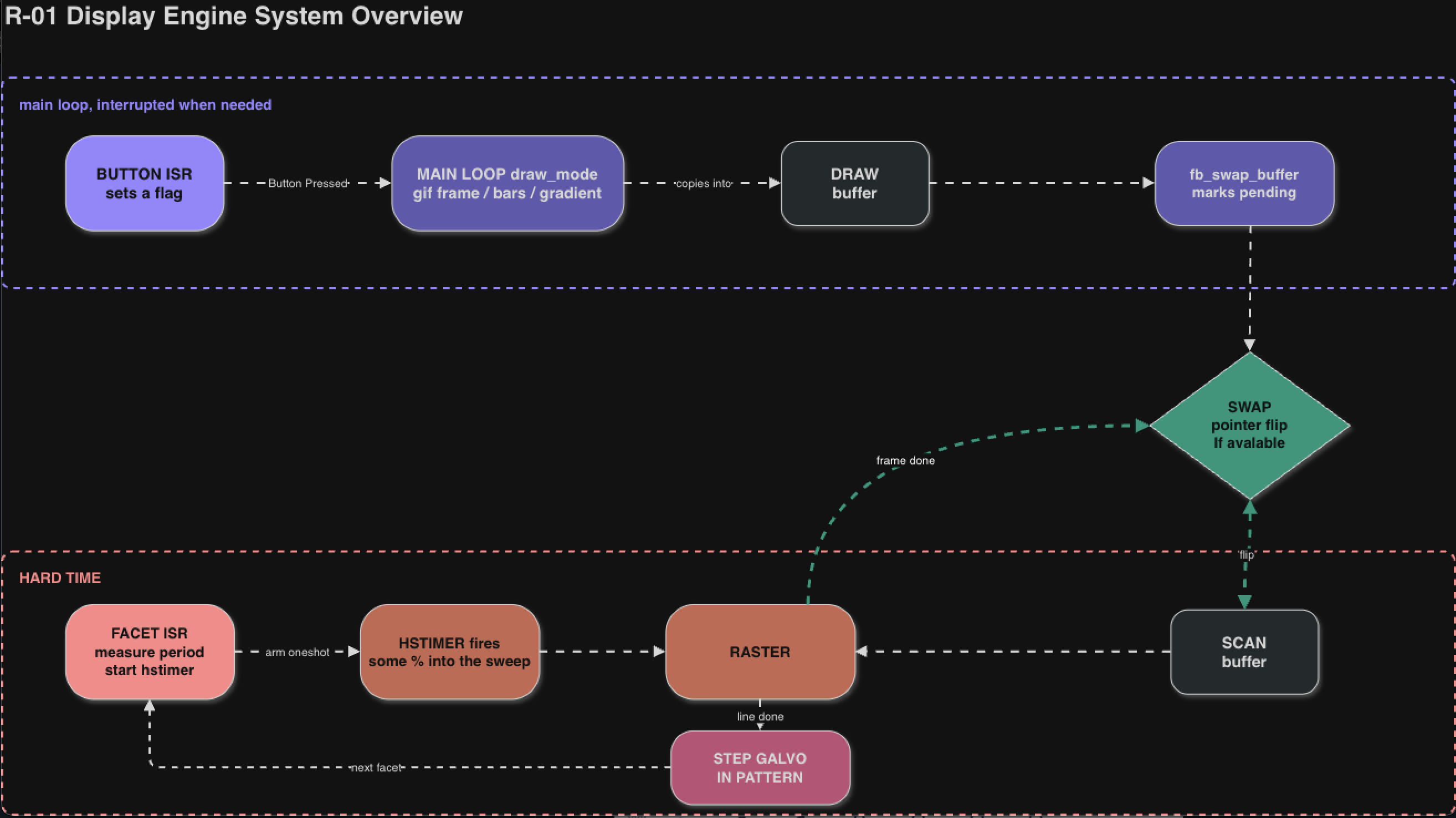
Red, blue and green lasers combine through two dichroc mirrors and bounce off a spinning polygon mirror, which each mirror facet makes one scanline. An IR sensor watches the facets go by and fires an interrupt, we measure how fast the mirror is spinning and then arm a timer to start the raster when on screen. Timer goes off and we bitbang 320 pixels out the GPIO ports, then move the galvo in a specific pattern and do it 120 times. At the top of every frame we then swap framebuffers
Color works through each laser having four driver channels with binary weighted currents, the enable pins give the brightness per color channel.
-shift -rangefinder for autofocus would be crazy
River Amy
firmware/         all the MangoPi Code
-main.c         It's main... In a perfect world projects premade things
-raster.c       the thing actually placing pixels out the gpio ports
-sync.c         the two isrs that lock painting to the mirrors spin
-framebuffer.c  double framebuffer
-galvo.c        vertical mirror over spi
-config.c       laser current dac codes + the color palette
-overclock.c    we be overclocking NOT WRITTEN FOR FINAL PROJECT, wrote before for lab
-pins.h         the one and only true pin map
-ypes.h        shared sizes and types that are in use for
-test.c         ringup tests + general tests
-gifs.h          animation frames, generated by a tool not written by me tools/gif2c.py
pcbs/            kicad PCB files for both boards(LaserBrain + LaserDriverRGB)
docs/            proposal and datasheets
tools/           python tools
chassis_cutouts/ lasercut panel files
images/          photos n such
This software was super fun to figure out and write! It was all bounded by one thing. The spinning polygon mirror. Every piece of the actually projecting part of the code had to be constantly measure and resync to the mirror.
A frame works like this: the IR sensor sees a facet go by(have another one physically that could be used to resync the current facet IR sensor but the SW is not written yet), an ISR then clocks how the mirror period. Then a HGtimer is set for the exact moment the beam should hit the screen. When we reach that moment the ISR constantly writes to the EN pins to output 320 pixels, each one pixel then sent to its own absolute timestamp so jitter never gets a chance to accumulate, which hopefully would solve a big problem other peoples projectors faced online. Then it goes blank, step the galvo along an interlacing patturn(odds down, evens back up) so the galvo never does a big jump(this idea came from yt project), and the framebuffers then swap at the top.
Quick aside because there were so many ideas that never made it in. Julie suggested computing exact interrupt for each and every pixel timing instead of my spin wait (thank you Julie!) and I never had time to try implementing it and test speeds and such to see if that one would cook. At one point the plan also had a 32KB nearest-color table for full RGB input, uart streaming where the newest frame wins, and the dead 70% of every facet sweep was gonna run DOOM. I also have a theory that with just a SW update one could actually get full 12-bit color. By using the 4 channels per color and building a queue of color values for the next few pixels in advance, one could use the much slower analog CC swap and just enable one channel at a time, I would need to test how fast a changing CC stabilizes, and you might need something more like 16 channels per color to make this work, I plan to test it soon though... Alsoo all of the non Raster/Painting stuff was meant to be DMAd but I ran out of time figure all of that out when the HW started failing.
Color is one byte per pixel(rrrgggbb) and all of the the math happens at bootup every one of the 256 values precomputes into 4 gpio port words, so then painting a pixel is then only one table lookup where we do 4 writes(if I was more locked in during the HW design phase I could have made this 1. Oh well. rev 2 I suppose). No color math, no branches, nothing. Thats how the loop went from 637khz to 1.83MHz(full speed arc below)
R-01's hardware is filled will all sorts of fun and terrifying things. From lasers that have now set walls on fire, to ICs set aflame, many a cortisol spike have occurred throughout the design and development. Here is a general overview of it all:
Our custom HW:
LaserBrain:
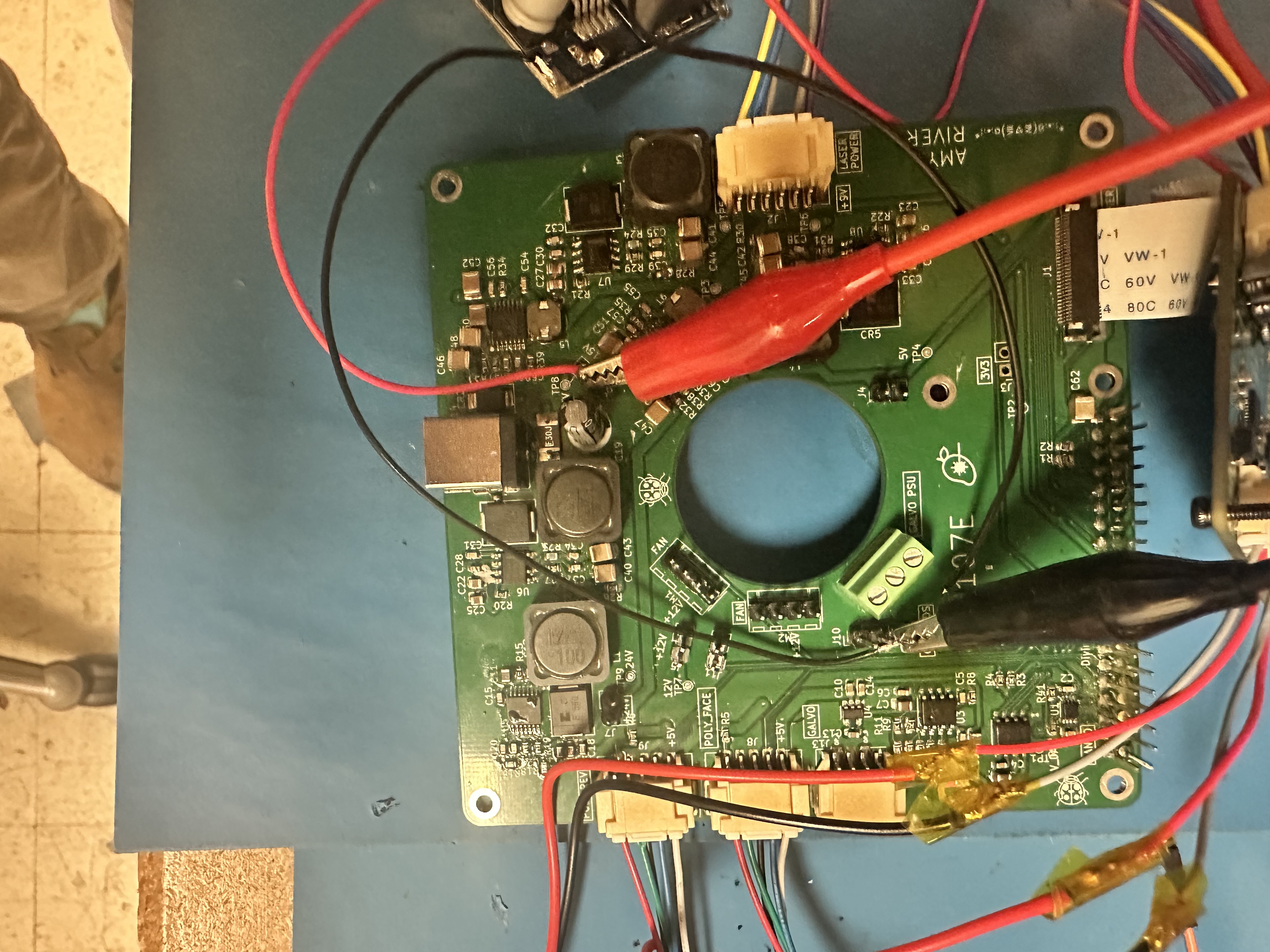
This board serves as a hat for the MangoPi and this board handles all the interfacing with outside hardware! It features
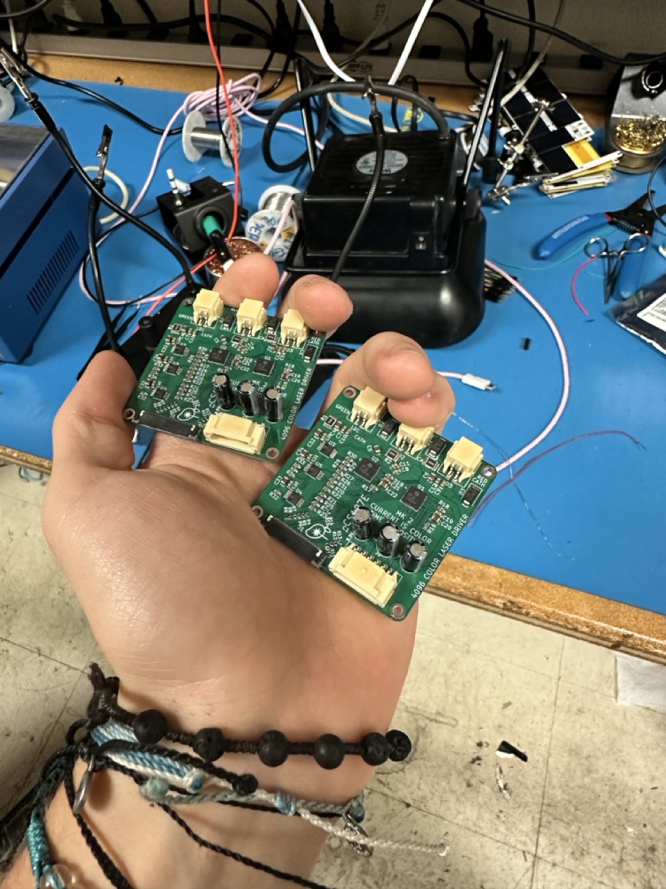
LaserDriver: This board is where we controll all of the lasers! It also can be used for a lot more than this project if needed. It can support up to 1A lasers...
GALVOs: Just the cheap modules on Aliexpress, can do 20Kpps. Link: https://shorturl.at/cWeSp
Laser Polygon: Taken off of many a printer.
Hardware Difficulties:
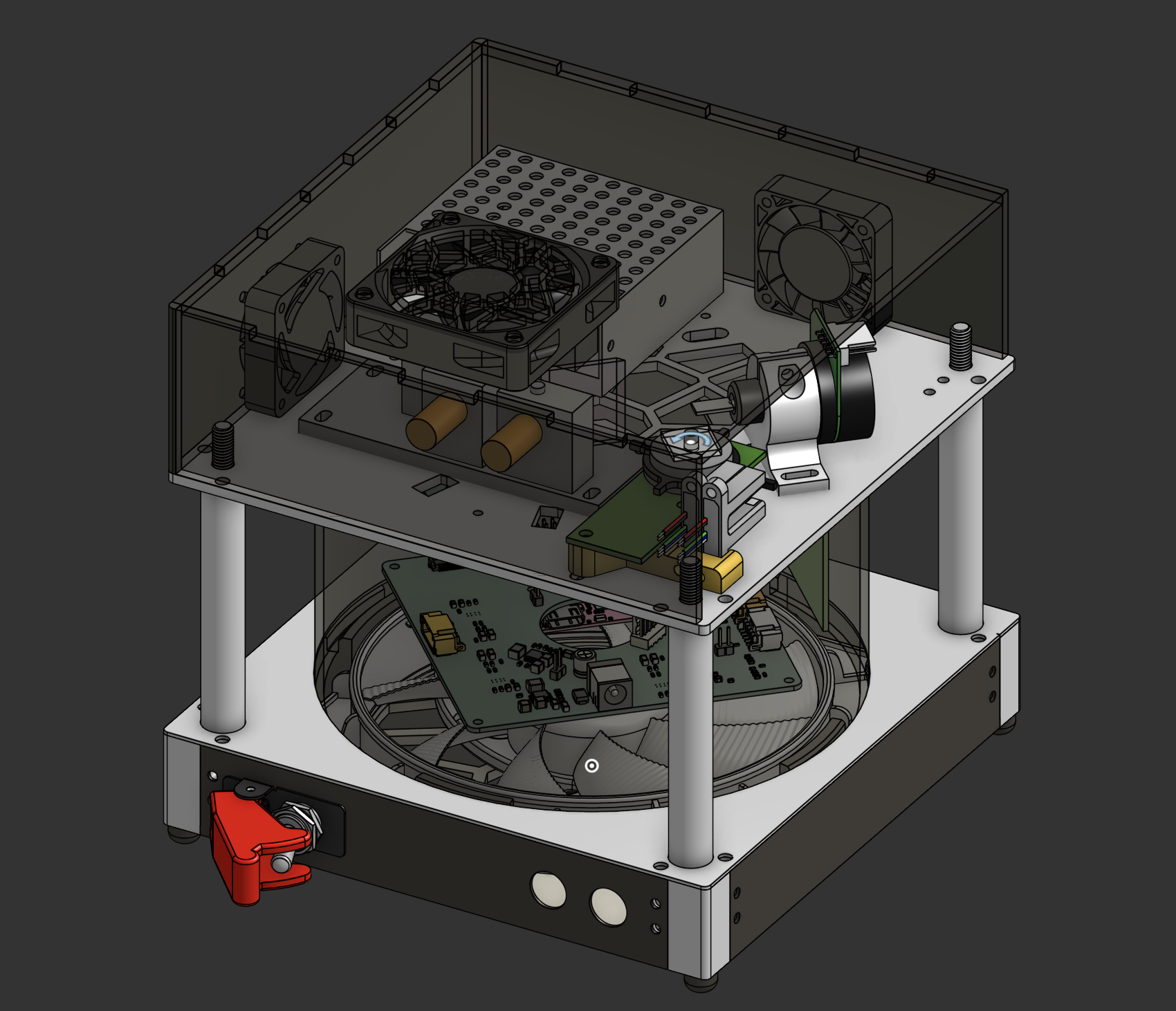 R-01's structure is state-of-the-art. And by that I mean it's more befitting of an art gallery than a place that features good engineering. Jkjk, but here is the rundown:
19 custom distinct parts (Lasercut + 3D printed)
129 total parts (including fasteners and duplicates, grabbed from the CAD so give or take a few)
1/8in Aluminum Base and Top plate (This is important for the several-watt laser and galvo thermals!)
Two Dichroic Mirrors for beam combining.
All 3D printed PTFE adjustable mounts for optics
Tinted Acrylic Lid to save the eyes from the lasers.
Parametric CAD design where everything is a variable so changing anything about the design is super easy
4 PWM fans with a huge tube air duct that blows over all the boards for cooling
Fun Covered ToggleSwitch + Keyswitch for safety and looks
Laser Engraved Sideplate
A ton of little measurements and configs and just lining up reality with the software was needed to try to get this thing running. Some of them were neat and required quite a bit of work so I figured I would throw them in here. First we had to do some simple math which informed a lot of our design, on both the SW and hardware side. We were targeting 15fps and a 320x120 screen. The beam is only on the screen for the middle ~30% of each facet sweep. So: 15 fps x 120 lines = 1800 lines(facets) per second 1800 facets/s / 4 facets = 450 rev/s = need 27,000 RPM on the polygon 320 pixels in 30% of a 555us facet period = 1.92 MHz pixel rate
At first we were not making this pixel rate with our OG read modify write loop so we had to get quicker: The OG loop was doing a read modify write on all 4 gpio ports for every pixel, and reads were cooking us. We ended up grabbing each port's background bits once per entire written line(OPL), the inner loop is a palette lookup and 4 writes. That plus overclocking the DDR +20% and the CPU to 1608MHz lended us:
| version | pixel rate | fps it buys |
|---|---|---|
| read-modify-write, stock clocks | 637 khz | ~5 fps |
| read-OPL + DDR +20% + CPU 1608MHz | 1830 khz | ~14.3 fps |
(measured with test_speed in test.c: 32000 real palette writes through the real inner loop, where we then timed with timer_get_ticks) In the current state 1830 khz is slightly below of the full 1.92 MHz target, but the window and screen size could all be adjusted if we needed to. TODO: FINISH YAP ABOUT GALVO CALS galvo is rated 20Kpps, we should only need 1800 steps/s
The most current thing im dealing with is this git tomfoolery: remote: Resolving deltas: 100% (29/29), completed with 17 local objects. remote: error: File firmware/gif_bad_apple.h is 281.88 MB; this exceeds GitHub's file size limit of 100.00 MB remote: error: GH001: Large files detected. You may want to try Git Large File Storage - https://git-lfs.github.com
In general, though, the project is stuck in what I feared, integration. I spent a few hours today doing some more methodological hardware debugging and am working on a few more bring-up tests. I know I should be one or two bugs away from this thing springing to life. I also found a lot of small HW issues hiding around and discovered why the Polygon motor burnt to a crisp.
I plan to finish it up this summer! Especially since there are tons of EE and embedded CS honkers at my company, so I can ask for help. Besides just figuring out some of the current poly motor failure points and the random times that I2C stops working, and why the galvo is not responding. I want to try to see through some more of the OG vision. Such as all non blocking DMA calls when not printing, and doing timing more elegantly.
In the far future, I plan to lock in on R-02 with many, many upgrades, not for pure performance but for ease of use and elegance. Shift registers, NOT A RIBBON CABLE BETWEEN BOARDS, more debugability and testpoints, and more are noted, and as I carefully debug everything, I expect that list to grow precipitously.
River - Software design and implementation, Mechanical design and assembly, Laser driver board, Routing and schematic work on main LaserBrainboard, making bad architectural decisions.
Amy - Laserbrain Board scematic and layout, PDU, Harnessing, Lasercutting out strucural panels, 6.5V rail debugging, Board component speccing/ordering, Proposal TODO: FNISH
These peoples projects are what gave the idea + were a great help:
https://hannahmishin.com/blog/2014/10/25/laser-scanner-cameraprojector This one was great and went very in depth to their process, which took a fun winding route from camera to projector.
https://www.youtube.com/watch?v=fEPicBSYeNQ&t=742s This one was very similar to our design!
https://www.hackster.io/felix-missel/laser-projector-98aa03
This one was a laser vector display with just galvos. In hindsight this would have been a better and more feasible project. (the galvos never worked though so maybe not) https://www.youtube.com/watch?v=bdo3djJrw9o&t=316s
Carson Laurer + Ayush Gaarg helped refine the SW architecture Julie with timing help! I never got to implement/test the intruputs with exact timestaps that way though since the HW was not working. HOWEVER, the exact timing bit from that is great and is in use rn! It solves several things including jitter!
AI REFERENCES: claude for the gif2c.py file. This file never got to the point of actually being in use sadly. It converted gifs and images to 8-bit color and outputted them as usable FBs
claude also wrote palette_from_rgb444 in config.c(cited inline), the function that packs 4-bit rgb(our theoretical color amount) into precomputed gpio port words for the palette. I ran out of time to work that one out myself during the push for color. In hindsight I should have just went to the pinout diagram and written it. Or truly in higntsight, I should have been spending that time debugging Galvo motors.
I also looked at some random Stack Overflow Qs occasionally, as well as other sites, but usually, if I actually used anything rather than just learning, I cited those at the top of the file!!
How well was your team able to execute on the plan in your proposal?
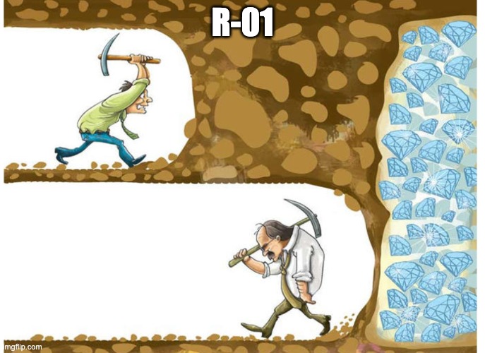
Both motor drivers, the optical sync interrupts (verified before the hardware existed by jumpering a PWM pin over as a fake facet sensor), and we dropped the proposal's nearest-color table for something simpler and arguably a bit more elegant, a uniform palette where the index is the color. The hardware is where the plan died: the polygon caught fire, the galvo never moved, so no scanlines. The sad and ironic part is our written backup for "polygon doesnt work" was to fall back to galvo only graphics and the galvo was the other thing that never worked. Overall though the software is at a very "complete" state and perhaps I am that minecraft miner but I am so sure with just a bit more debugging hardware and software bugs we can reach text raster.
(SORRY IF I TALKED FOR TOO LONG) I can confidently say I learned more from this project than from any other project I have ever worked on. I feel like I could talk for hours about any aspect of it. It truly challenged everything in my skill set with the design and architecture of fun software, electrical engineering, and mechanical engineering. I think I may have had the possibility of getting more CS out of it if we went with a less interdisciplinary project, but the tandem nature of it helped me understand so so so much about making designs in both HW and SW that inform and help one another + coming up with fun HW ways to test software before having the actual hardware done(connecting PWM gpios with wires to test interrupts and painting and so on). I shot myself in the foot a bunch when doing hardware prep that a current me now knows not to tread(thinking about you GPIOs, DMA shift reg and more, ribbon oh ribbon).
On the mechanical side, I learned all sorts of things when it comes to designing better parametric CAD as well as better ways to manufacture things. I am never going back to a life before heat-set inserts on my 3D printed parts. So many annoying bits, from things never lining up. Bolts are larger than I thought. Ordering the wrong size aluminum. My design process for larger assemblies has gotten a lot better.(I definitely made a big mistake and got a bit too carried away with the design and really should have spent those hours just doing more debugging boards.)
For EE, this was the fastest we have ever had to design, test, and order boards. For those first few nights, I slept nill as all of the boards needed to be ordered in time to come in from China + time to bringup and fix any flaws(which existed in number). Also, OMG, the amount of random power rails we needed for this amalgamation of parts got very out of hand. The laser driver board was also the first "hard/interesting" PCB I have gotten the chance to design, as it actually had some concerning things to worry about (partially actually caring about parasitics and transients)
For Software, I hold the belief that I somehow learned more than the class on this project. I guess not really learned more information, but actually understood a lot more, as, for once, the modules were not handed to me on a silver platter. When I had to fully architect the modules and write the header files was where those important neural pathways truly came into fruition, and I started to feel like I was “getting” it? I mean, I think I went back to the assignments like a billion times to read over old code(mainly y’alls) and how those were planned out for inspiration. Then I had to figure out which of those patterns actually worked with my problem and which didn't, and when they didn’t, struggle like a magikarp out of water. I am very proud of how the system is formatted, even though I don't particularly love a lot of the implementation and the blocking nature of everything in the current state. I really like how the ISR side of things and the main loop world are separated by exactly one volatile flag. I am pretty proud of doing a bunch of research and hand calculations for what I needed the software to be capable of and then optimizing until we got there. I started thinking a lot more about time budgets, what's the cost of a read vs a write, with writes being more than I realized at first. The timestamps being absolute is super fun to me, with it solving a plethora of problems like error compounding over time and the jitter you see on some of the ones online!
I also tried very hard to follow what my belief of good style to be, on both the EE end and CS end. Not so much MechE… I am still not that sure about good CAD style, but I tried.
Everything is very distributed and modular, in my mind quite testable; it took me quite a bit to get the test.c cooking, but once I did it was almost therapeutic to spend hours on Saleale logic checking code and fixing things up.
I could probably keep the reflective rambling sesh going forever and ever, but TLDR: I LEARNED A TON! and I am super super sad I couldn't produce a good demo. Moping for days, however, I am not one to stay down in the barrows for too long and am looking forward to finishing this up and dropping the summer Ed post with this thing locked in. By next fall, mark my words, Hoover tower will contain a massive green glowing “107E Rocks!” projection.
Collection of the first few that comes to mind. many many more silly things were lurking that did not make the short cut.
Hello! Here are some photos and videos of our dear R-01 in action. You can see the Poly spin test and the blink test with one laser! I also on sunday when I come back to campus can get a picture/ video of trying out different color combos!
https://github.com/user-attachments/assets/df00af2f-085e-4b30-8c3d-586970411df2
https://github.com/user-attachments/assets/c5193d83-9ada-4097-a43f-31f74a566e26
TODO: COLOR VIDEO AND MAYBE TRY GET GALVO WORK
| Qty | Value | Footprint | References |
|---|---|---|---|
| 18 | 0.1uF | Capacitor_SMD:C_0603_1608Metric | C1, C2, C4, C5, C12, C20, C28, C29, C30, C31, C32, C33, C54, C55, C56, C57 +2 |
| 15 | 10k | Resistor_SMD:R_0603_1608Metric | R3, R4, R8, R9, R10, R11, R18, R27, R29, R31, R34, R35, R38, R41, R42 |
| 11 | 22uF | Capacitor_SMD:C_1206_3216Metric | C40, C41, C42, C43, C44, C45, C46, C47, C48, C49, C62 |
| 8 | TestPoint | TestPoint:TestPoint_Pad_D1.0mm | TP2, TP3, TP4, TP5, TP6, TP7, TP8, TP9 |
| 7 | MountingHole_Pad | MountingHole:MountingHole_2.7mm_M2.5_DIN965_Pad | H1, H2, H3, H4, H5, H6, H7 |
| 6 | 4.7uF | Capacitor_SMD:C_0805_2012Metric | C22, C23, C24, C25, C26, C27 |
| 5 | 1uF | Capacitor_SMD:C_0603_1608Metric | C10, C13, C14, C60, C61 |
| 4 | 10uF | Capacitor_SMD:C_0805_2012Metric | C3, C7, C9, C11 |
| 4 | 10uF | Capacitor_SMD:C_1210_3225Metric | C50, C51, C52, C53 |
| 4 | 10uH | WE-PDF_1045:WE-PDF_1045 | L1, L2, L3, L4 |
| 4 | B560C-13-F | B560C-13:SMC_DIO | CR1, CR3, CR4, CR5 |
| 3 | 11k | Resistor_SMD:R_0603_1608Metric | R23, R24, R25 |
| 3 | 191k | Resistor_SMD:R_0603_1608Metric | R20, R21, R22 |
| 3 | 4.7uF | Capacitor_SMD:C_0603_1608Metric | C16, C17, C18 |
| 3 | 56pF | Capacitor_SMD:C_0603_1608Metric | C37, C38, C39 |
| 3 | 8.2nF | Capacitor_SMD:C_0603_1608Metric | C34, C35, C36 |
| 3 | TPS54360DDA | Package_SO:TI_SO-PowerPAD-8_ThermalVias | U6, U7, U8 |
| 2 | 100 | Resistor_SMD:R_0603_1608Metric | R13, R14 |
| 2 | 100k | Resistor_SMD:R_0603_1608Metric | R39, R40 |
| 2 | 12V_FAN | Connector_Molex:Molex_KK-254_AE-6410-04A_1x04_P2.54mm_Vertical | M1, M2 |
| 2 | 3.3nF | Capacitor_SMD:C_0603_1608Metric | C58, C59 |
| 2 | 3.3uH | ssi_inductor:L_2141 | L5, L6 |
| 2 | 330 | Resistor_SMD:R_0603_1608Metric | R5, R6 |
| 2 | 4.7k | Resistor_SMD:R_0603_1608Metric | R1, R2 |
| 2 | 78.7k | Resistor_SMD:R_0603_1608Metric | R19, R33 |
| 2 | TPS54625PWPR | ssi_IC:PWP14_2P31X2P46-L | U9, U10 |
| 1 | +12V | Connector_PinHeader_2.54mm:PinHeader_1x02_P2.54mm_Vertical | J5 |
| 1 | +15V | Connector_PinHeader_2.54mm:PinHeader_1x02_P2.54mm_Vertical | J6 |
| 1 | +24V | Connector_PinHeader_2.54mm:PinHeader_1x02_P2.54mm_Vertical | J7 |
| 1 | +3V3 | Connector_PinHeader_2.54mm:PinHeader_1x02_P2.54mm_Vertical | J3 |
| 1 | +5V | Connector_PinHeader_2.54mm:PinHeader_1x02_P2.54mm_Vertical | J4 |
| 1 | 0 | Resistor_SMD:R_0603_1608Metric | R15 |
| 1 | 0.047uF | Capacitor_SMD:C_0603_1608Metric | C15 |
| 1 | 100pF | Capacitor_SMD:C_0603_1608Metric | C21 |
| 1 | 100uF | Capacitor_THT:CP_Radial_D6.3mm_P2.50mm | C19 |
| 1 | 102k | Resistor_SMD:R_0603_1608Metric | R30 |
| 1 | 140k | Resistor_SMD:R_0603_1608Metric | R26 |
| 1 | 15k | Resistor_SMD:R_0603_1608Metric | R12 |
| 1 | 1812L300/24SLER | 1812L050PR:FUSM4632X75 | F1 |
| 1 | 187k | Resistor_SMD:R_0603_1608Metric | R17 |
| 1 | 2.55k | Resistor_SMD:R_0603_1608Metric | R16 |
| 1 | 22.1k | Resistor_SMD:R_0603_1608Metric | R37 |
| 1 | 23.2k | Resistor_SMD:R_0603_1608Metric | R7 |
| 1 | 422 | Resistor_SMD:R_0603_1608Metric | R36 |
| 1 | 54.9k | Resistor_SMD:R_0603_1608Metric | R32 |
| 1 | 64.9k | Resistor_SMD:R_0603_1608Metric | R28 |
| 1 | GALVO | Connector_Molex:Molex_DuraClik_502352-0300_1x03-1MP_P2.00mm_Horizontal | J13 |
| 1 | GND | Connector_PinHeader_2.54mm:PinHeader_1x04_P2.54mm_Vertical | J10 |
| 1 | MCP4921-ESN | mcp4921:SOIC8-N_MC_MCH | U2 |
| 1 | OPA1656ID | Package_SO:SOIC-8_3.9x4.9mm_P1.27mm | U3 |
| 1 | PJ-082BH | PJ-082BH:SAMESKY_PJ-082BH | J14 |
| 1 | POLY_FACE | Connector_Molex:Molex_DuraClik_502352-0500_1x05-1MP_P2.00mm_Horizontal | J8 |
| 1 | POLY_REVOLUTION | Connector_Molex:Molex_DuraClik_502352-0500_1x05-1MP_P2.00mm_Horizontal | J9 |
| 1 | POWER | Connector_Molex:Molex_DuraClik_502352-0600_1x06-1MP_P2.00mm_Horizontal | J2 |
| 1 | PRT-21570 | ssi_connector:PRT-21570 | J12 |
| 1 | SIGNAL | Connector_FFC-FPC:TE_3-1734839-0_1x30-1MP_P0.5mm_Horizontal | J1 |
| 1 | SMBJ20A | Diode_SMD:D_SMB | CR2 |
| 1 | Screw_Terminal_01x03 | PCM_SparkFun-Connector:ScrewTerminal_1x03_P3.5mm_Horizontal_Black | J15 |
| 1 | TPS55340PWP | tps55340:PWP14 | U5 |
| 1 | TPS60400DBV | Package_TO_SOT_SMD:SOT-23-5 | U4 |
| 1 | TXS0102DCU | Package_SO:VSSOP-8_2.3x2mm_P0.5mm | U1 |
| 1 | Vout_DAC | TestPoint:TestPoint_Pad_D1.0mm | TP1 |
| 1 | ~ | Connector_PinHeader_2.54mm:PinHeader_1x02_P2.54mm_Vertical | J11 |
Rivercraft911/R-01_Raster_Laser_Projector
Red, blue and green lasers combine through two dichroc mirrors and bounce off a spinning polygon mirror, which each mirror facet makes one scanline.

bassammorsy/stm32-flight-controller
Custom 4-layer STM32F405RGTx quadcopter flight controller PCB designed in KiCad. Betaflight compatible, 4S–6S LiPo input, SMT assembled by JLCPCB.


stanford-ssi/samwise-avionics
Avionics for 2U Rev of Sputnik Satellite


pete4radio/SAMWISE-1-2-HW-Training
SAMWISE boards existing or newly ordered March 2025

aminewe898/nexus-pear-reva
NEXUS PEAR Rev A hardware design, schematics, PCB, manufacturing review exports and engineering documentation

It measures 100 × 100 mm and has 4 copper layers, 1.6 mm thick.
159 parts, built around the TPS54360DDA, OPA1656ID, TPS55340PWP and TPS60400DBV. The full list of its parts is on this page, with links to each part's symbol and footprint where PCBKit's library has them.
From the Rivercraft911/R-01_Raster_Laser_Projector repository on GitHub, at the commit this page was made from: the board is pcbs/LaserBrain/pcb-AMY.kicad_pcb and its schematic pcbs/LaserBrain/LaserBrain.kicad_sch. PCBKit opens the board in the browser, with nothing to install.
Its repository states no licence, so its author keeps all rights: ask Rivercraft911 before reusing the design.