2 layers54 × 73 mm

 RetroNynjah/Buffered-IDE2CF-adapter15
Buffered IDE2CF adapter for Amiga 1200, TF1260 and others
Buffered IDE2CF adapter Rev 1 is an open-source printed circuit board by RetroNynjah, from the RetroNynjah/Buffered-IDE2CF-adapter repository on GitHub, published under the GPL-3.0 licence. It is a 2-layer board of 59.2 × 59.2 mm with 26 parts on 70 nets, routed with 764 tracks and 74 vias.
It is built around the SN74HCT245PWR(LX), 74AHCT1G17GWH and 101D-TAAB-R01, with the MMBT3906 among its other parts. Its parts include 5 capacitors, 5 resistors, 5 ICs, 2 connectors and 1 diode. It belongs with the interfaces and adapters and retro computing and games boards of this library.


This adapter was designed with the TF1260 accelerator board in mind because my TF1260 EHIDE interface does not work with a plain IDE2CF-adapter but works fine with a buffered adapter.
The shape of the adapter makes it fit directly on top of the Tf1260 even if there are heatsinks on the CPLDs.
It can also be fitted onto the standard IDE controller on the motherboard of the Amiga 1200 but there's not enough room to fit it directly onto the motherboard of the Amiga 600.
When used with the onboard IDE controller on the Amiga 1200 it can cause issues with some RTC clock modules. This is not the case when used with the Terrible Fire boards that it was designed for.
The adapter provides an external LED connector so that the Amiga 1200 HDD LED can be connected to the IDE2CF adapter instead of the motherboard and thereby making the standard HDD LED work with the TF1260 EHIDE interface.
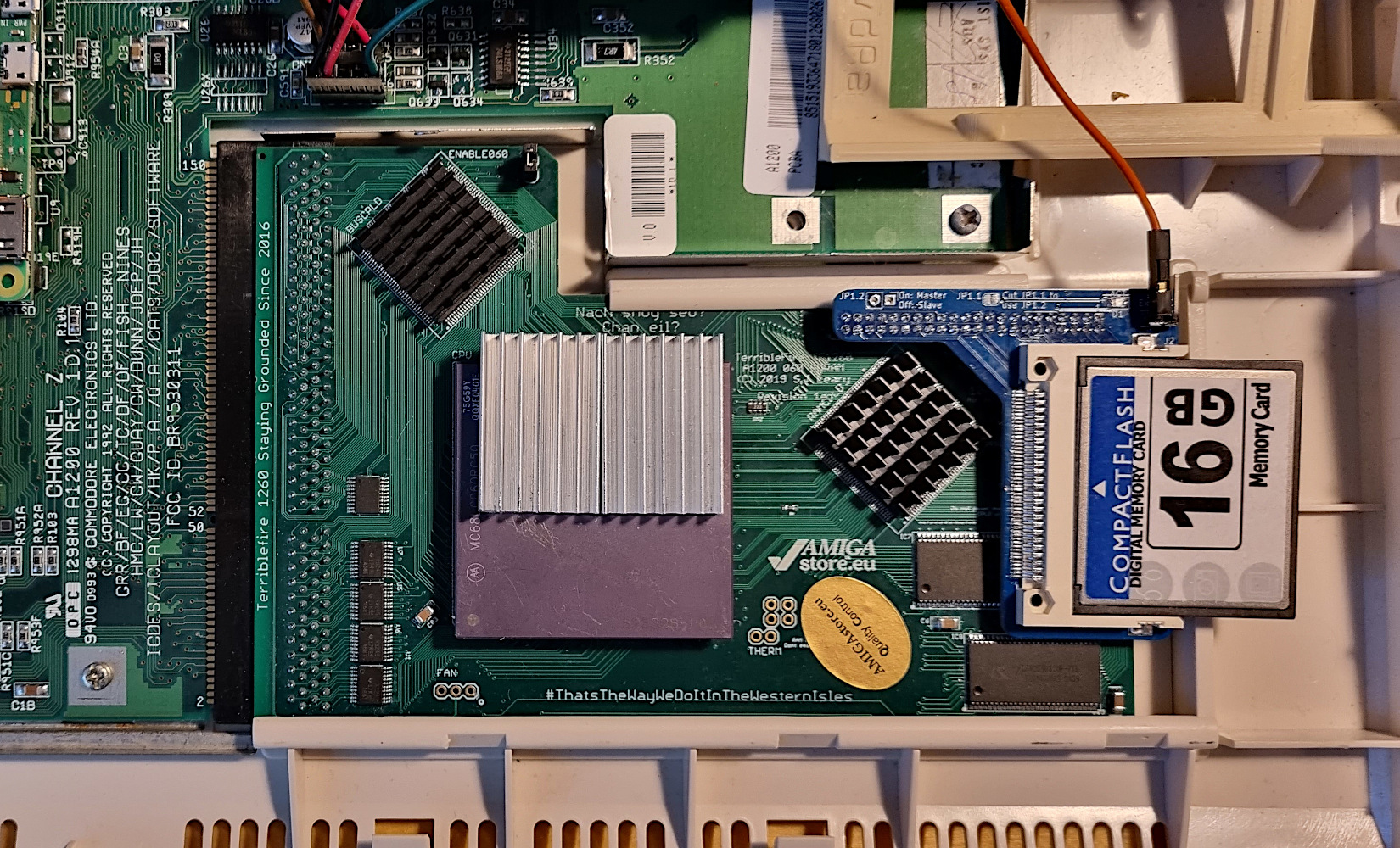
The adapter is designed to have a 44-pin female IDE-connector on the bottom side which can mate directly to the IDE controller's pin header.
If you wish to connect the adapter to an IDE cable, use a 44-pin male pin header on the top side of the adapter instead.
The external LED connector has two pins. Pin 1 which is the right pin (square pad) is active low and the pin 2 which is the left PIN is the inverted version of pin 1.
You can connect just on of the pins to an LED if the LED is connected to either ground or +5V (or similar).
Depending on if the LED you are connecting has a current limiting resistor, you may or may not need to add a resistor on the adapter. That is either R3 or R4. On the pins where you don't need resistors, simply add a solder blob to close the corresponding jumper (JP3 or JP4)
You can also connect an LED across both pins. If you do, add one resistor to either of the pins and add a solder blob to the jumper for the other pin.
JP4/R4 is for pin 1
JP3/R3 is for pin 2
Some LED configurations examples:
The optional U4 is optional. If you wish to leave U4 out and drive the LEDs directly from the CF card, you need to close jumper JP2 to let the signal pass by the unpopulated U4 footprint.
The jumpers JP1.1 and JP1.2 are used for setting master/slave configuration. JP1.1 is bridged by default and configures the drive as master.
If you wish to use the drive in a slave configuration you should cut JP1.1 and optionally install a master/slave jumper at JP1.2 or add a solder blob at JP1.1 when you want to set the drive as master again.
If JP1.1 is uncut or closed with a solder blob, JP1.2 has no effect at at.
| Qty | Value | Footprint | References |
|---|---|---|---|
| 5 | 100n | Capacitor_SMD:C_0603_1608Metric_Pad1.08x0.95mm_HandSolder | C1, C2, C3, C4, C5 |
| 3 | SN74HCT245PWR | Package_SO:TSSOP-20_4.4x6.5mm_P0.65mm | U1, U2, U3 |
| 2 | 560R | Resistor_SMD:R_0603_1608Metric_Pad0.98x0.95mm_HandSolder | R3, R4 |
| 2 | LOGO | LOGO | OSHW, retroninja |
| 1 | 101D-TAAB-R01 | Per:101DTAABR01 | U5 |
| 1 | 10k | Resistor_SMD:R_0603_1608Metric_Pad0.98x0.95mm_HandSolder | R2 |
| 1 | 1k | Resistor_SMD:R_0603_1608Metric_Pad0.98x0.95mm_HandSolder | R1 |
| 1 | 4.7k | Resistor_SMD:R_0603_1608Metric_Pad0.98x0.95mm_HandSolder | R5 |
| 1 | 74AHCT1G17 | Package_TO_SOT_SMD:SOT-23-5_HandSoldering | U4 |
| 1 | Ext. LED | Connector_PinHeader_2.54mm:PinHeader_1x02_P2.54mm_Vertical | J2 |
| 1 | IDE Connector | Connector_PinHeader_2.00mm:PinHeader_2x22_P2.00mm_Vertical | J1 |
| 1 | LED | LED_SMD:LED_0805_2012Metric_Pad1.15x1.40mm_HandSolder | D1 |
| 1 | MMBT3906 | Package_TO_SOT_SMD:SOT-23 | Q1 |
| 1 | Master | Jumper:SolderJumper-2_P1.3mm_Bridged_RoundedPad1.0x1.5mm | JP1.1 |
| 1 | Master/Slave | Connector_PinHeader_2.54mm:PinHeader_1x02_P2.54mm_Vertical | JP1.2 |
| 1 | R3 Bypass | Jumper:SolderJumper-2_P1.3mm_Open_RoundedPad1.0x1.5mm | JP3 |
| 1 | R4 Bypass | Jumper:SolderJumper-2_P1.3mm_Open_RoundedPad1.0x1.5mm | JP4 |
| 1 | U4 Bypass | Jumper:SolderJumper-2_P1.3mm_Open_RoundedPad1.0x1.5mm | JP2 |

Dschadu/Geistwerk-BigCore
An ESP32-based open hardware control board designed for Bottango-powered animatronic and motion projects.


Resident-X/brew-state
brew-state: bare-metal C state estimation and forward-horizon profiling for the Sunbeam EM7000. Built with Staircase.


robhaswell/RGB-controller
A 10-channel RGB controller based on the ESP32 microcontroller

ansemjo/chronovfd
hardware project for a clock around a russian ivl2-5/7 vfd and an esp32-wroom module

Papipapito/MSXgoauld_fusion
Placas MSX Goa'uld SD (Tang Nano 20K) con conector ZIF FFC de 40 vías: en el zócalo del Z80 o por cable con goauldext. Versiones 1.7b, 1.8N y 1.8S. Derivado de jabadiagm (GPL-3.0).
It measures 59.2 × 59.2 mm and has 2 copper layers, 1.6 mm thick.
26 parts, built around the SN74HCT245PWR(LX), 74AHCT1G17GWH, 101D-TAAB-R01 and MMBT3906. The full list of its parts is on this page, with links to each part's symbol and footprint where PCBKit's library has them.
From the RetroNynjah/Buffered-IDE2CF-adapter repository on GitHub, at the commit this page was made from: the board is rev1/schematics/Buffered IDE2CF adapter Rev 1.kicad_pcb and its schematic rev1/schematics/Buffered IDE2CF adapter Rev 1.kicad_sch. PCBKit opens the board in the browser, with nothing to install.
Its repository publishes it under the GPL-3.0 licence: you may reuse it on that licence's terms (keep the author's notice, and for a copyleft licence share your changes alike).