2 layers16 × 15 mm
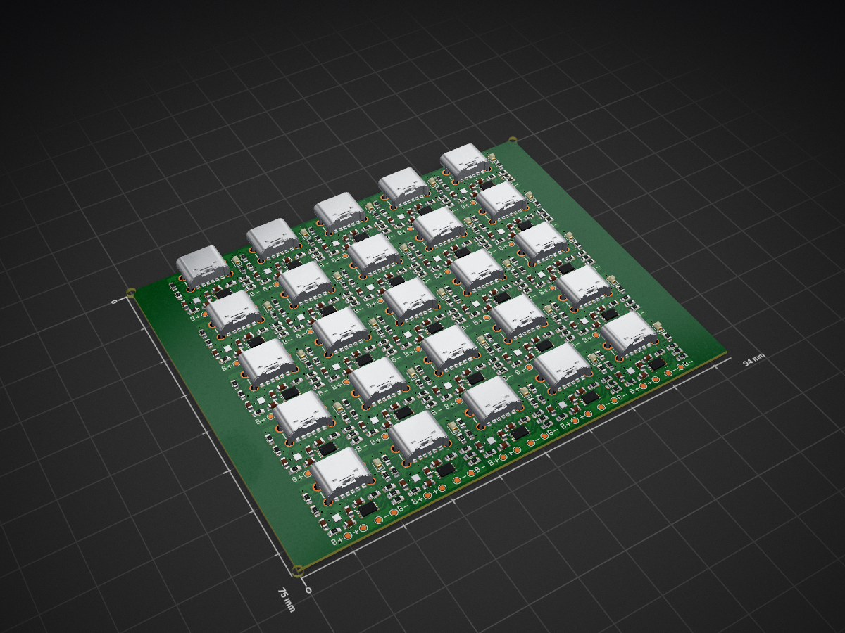
 RasmusKoit/voltage_adjuster
Voltage adjuster panel is an open-source printed circuit board by RasmusKoit, from the RasmusKoit/voltage_adjuster repository on GitHub. It is a 2-layer board of 94 × 75 mm with 609 parts on 375 nets, routed with 4,150 tracks and 600 vias.
It is built around the LDK130PU-R, LMK107B7105KA-T and LMK107BJ475KA-T, with the CRG0603F5K1, CRG0603F1K5 and CRG0603F56K among its other parts. Its parts include 200 resistors, 100 capacitors, 50 ICs, 25 diodes and 25 connectors.


| Qty | Value | Footprint | References |
|---|---|---|---|
| 100 | TestPoint_Small | TestPoint:TestPoint_Pad_D1.0mm | TP1, TP1, TP1, TP1, TP1, TP1, TP1, TP1, TP1, TP1, TP1, TP1, TP1, TP1, TP1, TP1 +84 |
| 75 | Jumper_2_Small_Open | Jumper:SolderJumper-2_P1.3mm_Open_RoundedPad1.0x1.5mm | JP1, JP1, JP1, JP1, JP1, JP1, JP1, JP1, JP1, JP1, JP1, JP1, JP1, JP1, JP1, JP1 +59 |
| 50 | 1uF | Capacitor_SMD:C_0603_1608Metric | C3, C3, C3, C3, C3, C3, C3, C3, C3, C3, C3, C3, C3, C3, C3, C3 +34 |
| 50 | 4.7uF | Capacitor_SMD:C_0603_1608Metric | C1, C1, C1, C1, C1, C1, C1, C1, C1, C1, C1, C1, C1, C1, C1, C1 +34 |
| 50 | 5.1k | Resistor_SMD:R_0603_1608Metric | R3, R3, R3, R3, R3, R3, R3, R3, R3, R3, R3, R3, R3, R3, R3, R3 +34 |
| 25 | 1.5k | Resistor_SMD:R_0603_1608Metric | R2, R2, R2, R2, R2, R2, R2, R2, R2, R2, R2, R2, R2, R2, R2, R2 +9 |
| 25 | 100k | Resistor_SMD:R_0603_1608Metric | R6, R6, R6, R6, R6, R6, R6, R6, R6, R6, R6, R6, R6, R6, R6, R6 +9 |
| 25 | 124k | Resistor_SMD:R_0603_1608Metric | R7, R7, R7, R7, R7, R7, R7, R7, R7, R7, R7, R7, R7, R7, R7, R7 +9 |
| 25 | 316k | Resistor_SMD:R_0603_1608Metric | R8, R8, R8, R8, R8, R8, R8, R8, R8, R8, R8, R8, R8, R8, R8, R8 +9 |
| 25 | 56k | Resistor_SMD:R_0603_1608Metric | R1, R1, R1, R1, R1, R1, R1, R1, R1, R1, R1, R1, R1, R1, R1, R1 +9 |
| 25 | 88.7k | Resistor_SMD:R_0603_1608Metric | R5, R5, R5, R5, R5, R5, R5, R5, R5, R5, R5, R5, R5, R5, R5, R5 +9 |
| 25 | LDK130PU-R | footprints_symbols:LDK130PUR | IC1, IC1, IC1, IC1, IC1, IC1, IC1, IC1, IC1, IC1, IC1, IC1, IC1, IC1, IC1, IC1 +9 |
| 25 | LED | LED_SMD:LED_0603_1608Metric | D1, D1, D1, D1, D1, D1, D1, D1, D1, D1, D1, D1, D1, D1, D1, D1 +9 |
| 25 | MCP73832T-2ACI_MC | footprints_symbols:SON50P300X200X100-9N-D | IC2, IC2, IC2, IC2, IC2, IC2, IC2, IC2, IC2, IC2, IC2, IC2, IC2, IC2, IC2, IC2 +9 |
| 25 | TestPoint_Small | Art:Salt-8x8 | TP3, TP3, TP3, TP3, TP3, TP3, TP3, TP3, TP3, TP3, TP3, TP3, TP3, TP3, TP3, TP3 +9 |
| 25 | UJC-H-G-SMT-1-P6-TR | footprints_symbols:UJCHGSMT1P6TR | J1, J1, J1, J1, J1, J1, J1, J1, J1, J1, J1, J1, J1, J1, J1, J1 +9 |
| 6 | Fiducial | Fiducial | KiKit_FID_B_1, KiKit_FID_B_2, KiKit_FID_B_3, KiKit_FID_T_1, KiKit_FID_T_2, KiKit_FID_T_3 |
| 3 | NPTH | NPTH | KiKit_TO_1, KiKit_TO_2, KiKit_TO_3 |


BetzDrive/interface-board
Power and signal conditioning board for the Betz Drive system


abendezu10/PulseWatch
Developed a fully functional smartwatch using an STM32 microcontroller, featuring real-time heart rate monitoring.


Ozonised/FeroFlyF405
FeroFlyF405 an open source STM32F405 based flight controller running INAV
It measures 94 × 75 mm and has 2 copper layers, 0.8 mm thick.
609 parts, built around the LDK130PU-R, LMK107B7105KA-T, LMK107BJ475KA-T and CRG0603F5K1. The full list of its parts is on this page, with links to each part's symbol and footprint where PCBKit's library has them.
From the RasmusKoit/voltage_adjuster repository on GitHub, at the commit this page was made from: the board is voltage_adjuster_panel.kicad_pcb and its schematic voltage_adjuster.kicad_sch. PCBKit opens the board in the browser, with nothing to install.
Its repository states no licence, so its author keeps all rights: ask RasmusKoit before reusing the design.