
2 layers299 × 82.5 mm
PixelWave
hackclub/OnBoard
💡 Join 1,000 teenagers and make your first PCB with a $100 grant!
663 parts915

Open-source 6-DOF robot arm controller using STM32F411, Dynamixel servos, custom KiCad PCB, PWM gripper control, data logging, and planned ESP32-C3 wireless communication.
6dof is an open-source printed circuit board by Ramahabir, from the Ramahabir/6-DOF-Robotics-Arm-Dynamixel repository on GitHub, published under the MIT licence. It is a 2-layer board of 134.5 × 70 mm with 17 parts on 69 nets, routed with 158 tracks and 16 vias.
It is built around the STM32F411CEU6, 74LS241P-E and XL4016E1. Its parts include 11 connectors and 2 ICs. It belongs with the robots and motor control boards and the STM32 boards of this library.


Firmware for a 6-degree-of-freedom robot arm based on an STM32F411CEU6 (Black Pill). The controller is designed to operate four Dynamixel joints over a half-duplex serial bus and two conventional PWM servos for the end effector.
The project uses STM32Cube HAL with PlatformIO and is uploaded/debugged through ST-Link.
The repository includes the editable KiCad source for the custom controller PCB. The board combines the STM32F411 Black Pill, ESP32-C3 Super Mini, 74LS241 Dynamixel interface, power input, actuator connectors, and development headers on one carrier board.
Open pcb/6dof.kicad_pro in KiCad 9.0 or newer to view or modify the complete project.
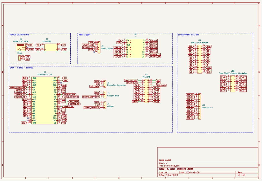
Editable source: pcb/6dof.kicad_sch
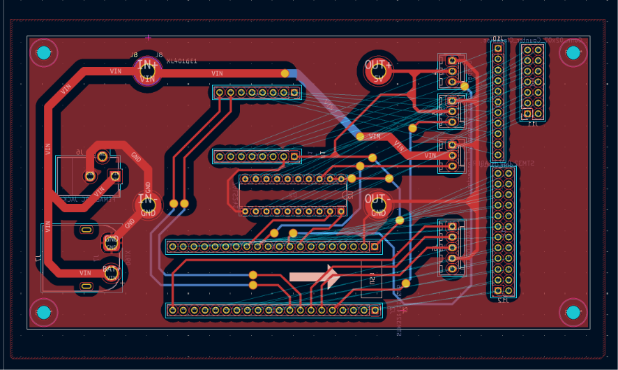
Editable source: pcb/6dof.kicad_pcb
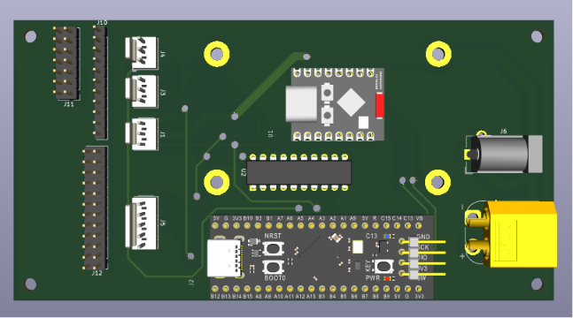
The KiCad files are active design sources. Review the schematic, complete the design-rule checks, and verify all footprints and routing before ordering a PCB. Gerber files, drill files, and a bill of materials are not included yet.
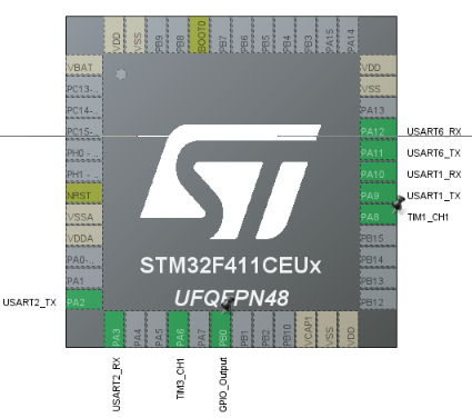
| Function | STM32 peripheral | Pin | Direction | Notes |
|---|---|---|---|---|
| Dynamixel TX | USART2_TX | PA2 | Output | 1 Mbps, 8-N-1 |
| Dynamixel RX | USART2_RX | PA3 | Input | Receives Dynamixel status packets |
| 74LS241 direction | GPIO | PB0 | Output | High = transmit, low = receive/bus released |
| Data logger TX | USART1_TX | PA9 | Output | Connect to USB-to-TTL RX |
| Data logger RX | USART1_RX | PA10 | Input | Connect to USB-to-TTL TX |
| ESP32-C3 TX | USART6_TX | PA11 | Output | Planned wireless link; connect to ESP32 RX |
| ESP32-C3 RX | USART6_RX | PA12 | Input | Planned wireless link; connect to ESP32 TX |
| Gripper rotation servo | TIM1_CH1 | PA8 | PWM output | Rotates the gripper |
| Gripper servo | TIM3_CH1 | PA6 | PWM output | Opens and closes the gripper |
| Built-in status LED | GPIO | PC13 | Output | Active-low on the Black Pill |
The USART1 pin assignment above follows the target hardware pinout. The generated firmware currently maps USART1 to PB6/PB7; update the alternate-function configuration to PA9/PA10 before wiring the logger to those target pins.
Dynamixel Protocol 1.0 uses a single bidirectional data wire. USART2 provides separate TX and RX signals, so the 74LS241 is used to control when the STM32 drives the bus.
STM32 PA2 (USART2_TX) ──> 74LS241 input
STM32 PB0 (DIR)       ──> 74LS241 output-enable/direction control
74LS241 bus output    ──> Dynamixel DATA
STM32 PA3 (USART2_RX) <── Dynamixel DATA / receive path

STM32 GND ─────────────── Dynamixel interface GND
The firmware sets PB0 high while transmitting and returns it low before waiting for a servo response. USART2 is configured for 1,000,000 baud, 8 data bits, no parity, and 1 stop bit.
Do not power the actuators from the STM32 board. Use correctly rated external supplies and connect the grounds of the STM32, servo supplies, Dynamixel bus, USB-to-TTL adapter, and ESP32 interface.
The earlier arm configuration stored in this repository uses the following IDs and zero offsets:
| Joint | Dynamixel ID | Home position | Approx. offset | Positive direction |
|---|---|---|---|---|
| Base | 1 | 493 | 144.57° | Counterclockwise |
| Shoulder | 9 | 308 | 90.32° | Counterclockwise |
| Elbow | 13 | 481 | 141.35° | Counterclockwise |
The current test program in src/main.c controls Dynamixel ID 4, moving it between raw positions 350 and 650. Confirm every actuator ID and mechanical zero before enabling torque on the assembled arm.
For AX-series position control, raw values 0..1023 represent approximately 0..300°:
angle = raw_position × 300 / 1023Currently implemented:
Still to be integrated into the active application:
At present, main() initializes only GPIO and USART2. The other peripheral configuration files exist but are not yet called by the active program.
Build the firmware:
pio runUpload through ST-Link:
pio run --target uploadOpen the serial monitor for logger output once USART1 logging is enabled:
pio device monitor --baud 115200The PlatformIO environment is genericSTM32F411CE, using the STM32Cube framework and ST-Link for upload and debugging.
.
├── include/
│   ├── dynamixel.h       # Dynamixel driver API and control-table addresses
│   ├── gpio.h
│   ├── main.h
│   ├── tim.h
│   └── usart.h
├── docs/
│   ├── 3dpcb.png         # Render of the assembled controller PCB
│   ├── pcb_footprint.png # PCB routing and footprint preview
│   ├── schematic.png     # Controller schematic preview
│   └── stm32pinout.png   # STM32 peripheral pin assignment
├── pcb/
│   ├── 6dof.kicad_pcb    # Editable PCB layout
│   ├── 6dof.kicad_pro    # KiCad project settings
│   └── 6dof.kicad_sch    # Editable schematic
├── src/
│   ├── dynamixel.c       # Protocol 1.0 packet transport and commands
│   ├── gpio.c            # LED and 74LS241 direction GPIO setup
│   ├── main.c            # Active test application
│   ├── tim.c             # PA8 and PA6 PWM timer configuration
│   └── usart.c           # USART1 and USART2 configuration
├── main_lama/            # Earlier application code kept for reference
└── platformio.ini # PlatformIO target and build configurationThis project is open-source software available under the MIT License.
| Qty | Value | Footprint | References |
|---|---|---|---|
| 1 | 74LS241 | Package_DIP:DIP-20_W7.62mm | U2 |
| 1 | Conn_01x11 | Connector_PinHeader_2.54mm:PinHeader_1x11_P2.54mm_Vertical | J10 |
| 1 | Conn_02x07_Counter_Clockwise | Connector_PinHeader_2.54mm:PinHeader_2x07_P2.54mm_Vertical | J11 |
| 1 | Dynamixel Connector | Connector_Molex:Molex_KK-254_AE-6410-03A_1x03_P2.54mm_Vertical | J1 |
| 1 | FEMALE DC JACK | Connector_BarrelJack:BarrelJack_CUI_PJ-102AH_Horizontal | J6 |
| 1 | Gripper | Connector_Molex:Molex_KK-254_AE-6410-03A_1x03_P2.54mm_Vertical | J4 |
| 1 | Gripper Wrist | Connector_Molex:Molex_KK-254_AE-6410-03A_1x03_P2.54mm_Vertical | J3 |
| 1 | STM32 DEV HEADER | Connector_PinHeader_2.54mm:PinHeader_2x12_P2.54mm_Vertical | J12 |
| 1 | STM32F411CEU6 | buatan aing nih:STM32F411CEU6 | J2 |
| 1 | UART_LOGGER | Connector_Molex:Molex_KK-254_AE-6410-05A_1x05_P2.54mm_Vertical | J5 |
| 1 | XL4016E1 | buatan aing nih:XL4016E1 | J8 |
| 1 | XT60 | Connector_AMASS:AMASS_XT60PW-M_1x02_P7.20mm_Horizontal | J7 |
| 1 | ~ | buatan aing nih:ESP32 C3 SUPERMINI | U1 |
The 13 most common of 17 parts.
hackclub/OnBoard
💡 Join 1,000 teenagers and make your first PCB with a $100 grant!

rayvburn/diff_drive_mapping_robot
ROS driver for the Raspberry Pi based differential drive robot


3stan-H/Bench-Power-Supply
A mains-powered, adjustable bench power supply designed in KiCad, converting 120V AC wall input into a regulated 1–20V DC output.


iamdarshg/edf-esc
Open hardware and firmware for a compact 98 mm × 58 mm, four-layer board with two independent 6S sensorless BLDC/EDF controller channels.

It measures 134.5 × 70 mm and has 2 copper layers, 1.6 mm thick.
17 parts, built around the STM32F411CEU6, 74LS241P-E and XL4016E1. The full list of its parts is on this page, with links to each part's symbol and footprint where PCBKit's library has them.
From the Ramahabir/6-DOF-Robotics-Arm-Dynamixel repository on GitHub, at the commit this page was made from: the board is pcb/6dof.kicad_pcb and its schematic pcb/6dof.kicad_sch. PCBKit opens the board in the browser, with nothing to install.
Its repository publishes it under the MIT licence: you may reuse it on that licence's terms (keep the author's notice, and for a copyleft licence share your changes alike).