4 layers68 × 60 mm
RoboCore
Plastal-Bot-Builders/RoboCoreDocumentation
RoboCore is a classroom robot kit and coding platform, designed and built in Zambia by Plastal-Bot Builders (Lusaka).
104 partsMIT

 Plastal-Bot-Builders/RoboCoreDocumentation
RoboCore is a classroom robot kit and coding platform, designed and built in Zambia by Plastal-Bot Builders (Lusaka).
RoboCore V2 is an open-source printed circuit board by Plastal-Bot-Builders, from the Plastal-Bot-Builders/RoboCoreDocumentation repository on GitHub, published under the MIT licence. It is a 4-layer board of 68 × 60 mm with 146 parts on 109 nets, routed with 1,810 tracks and 243 vias.
It is built around the ESP32-S3-WROOM-1-N8R2, TPS61089RNRR and LSM6DSOX, with the MCP73871-2CCI/ML, TPS3700DSE and USBLC6-2SC6 among its other parts. Its parts include 54 resistors, 35 capacitors, 13 connectors, 9 diodes and 8 ICs. It belongs with the ESP32 boards of this library.


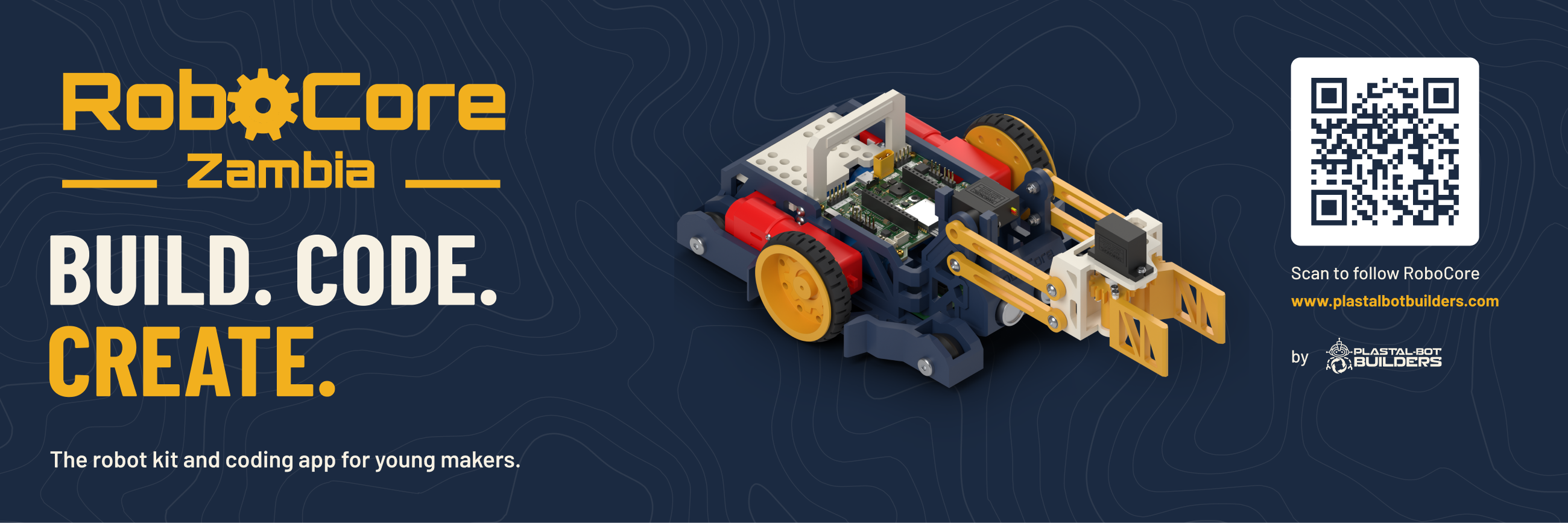
RoboCore is a classroom robot kit and coding platform, designed and built in Zambia by Plastal-Bot Builders (Lusaka). It has four parts:
This repository holds the design sources for all of it: the PCBs, the mechanical design, the software design and the brand. Pitch decks, grant applications and community posts live elsewhere.
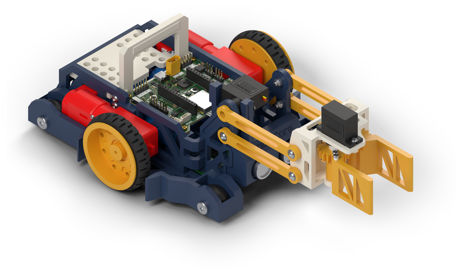 | 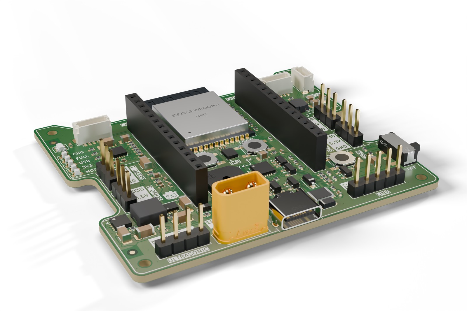 |
| The robot (V2, Fusion 360) | The controller board (V2, KiCad 9) |
An XRP-style robot controller on a 68 × 60 mm, 4-layer board. Everything a classroom robot needs is on one board, and it charges and programs over one USB-C cable.
| Brain | ESP32-S3-WROOM-1-N8R2: dual core, Wi-Fi and Bluetooth LE, 8 MB flash, 2 MB PSRAM. Programs over native USB, so no separate programmer is needed |
| Motors | 2 DC motors with encoders (DRV8411A dual H-bridge, limited to 1.0 A per motor). JST SH 6-pin, matching the SparkFun XRP motors |
| Servos | 4 servo ports on a 5.5 V supply (TPS61089 boost, about 2.5–3 A continuous) |
| Sensors | Ultrasonic port (4-pin), 3-channel line-sensor port (5-pin, analog), Qwiic I2C, and an LSM6DSOX 6-axis motion sensor on board |
| Power | One Li-ion cell, or several in parallel (3.0–4.2 V), on an XT30 plug. Protected against a reversed or over-voltage pack. USB-C charging at 1 A (MCP73871) and a steady 3.3 V from a buck-boost converter |
| On board | RGB LED, buzzer, RESET, BOOT and USER buttons, charge and power LEDs, two 14-pin expansion headers |
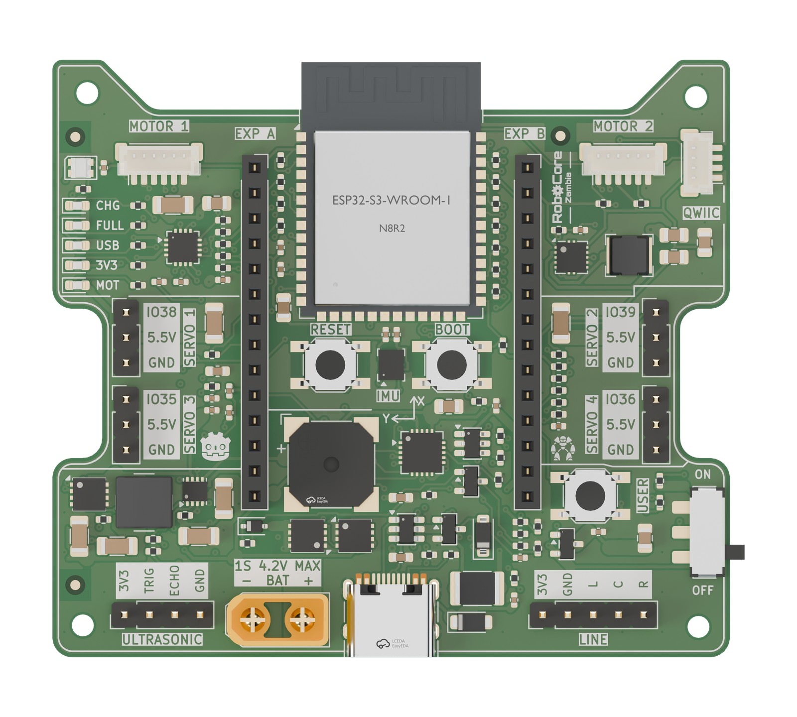 | 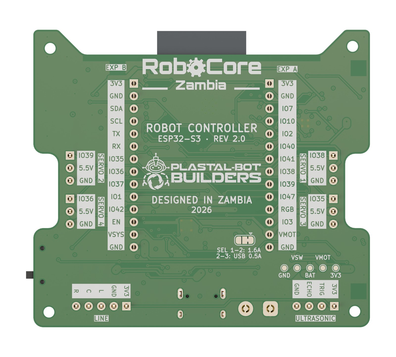 |
| Top: every port labelled on the silkscreen | Underside: pin names and the "Designed in Zambia" artwork |
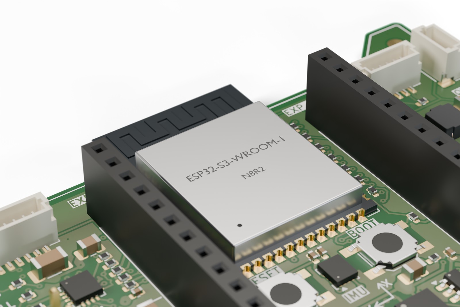 | 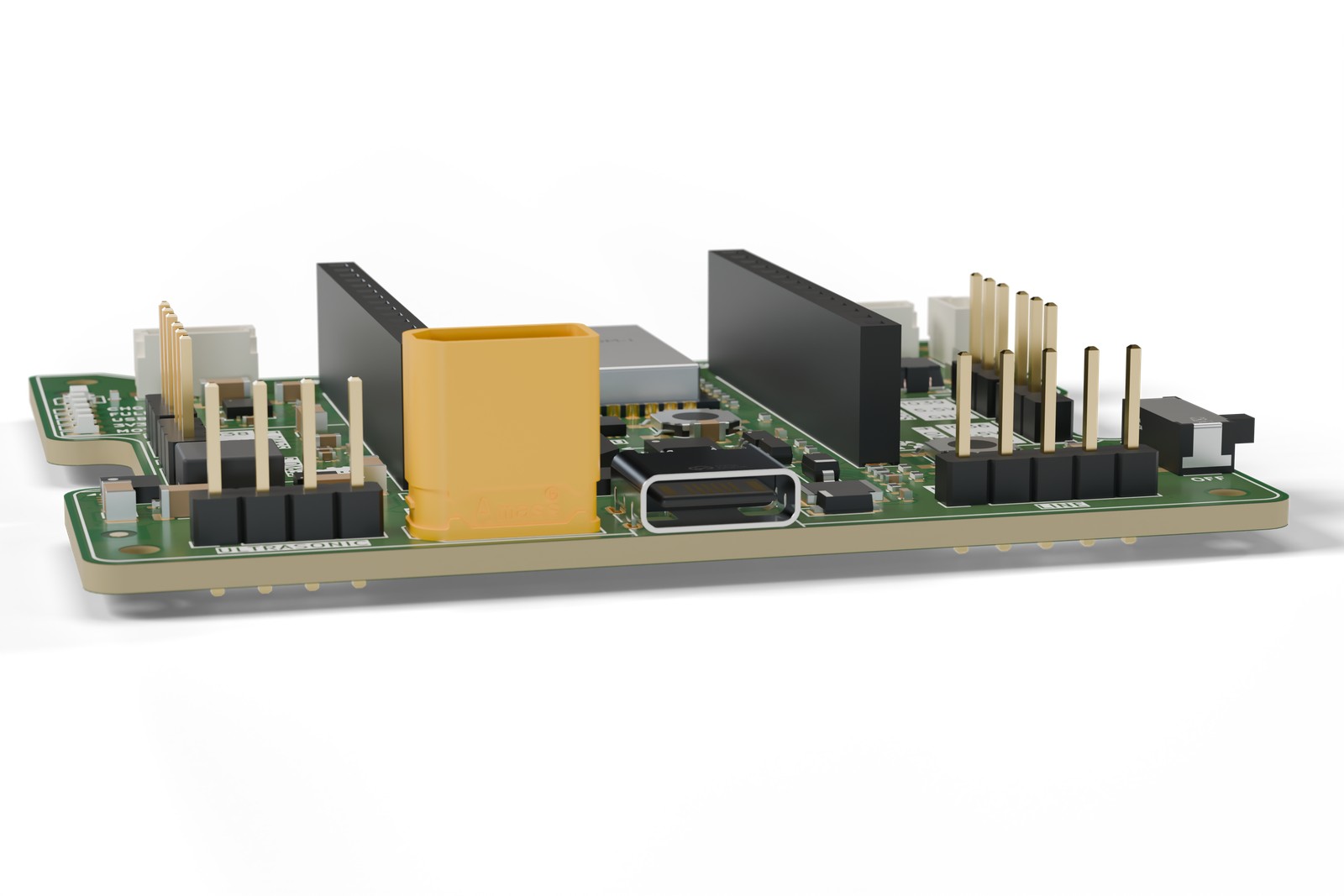 |
| The ESP32-S3 module, buttons and IMU | The connector edge: ultrasonic, battery, USB-C, line sensor, power switch |
hardware/controller_v2/. Open RoboCore_V2.kicad_pro in KiCad 9.hardware/controller_v2/renders/, full size and 1600 px, with transparent and white backgrounds. Each shot has a map of where every part sits in the image, for pinouts and highlights in the IDE or on the website. See its README.hardware/sensors/. For now the robot uses bought-in modules.The current robot (V3, the V-wheel version): an open printed frame with Warren-truss sides, two encoder motors with 56 mm wheels, four V-wheels in wheel wells, a parallel four-bar lift on one MG90S servo (the gripper stays level from the floor to +40 degrees) and a geared gripper on a second servo. The RoboCore V2 controller sits between the side frames, three 18650 cells lie in a printed cradle, the sonar sits in a housing at the front, and a cream rear deck carries an 8 mm Technic/M4 hole grid. 154 x 286 x 111 mm with the lift level, about 620 g; every part prints flat without supports. The V3 model lives in Fusion 360 (document "RoboCore V3 Robot"); the files below are the earlier V2 robot, kept for reference.
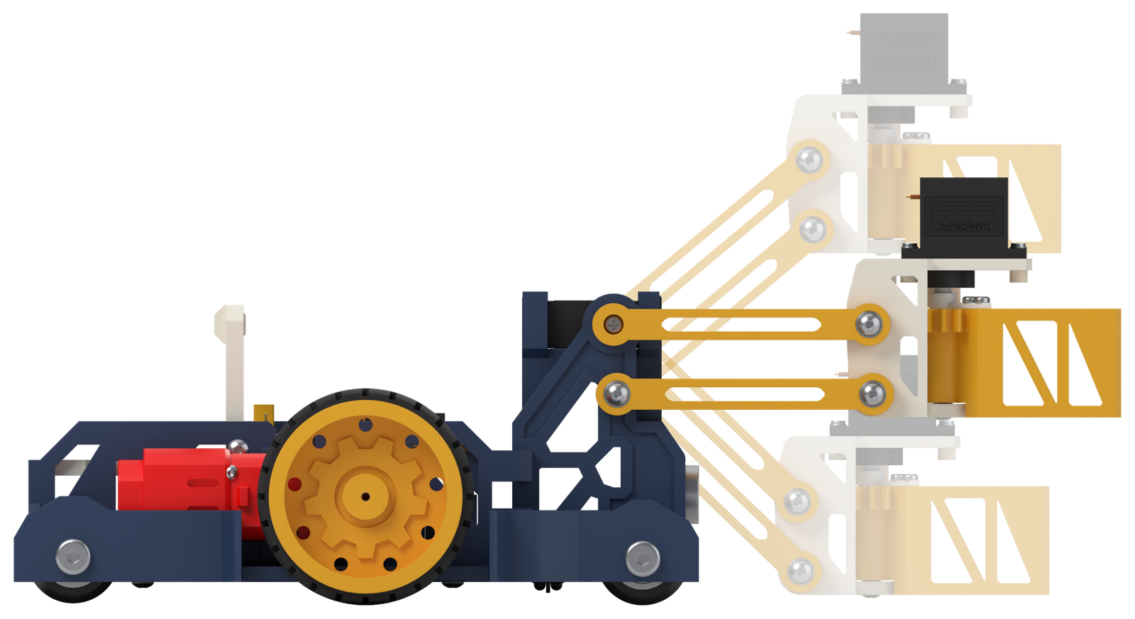
mechanical/robot_v2/RoboCore_V2_Robot.f3d (Fusion 360) and .step (any CAD program).mechanical/robot_v2/fusion/). Its README explains the parameters, the fasteners and the checks: clashes, overhangs, antenna clearance and caster load.mechanical/robot_v2/print/, already in print orientation. Every part prints without supports on a 180 mm bed.mechanical/robot_v2/cardboard/.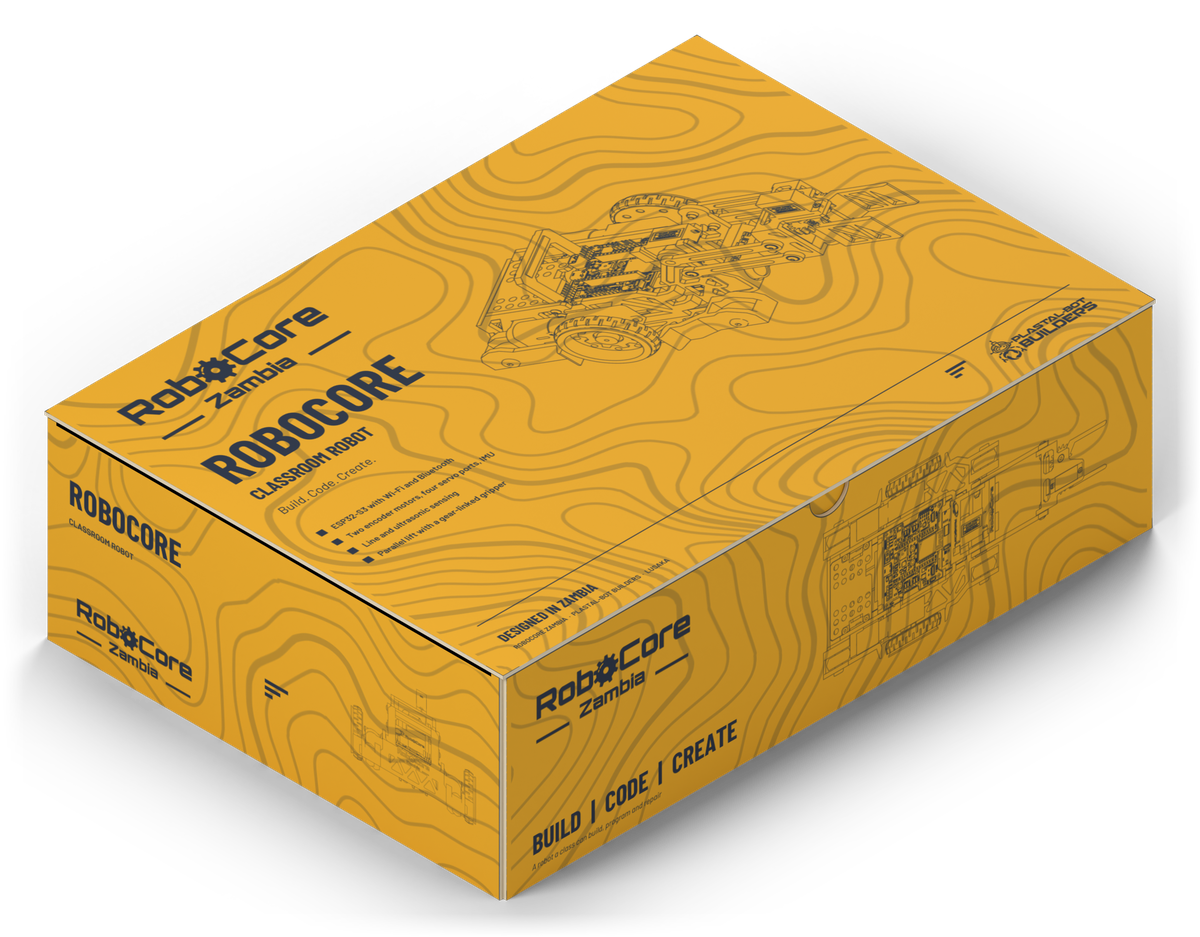 | 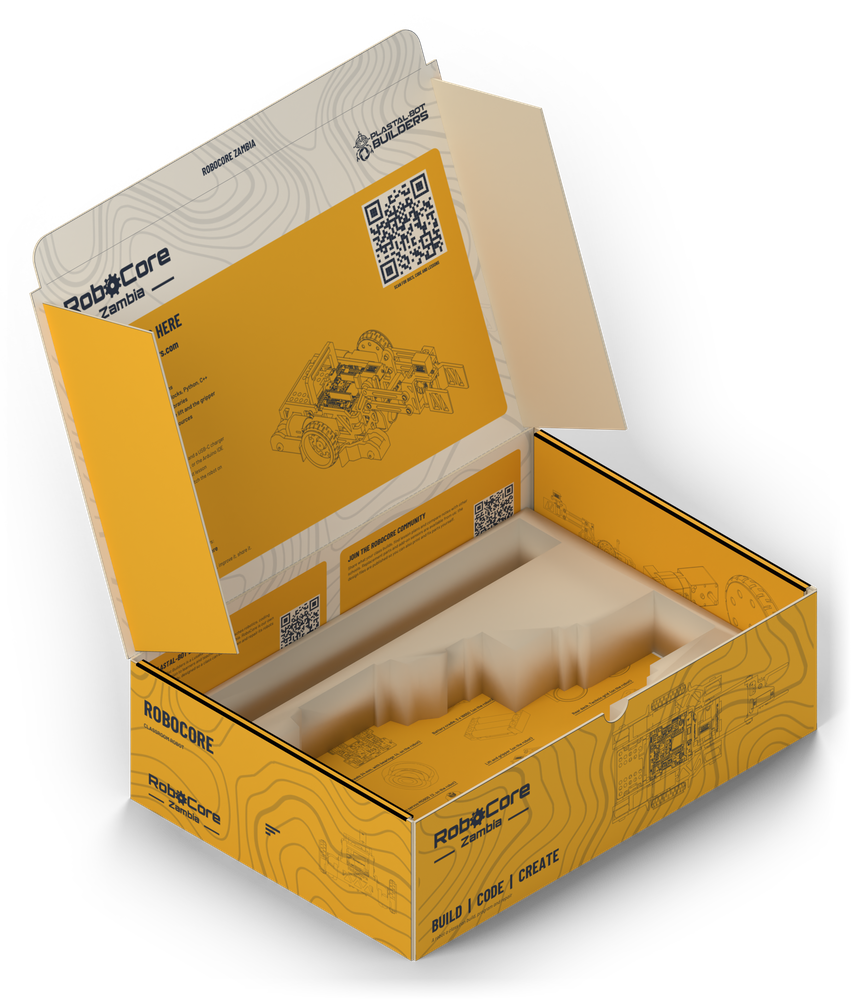 |
A printed mailer box, XRP-style, with the quick-start guide printed inside the lid and an insert with a pocket traced from the robot (lift lowered, jaws on the floor) plus a strip for the cable, screws and card. Outer 303 x 213 x 91 mm. The print-ready 1:1 PDFs are in mechanical/robot_v2/packaging/out_v3/ (generator make_box_v3.py; the V2 box is in out/).
software/ide_design/): the screens of the RoboCore IDE, built in Figma by a plugin. It covers block coding (Google Blockly) and C++ (Monaco), a hardware-first block catalogue, and a behaviour spec. The app itself is developed in its own repository, robocore-ide.software/architecture/): UML and C4 diagrams of the whole platform, also generated into Figma.software/firmware/motion/): an arm-aware braking limiter in C, with tests.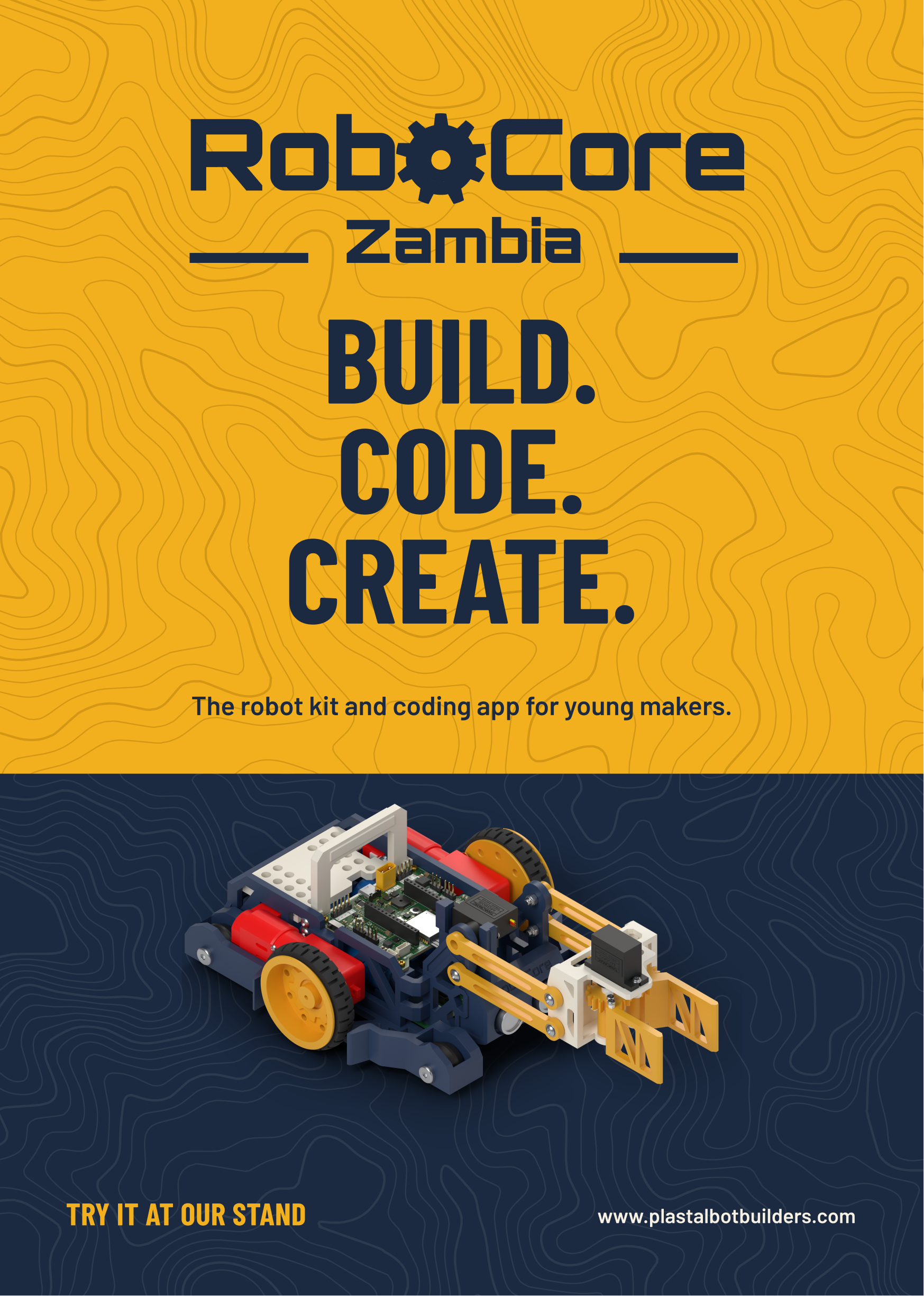 | 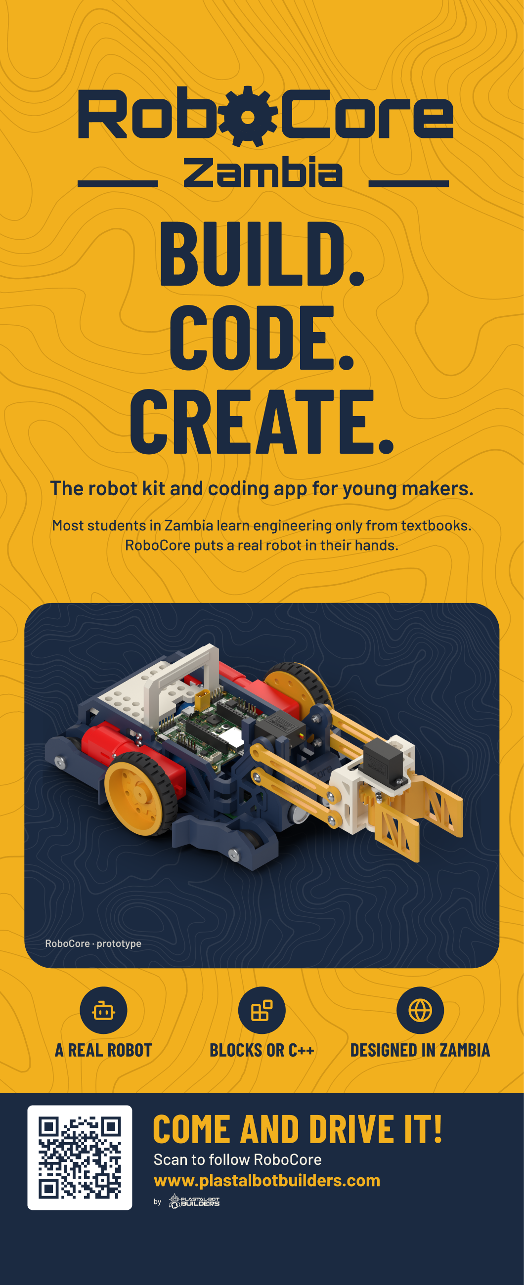 | 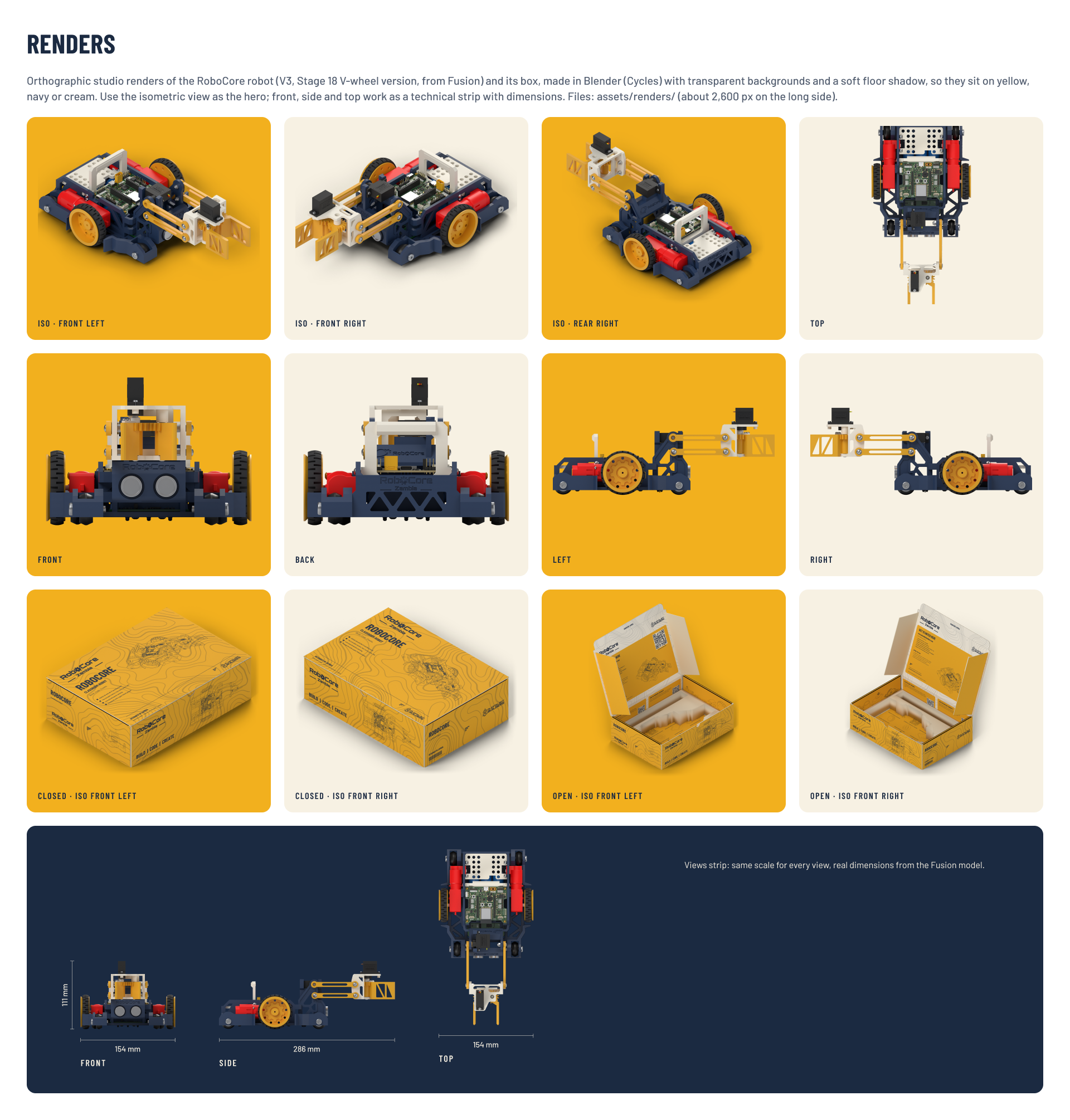 |
Event branding is in design/event_branding/: roll-up, pop-up, banner, A5 flyer, A4 tri-fold and the brand kit, built in Figma by a plugin. The topographic backgrounds are drawn from Copperbelt elevation data.
hardware/          PCB design (KiCad 9)
  controller_v2/     RoboCore V2 controller: project files, libraries (lib/), PCBWay and JLCPCB order
                     packages (fab/), generator, check, costing and Blender render scripts (tools/),
                     silkscreen artwork sources (technicalreference/), studio renders (renders/)
  sensors/           Line sensor (3-channel) and ultrasonic carrier boards for V2
  controller_v1/     RoboCore V1 (ESP32-C3) controller with its fab package and review scripts
  libraries/         Shared symbol and footprint libraries used by V1
  datasheets/        Component datasheets
mechanical/        Mechanical design
  robot_v2/          The Fusion 360 robot: model, Python generator (fusion/), print files (print/),
                     component STEP exports (export/), mailer box (packaging/), cardboard version
                     (cardboard/), vendor models (vendor/), renders
  board_step/        STEP models of the boards, for mechanical integration
  reference/         Motor and XRP reference pictures and models
  chassis_v1_spec/   Specification and script of the V1 chassis
software/          Software
  ide_design/        RoboCore IDE screens (Figma plugin), app icon, block catalogue, behaviour spec
  architecture/      UML + C4 system architecture (Figma plugin)
  firmware/motion/   Arm-aware braking limiter (C, with tests)
design/            Brand
  event_branding/    Roll-up, banner, flyer, tri-fold and brand kit (Figma plugin), topographic maps
docs/              Specification, costing and sourcing, component lists and supplier quote requests,
                   wrong-plug check and errata, schematic PDFs, part photos, A4 technical-reference
                   posters, progress renders, hand-off notes, PCBWay sponsorship request
tools/ sync_from_sources.sh: copies the working sources into this repohardware/controller_v2/RoboCore_V2.kicad_pro in KiCad 9. Project libraries resolve through ${KIPRJMOD}/lib; the V1 project's symbol table points at ../libraries.mechanical/robot_v2/RoboCore_V2_Robot.f3d opens in Fusion 360; the STEP beside it opens anywhere.mechanical/robot_v2/packaging/README.md. The print files are 1:1 PDFs.hardware/controller_v2/tools/blender/render_board.sh re-renders them in Blender 5.1, from the KiCad model.software/ide_design/, software/architecture/ and design/event_branding/ explain how to load and run each plugin.docs/.The design work happens in working folders outside this repo. Copy it in, then commit:
tools/sync_from_sources.sh           # list what changed
tools/sync_from_sources.sh --apply   # copy it in
The script lists every source folder it copies. On a slow connection, push large changes in several small commits.
MIT, see LICENSE. Vendor models under mechanical/robot_v2/vendor/ keep their own licences, noted in each folder's SOURCE.txt.
| Qty | Value | Footprint | References |
|---|---|---|---|
| 13 | 330 | Resistor_SMD:R_0402_1005Metric | R401, R402, R403, R404, R405, R406, R407, R408, R409, R410, R411, R412, R413 |
| 12 | 0.1uF | Capacitor_SMD:C_0402_1005Metric | C101, C106, C107, C112, C114, C120, C122, C202, C204, C205, C206, C302 |
| 10 | 10k | Resistor_SMD:R_0402_1005Metric | R103, R106, R201, R202, R203, R303, R304, R305, R306, R307 |
| 7 | 100k | Resistor_SMD:R_0402_1005Metric | R110, R117, R118, R121, R122, R123, R206 |
| 7 | 22uF | Capacitor_SMD:C_1206_3216Metric | C111, C117, C118, C119, C303, C401, C402 |
| 5 | 1k | Resistor_SMD:R_0402_1005Metric | R105, R107, R108, R109, R119 |
| 4 | M2 | MountingHole:MountingHole_2.2mm_M2 | H101, H102, H103, H104 |
| 3 | 10uF | Capacitor_SMD:C_0805_2012Metric | C105, C108, C301 |
| 3 | 22uF | Capacitor_SMD:C_0805_2012Metric | C109, C110, C201 |
| 3 | Fiducial | Fiducial:Fiducial_1mm_Mask2mm | FID101, FID102, FID103 |
| 3 | SI7655DN | Package_SO:Vishay_PowerPAK_1212-8_Single | Q102, Q103, Q104 |
| 2 | 100 | Resistor_SMD:R_0402_1005Metric | R111, R205 |
| 2 | 16.5k | Resistor_SMD:R_0402_1005Metric | R301, R302 |
| 2 | 1nF | Capacitor_SMD:C_0402_1005Metric | C304, C305 |
| 2 | 1uF | Capacitor_SMD:C_0402_1005Metric | C121, C203 |
| 2 | 300k | Resistor_SMD:R_0402_1005Metric | R113, R115 |
| 2 | 4.7k | Resistor_SMD:R_0402_1005Metric | R207, R208 |
| 2 | 5.1k | Resistor_SMD:R_0402_1005Metric | R101, R102 |
| 2 | AO3400A | Package_TO_SOT_SMD:SOT-23 | Q105, Q201 |
| 2 | GREEN | LED_SMD:LED_0603_1608Metric | D102, D104 |
| 2 | RED | LED_SMD:LED_0603_1608Metric | D101, D105 |
| 1 | +3V3 | TestPoint:TestPoint_Pad_D1.0mm | TP101 |
| 1 | +BATT | TestPoint:TestPoint_Pad_D1.0mm | TP103 |
| 1 | 1.5A | Fuse:Fuse_1812_4532Metric | F101 |
| 1 | 10nF | Capacitor_SMD:C_0402_1005Metric | C115 |
| 1 | 10uF | Capacitor_SMD:C_0603_1608Metric | C103 |
| 1 | 1M | Resistor_SMD:R_0402_1005Metric | R125 |
| 1 | 1N4148W | Diode_SMD:D_SOD-123 | D202 |
| 1 | 1N4148WS | Diode_SMD:D_SOD-323 | D107 |
| 1 | 1uF | Capacitor_SMD:C_0603_1608Metric | C102 |
| 1 | 2.2k | Resistor_SMD:R_0402_1005Metric | R120 |
| 1 | 2.2uF | Capacitor_SMD:C_0603_1608Metric | C113 |
| 1 | 2.2uH | RoboCoreV2:L_Bourns_SRP5030CA | L102 |
| 1 | 2.2uH | Inductor_SMD:L_Bourns-SRN4018 | L101 |
| 1 | 200k | Resistor_SMD:R_0402_1005Metric | R116 |
| 1 | 22pF | Capacitor_SMD:C_0402_1005Metric | C116 |
| 1 | 267k | Resistor_SMD:R_0402_1005Metric | R104 |
| 1 | 33 | Resistor_SMD:R_0402_1005Metric | R204 |
| 1 | 330k | Resistor_SMD:R_0402_1005Metric | R124 |
| 1 | 4.7uF | Capacitor_SMD:C_0805_2012Metric | C104 |
| 1 | 84.5k | Resistor_SMD:R_0402_1005Metric | R114 |
| 1 | 9.1k | Resistor_SMD:R_0402_1005Metric | R112 |
| 1 | 95.3k | Resistor_SMD:R_0402_1005Metric | R126 |
| 1 | AO3401A | Package_TO_SOT_SMD:SOT-23 | Q101 |
| 1 | BLUE | LED_SMD:LED_0603_1608Metric | D103 |
| 1 | BOOT | Button_Switch_SMD:SW_SPST_SKQG_WithoutStem | SW202 |
| 1 | CMT-8504-100-SMT | Buzzer_Beeper:MagneticBuzzer_CUI_CMT-8504-100-SMT | BZ201 |
| 1 | DRV8411ARTER | Package_DFN_QFN:WQFN-16-1EP_3x3mm_P0.5mm_EP1.68x1.68mm_ThermalVias | U301 |
| 1 | ESP32-S3-WROOM-1-N8R2 | RF_Module:ESP32-S3-WROOM-1 | U201 |
| 1 | EXPANSION_A | Connector_PinSocket_2.54mm:PinSocket_1x14_P2.54mm_Vertical | J405 |
| 1 | EXPANSION_B | Connector_PinSocket_2.54mm:PinSocket_1x14_P2.54mm_Vertical | J406 |
| 1 | GND | TestPoint:TestPoint_Pad_D1.0mm | TP104 |
| 1 | LINE_FOLLOWER | Connector_PinHeader_2.54mm:PinHeader_1x05_P2.54mm_Vertical | J404 |
| 1 | LSM6DSOX | Package_LGA:LGA-14_3x2.5mm_P0.5mm_LayoutBorder3x4y | U202 |
| 1 | MCP73871-2CCI/ML | Package_DFN_QFN:QFN-20-1EP_4x4mm_P0.5mm_EP2.5x2.5mm_ThermalVias | U102 |
| 1 | MOTOR_1 | Connector_JST:JST_SH_BM06B-SRSS-TB_1x06-1MP_P1.00mm_Vertical | J301 |
| 1 | MOTOR_2 | Connector_JST:JST_SH_BM06B-SRSS-TB_1x06-1MP_P1.00mm_Vertical | J302 |
| 1 | ON/OFF | Button_Switch_SMD:SW_SPDT_CK_JS102011SAQN | SW101 |
| 1 | Qwiic | Connector_JST:JST_SH_BM04B-SRSS-TB_1x04-1MP_P1.00mm_Vertical | J201 |
| 1 | RESET | Button_Switch_SMD:SW_SPST_SKQG_WithoutStem | SW201 |
| 1 | SEL | Jumper:SolderJumper-3_P1.3mm_Bridged12_RoundedPad1.0x1.5mm | JP101 |
| 1 | SERVO_1 | Connector_PinHeader_2.54mm:PinHeader_1x03_P2.54mm_Vertical | J401 |
| 1 | SERVO_2 | Connector_PinHeader_2.54mm:PinHeader_1x03_P2.54mm_Vertical | J402 |
| 1 | SERVO_3 | Connector_PinHeader_2.54mm:PinHeader_1x03_P2.54mm_Vertical | J407 |
| 1 | SERVO_4 | Connector_PinHeader_2.54mm:PinHeader_1x03_P2.54mm_Vertical | J408 |
| 1 | SMF5.0A | Diode_SMD:D_SMF | D106 |
| 1 | TPS3700 | Package_TO_SOT_SMD:TSOT-23-6 | U105 |
| 1 | TPS61089RNRR | Package_DFN_QFN:Texas_VQFN-RNR0011A-11 | U104 |
| 1 | TPS63001DRCR | Package_SON:Texas_DRC0010J_ThermalVias | U103 |
| 1 | TYPE-C-31-M-12 | Connector_USB:USB_C_Receptacle_HRO_TYPE-C-31-M-12 | J101 |
| 1 | ULTRASONIC | Connector_PinHeader_2.54mm:PinHeader_1x04_P2.54mm_Vertical | J403 |
| 1 | USBLC6-2SC6 | Package_TO_SOT_SMD:SOT-23-6 | U101 |
| 1 | USER | Button_Switch_SMD:SW_SPST_SKQG_WithoutStem | SW203 |
| 1 | VMOT | TestPoint:TestPoint_Pad_D1.0mm | TP102 |
| 1 | VSYS_SW | TestPoint:TestPoint_Pad_D1.0mm | TP105 |
| 1 | WS2812B-2020 | LED_SMD:LED_WS2812B-2020_PLCC4_2.0x2.0mm | D201 |
| 1 | XT30UPB-M | RoboCoreV2:AMASS_XT30UPB-M_1x02_P5.0mm_Vertical | J102 |
Plastal-Bot-Builders/RoboCoreDocumentation
RoboCore is a classroom robot kit and coding platform, designed and built in Zambia by Plastal-Bot Builders (Lusaka).

Plastal-Bot-Builders/RoboCoreDocumentation
RoboCore is a classroom robot kit and coding platform, designed and built in Zambia by Plastal-Bot Builders (Lusaka).

Plastal-Bot-Builders/RoboCoreDocumentation
RoboCore is a classroom robot kit and coding platform, designed and built in Zambia by Plastal-Bot Builders (Lusaka).

MukeshSethy/micromouse-runner
This is my repo for the first version of full size micromouse development.


offgridevices/offgrid-hardware
Open hardware from OffGrid Devices. One folder per board. CERN-OHL-S.

MitchellStride/Hummingbird-RP2040-Clock-Module
RP2040 RTC Module, highly compatible with JLCPCB's basic SMT components.

Robotics-Competence-Center-Illertal-e-V/RocciBoard-PCB
Layout and Schematic for the Rocci Board

dokuhn/RP2040-MiniPill-Breakout-Board
This work is licensed under a [Creative Commons Attribution-NonCommercial-ShareAlike 4.0 International License][cc-by-nc-sa].


It measures 68 × 60 mm and has 4 copper layers, 1.6 mm thick.
146 parts, built around the ESP32-S3-WROOM-1-N8R2, TPS61089RNRR, LSM6DSOX and MCP73871-2CCI/ML. The full list of its parts is on this page, with links to each part's symbol and footprint where PCBKit's library has them.
From the Plastal-Bot-Builders/RoboCoreDocumentation repository on GitHub, at the commit this page was made from: the board is hardware/controller_v2/RoboCore_V2.kicad_pcb and its schematic hardware/controller_v1/Buttons.kicad_sch. PCBKit opens the board in the browser, with nothing to install.
Its repository publishes it under the MIT licence: you may reuse it on that licence's terms (keep the author's notice, and for a copyleft licence share your changes alike).