
4 layers
Clock module v2.0
MitchellStride/Hummingbird-RP2040-Clock-Module
RP2040 RTC Module, highly compatible with JLCPCB's basic SMT components.
121 parts2
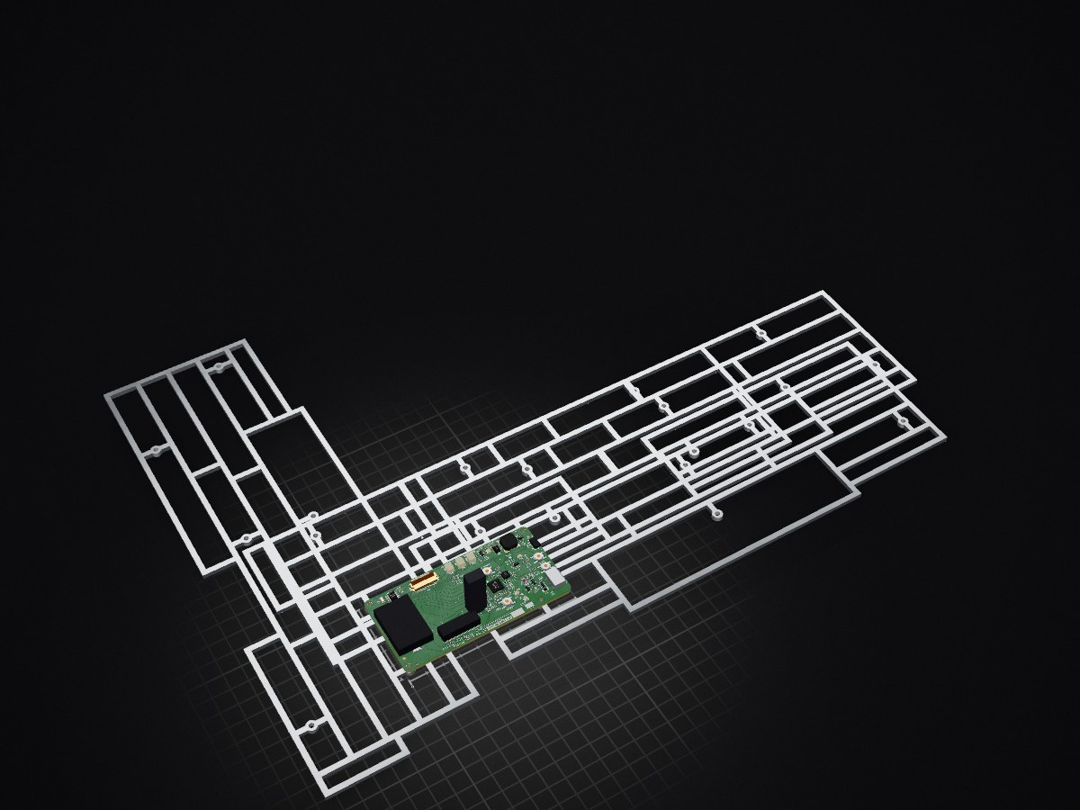
RP2040 RTC Module, highly compatible with JLCPCB's basic SMT components.
Clock pcb is an open-source printed circuit board by MitchellStride, from the MitchellStride/Hummingbird-RP2040-Clock-Module repository on GitHub. It is a 2-layer board of 100 × 50 mm with 124 parts on 92 nets, routed with 1,268 tracks and 279 vias.
It is built around the RP2040, DS1307Z+ and RT9080-33GJ5, with the SRV05-4, TS-1187A-B-A-B and AO3401A among its other parts. Its parts include 33 capacitors, 30 resistors, 7 connectors, 6 diodes and 5 ICs. It belongs with the lEDs and displays boards and the RP2040 boards of this library.







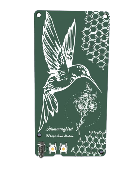
The Hummingbird RP2040 Clock Module is designed for crafting artisan clocks by pairing it with different clock faces. Its modular design allows this project to be shared across various display technologies.
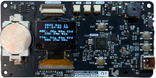
The test OLED above shows time, my age, and my time to death countdown based on my life expectancy.
The PCBA has arrived, and is working, it needed one bodge. FW is done.
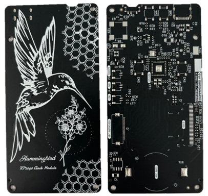
Clocks I plan to build using this module:
See: -> ./images/cost2.png
| Qty | Value | Footprint | References |
|---|---|---|---|
| 14 | 0.1u | Capacitor_SMD:C_0402_1005Metric | C3, C4, C5, C6, C7, C9, C10, C11, C14, C15, C19, C23, C25, C32 |
| 11 | 1u | Capacitor_SMD:C_0402_1005Metric | C2, C8, C18, C20, C21, C24, C26, C27, C29, C30, C33 |
| 9 | 10k | Resistor_SMD:R_0402_1005Metric | R4, R9, R20, R23, R25, R26, R27, R28, R29 |
| 7 | 1k | Resistor_SMD:R_0402_1005Metric | R1, R11, R15, R18, R19, R24, R30 |
| 4 | Mounting_Hole | MountingHole:MountingHole_2.7mm_M2.5 | H4, H5, H6, H7 |
| 4 | TS-1187A-B-A-B | stride_footprints:SW_SPST_TL3342_RT | SW2, SW3, SW4, SW5 |
| 3 | 4.7k | Resistor_SMD:R_0402_1005Metric | R13, R14, R21 |
| 3 | 4.7u | Capacitor_SMD:C_0402_1005Metric | C16, C17, C31 |
| 3 | 5V | Connector_JST:JST_SH_SM02B-SRSS-TB_1x02-1MP_P1.00mm_Horizontal | J4, J5, J6 |
| 3 | LOGO | silk:comb | G***, G***, G*** |
| 3 | Tooling_Hole_JLC | stride_footprints:JLC_Tooling_Hole | H1, H2, H3 |
| 2 | 0 | stride_footprints:R_0402_1005Metric_3pad | R16, R17 |
| 2 | 100k | Resistor_SMD:R_0402_1005Metric | R8, R10 |
| 2 | 10p | Capacitor_SMD:C_0402_1005Metric | C12, C13 |
| 2 | 10u | Capacitor_SMD:C_0402_1005Metric | C1, C22 |
| 2 | 22 | Resistor_SMD:R_0402_1005Metric | R6, R7 |
| 2 | 5.1k | Resistor_SMD:R_0402_1005Metric | R2, R3 |
| 2 | AO3401A | Package_TO_SOT_SMD:SOT-23 | Q1, Q2 |
| 2 | Fiducial | Fiducial:Fiducial_1mm_Mask2mm | FID1, FID2 |
| 2 | LED_G | LED_SMD:LED_0805_2012Metric | D3, D4 |
| 1 | 12V 3A | Fuse:Fuse_1206_3216Metric | F1 |
| 1 | 2.2k | Resistor_SMD:R_0402_1005Metric | R5 |
| 1 | 2.2u | Capacitor_SMD:C_0402_1005Metric | C28 |
| 1 | 2N7002 | Package_TO_SOT_SMD:SOT-23 | Q4 |
| 1 | 32.768kHz | Crystal:Crystal_SMD_3215-2Pin_3.2x1.5mm | Y2 |
| 1 | 330k | Resistor_SMD:R_0402_1005Metric | R31 |
| 1 | 3V3 | TestPoint:TestPoint_Pad_D1.0mm | TP7 |
| 1 | 5.6V | Diode_SMD:D_MiniMELF | D2 |
| 1 | 51 | Resistor_SMD:R_0402_1005Metric | R22 |
| 1 | 5V | TestPoint:TestPoint_Pad_D1.0mm | TP5 |
| 1 | AO3400A | Package_TO_SOT_SMD:SOT-23 | Q3 |
| 1 | CMT-8504-100-SMT-TR | Buzzer_Beeper:MagneticBuzzer_CUI_CMT-8504-100-SMT | BZ1 |
| 1 | CR2032 | stride_footprints:Q&J_CR2032-BS-6-1 | BT1 |
| 1 | DS1307Z+ | Package_SO:SOIC-8_3.9x4.9mm_P1.27mm | U5 |
| 1 | FFC 24 | Connector_FFC-FPC:Hirose_FH12-24S-0.5SH_1x24-1MP_P0.50mm_Horizontal | J3 |
| 1 | G*** | kibuzzard-68226193 | kibuzzard-68226193 |
| 1 | G*** | kibuzzard-682261BD | kibuzzard-682261BD |
| 1 | G*** | kibuzzard-682261F1 | kibuzzard-682261F1 |
| 1 | G*** | kibuzzard-682261D0 | kibuzzard-682261D0 |
| 1 | G*** | kibuzzard-68226263 | kibuzzard-68226263 |
| 1 | G*** | kibuzzard-68226165 | kibuzzard-68226165 |
| 1 | G*** | kibuzzard-682261A9 | kibuzzard-682261A9 |
| 1 | G*** | kibuzzard-682261E0 | kibuzzard-682261E0 |
| 1 | GND CLIP | stride_footprints:ronghe_RH-5016_C5199799 | TP4 |
| 1 | LED_Y | LED_SMD:LED_0805_2012Metric | D1 |
| 1 | LOGO | silk:hummingbird | G*** |
| 1 | LOGO | silk:flower | G*** |
| 1 | LOGO | silk:subtitle | G*** |
| 1 | LOGO | silk:title | G*** |
| 1 | OLED | stride_footprints:OLED-128O064D_edit_reverse_v2 | J7 |
| 1 | PROG | Connector:Tag-Connect_TC2030-IDC-NL_2x03_P1.27mm_Vertical | J2 |
| 1 | RP2040 | stride_footprints:QFN-56_EP_7x7_Pitch0.4mm | U1 |
| 1 | RST | TestPoint:TestPoint_Pad_D1.0mm | TP3 |
| 1 | RT9080-33GJ5 | Package_TO_SOT_SMD:SOT-23-5 | U3 |
| 1 | SRV05-4 | Package_TO_SOT_SMD:SOT-23-6 | U2 |
| 1 | SS14 | Diode_SMD:D_SMA | D6 |
| 1 | SSSS811101 | stride_footprints:SSSS811101 | SW1 |
| 1 | USB_C_Receptacle_USB2.0 | ftp:USB-C-16p | J1 |
| 1 | VBUS | TestPoint:TestPoint_Pad_D1.0mm | TP1 |
| 1 | W25Q64JV | Package_SON:WSON-8-1EP_4x4mm_P0.8mm_EP2.2x3mm | U4 |
| 1 | WS2812B-2020 | stride_footprints:WS2812B-2020 | D5 |
| 1 | XYDBPCNANF-12MHZ | Crystal:Crystal_SMD_3225-4Pin_3.2x2.5mm | Y1 |
MitchellStride/Hummingbird-RP2040-Clock-Module
RP2040 RTC Module, highly compatible with JLCPCB's basic SMT components.


Plastal-Bot-Builders/RoboCoreDocumentation
RoboCore is a classroom robot kit and coding platform, designed and built in Zambia by Plastal-Bot Builders (Lusaka).

misko/prompt2device
The separate vNext PCB skill and orchestrator package is available alongside the reference workflow below; existing projects keep their accepted toolchain until an explicit migration.


Takingo/Mypcb35
OmniCircuit AI is a local proof of concept for an autonomous PCB/PCBA design and manufacturing suite. The current implementation focuses on the ESP32-S3 + DWM3000 UWB Anchor example and establishes the architecture for:

It measures 100 × 50 mm and has 2 copper layers, 1.6 mm thick.
124 parts, built around the RP2040, DS1307Z+, RT9080-33GJ5 and SRV05-4. The full list of its parts is on this page, with links to each part's symbol and footprint where PCBKit's library has them.
From the MitchellStride/Hummingbird-RP2040-Clock-Module repository on GitHub, at the commit this page was made from: the board is pcb/v2/archive/clock_pcb.kicad_pcb and its schematic pcb/v1/2.kicad_sch. PCBKit opens the board in the browser, with nothing to install.
Its repository states no licence, so its author keeps all rights: ask MitchellStride before reusing the design.