2 layers68.9 × 23 mm
 Pioneer-Rocketry/Flight-Computer2
Pioneer Rocketry’s latest generation flight computer for high power, STM32-based avionics system designed for experimental high-power rockets.
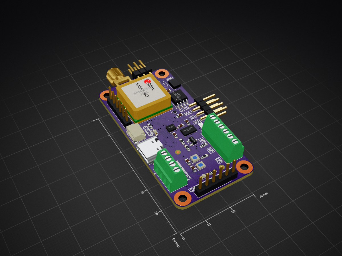
Flight Computer is an open-source printed circuit board by Pioneer-Rocketry, from the Pioneer-Rocketry/Flight-Computer repository on GitHub. It is a 6-layer board of 30 × 60 mm with 116 parts on 107 nets, routed with 731 tracks and 121 vias.
It is built around the SKY13453-385LF, SX1262IMLTRT and MMC5633NJL, with the W25Q128JVSIQ, LM1117MP-3.3 and LSM6DSV320X among its other parts. Its parts include 35 capacitors, 28 resistors, 9 ICs, 9 connectors and 7 inductors. It belongs with the STM32 boards of this library.


Pioneer Rocketry’s latest generation flight computer for high power, STM32-based avionics system designed for experimental high-power rockets. It provides state estimation, real-time telemetry, staging logic, and fully active control capabilities. This repository contains the firmware, test tools, and documentation for the system.
Before building this project, ensure you have the following tools installed and added to your system PATH:
winget install ezwinports.make or choco install make - Build system generator.arm-none-eabi-gcc).Install the following extensions within VS Code:
Clone the repository and open the folder in VS Code:
git clone --recurse-submodules https://github.com/Pioneer-Rocketry/Flight-Computer.gitYou can build the project using the status bar at the bottom or the Command Palette:
F7.Successful build output will create a Code.elf and Code.bin file in the ./Code/build/ directory.
Connect your STM32 board via ST-Link.
F5 to start debugging.C:\Dev\Project instead of C:\Users\My Name\Project).main.cpp is not being compiled, check CMakeLists.txt to ensure CXX is enabled and main.cpp is listed in the source files. If main.c is in the CDEF, remove it and delete the file.| Function | Component |
|---|---|
| Main MCU | STM32F446RE |
| High-G IMU (Accel + Gyro) | LSM6DSV32X |
| Magnetometer | MMC5603 |
| Barometer | MS5607-02BA03 |
| GPS | u-blox SAM-M8Q |
| Radio | LoRa SX1262 |
The firmware is written in modern C++, using HAL for low-level drivers and a modular class-based architecture for sensors, telemetry, and estimation modules.
HILT allows the flight computer to run full flight software using simulated sensor data.
This framework accelerates development and eliminates many failure modes before field testing.
Flight testing follows a staged, risk-managed approach:
Each successful flight unlocks the next feature set, ensuring safe and repeatable progress toward fully active control.
Flight-Computer/
├── Code/
│   ├── Core/
│   │   ├──Src/
│   │   └── Inc/
│   └── lib/
├── Datasheets/
└── PCB/| Qty | Value | Footprint | References |
|---|---|---|---|
| 19 | .1u | Capacitor_SMD:C_0603_1608Metric_Pad1.08x0.95mm_HandSolder | C101, C202, C203, C205, C206, C207, C209, C301, C302, C303, C304, C305, C401, C402, C501, C502 +3 |
| 8 | 10k | Resistor_SMD:R_0603_1608Metric_Pad0.98x0.95mm_HandSolder | R201, R203, R205, R406, R602, R604, R606, R613 |
| 7 | 5.1k | Resistor_SMD:R_0603_1608Metric_Pad0.98x0.95mm_HandSolder | R202, R204, R401, R402, R607, R609, R611 |
| 6 | 500 | Resistor_SMD:R_0603_1608Metric_Pad0.98x0.95mm_HandSolder | R404, R405, R501, R601, R603, R605 |
| 6 | Fiducial | Fiducial:Fiducial_1mm_Mask2mm | FID401, FID402, FID403, FID404, FID405, FID406 |
| 4 | 1k | Resistor_SMD:R_0603_1608Metric_Pad0.98x0.95mm_HandSolder | R101, R102, R403, R614 |
| 4 | M3 | MountingHole:MountingHole_2.7mm_Pad_TopBottom | H401, H402, H403, H404 |
| 4 | SL2302S | Package_TO_SOT_SMD:SOT-23-3 | Q401, Q601, Q602, Q603 |
| 3 | 3k | Resistor_SMD:R_0603_1608Metric_Pad0.98x0.95mm_HandSolder | R608, R610, R612 |
| 2 | 0R | Inductor_SMD:L_0603_1608Metric_Pad1.05x0.95mm_HandSolder | L506, L507 |
| 2 | 100p | Capacitor_SMD:C_0603_1608Metric_Pad1.08x0.95mm_HandSolder | C504, C512 |
| 2 | 2.2u | Capacitor_SMD:C_0603_1608Metric_Pad1.08x0.95mm_HandSolder | C204, C210 |
| 2 | 3.3p | Capacitor_SMD:C_0603_1608Metric_Pad1.08x0.95mm_HandSolder | C507, C510 |
| 2 | D | Package_TO_SOT_SMD:SOT-23 | D401, D405 |
| 2 | LED | LED_SMD:LED_0603_1608Metric_Pad1.05x0.95mm_HandSolder | D101, D403 |
| 2 | SW_Push | imported:SW_1TS026A | SW401, SW402 |
| 2 | WS2812B-2020 | LED_SMD:LED_WS2812B-2020_PLCC4_2.0x2.0mm | D402, D404 |
| 1 | 15n | Inductor_SMD:L_0603_1608Metric_Pad1.05x0.95mm_HandSolder | L505 |
| 1 | 15p | Capacitor_SMD:C_0603_1608Metric_Pad1.08x0.95mm_HandSolder | C513 |
| 1 | 15u | Inductor_SMD:L_0603_1608Metric_Pad1.05x0.95mm_HandSolder | L501 |
| 1 | 18p | Capacitor_SMD:C_0603_1608Metric_Pad1.08x0.95mm_HandSolder | C511 |
| 1 | 1p | Capacitor_SMD:C_0603_1608Metric_Pad1.08x0.95mm_HandSolder | C509 |
| 1 | 1u | Capacitor_SMD:C_0603_1608Metric_Pad1.08x0.95mm_HandSolder | C208 |
| 1 | 22n | Capacitor_SMD:C_0603_1608Metric_Pad1.08x0.95mm_HandSolder | C506 |
| 1 | 3.9n | Inductor_SMD:L_0603_1608Metric_Pad1.05x0.95mm_HandSolder | L504 |
| 1 | 32 MHz | Crystal:Crystal_SMD_2016-4Pin_2.0x1.6mm | Y501 |
| 1 | 33n | Inductor_SMD:L_0603_1608Metric_Pad1.05x0.95mm_HandSolder | L503 |
| 1 | 33p | Capacitor_SMD:C_0603_1608Metric_Pad1.08x0.95mm_HandSolder | C516 |
| 1 | 4.7p | Capacitor_SMD:C_0603_1608Metric_Pad1.08x0.95mm_HandSolder | C508 |
| 1 | 4.7u | Capacitor_SMD:C_0603_1608Metric_Pad1.08x0.95mm_HandSolder | C201 |
| 1 | 470n | Capacitor_SMD:C_0603_1608Metric_Pad1.08x0.95mm_HandSolder | C505 |
| 1 | 68n | Inductor_SMD:L_0603_1608Metric_Pad1.05x0.95mm_HandSolder | L502 |
| 1 | Buzzer | Buzzer:Buzzer_3mm | BZ401 |
| 1 | Conn_01x04 | Connector_JST:JST_SH_SM04B-SRSS-TB_1x04-1MP_P1.00mm_Horizontal | J408 |
| 1 | Conn_01x05_Pin | Connector_PinHeader_2.54mm:PinHeader_1x06_P2.54mm_Vertical | J401 |
| 1 | Conn_01x06_Pin | Connector_PinHeader_2.54mm:PinHeader_1x06_P2.54mm_Vertical | J403 |
| 1 | Conn_02x03_Counter_Clockwise | imported:EdgePinHeader_02x03 | J407 |
| 1 | Conn_02x04_Counter_Clockwise | imported:EdgePinHeader_02x04 | J406 |
| 1 | Conn_Coaxial | Connector_Coaxial:SMA_Samtec_SMA-J-P-H-ST-EM1_EdgeMount | J501 |
| 1 | FDN306P | Package_TO_SOT_SMD:SOT-23-3 | Q101 |
| 1 | LM1117MP-3.3 | Package_TO_SOT_SMD:SOT-223-3_TabPin2 | U101 |
| 1 | LOGO | imported:Logo | G*** |
| 1 | LSM6DSV320 | Package_LGA:LGA-14_3x2.5mm_P0.5mm_LayoutBorder3x4y | U302 |
| 1 | MMC5633NJL | Package_BGA:WLP-4_0.86x0.86mm_P0.4mm | U303 |
| 1 | MS5607-02BA | Package_LGA:LGA-8_3x5mm_P1.25mm | U304 |
| 1 | Resonator | imported:OSC_CSTNE8M00G52Z000R0 | Y201 |
| 1 | SAM-M8Q | RF_GPS:ublox_SAM-M8Q | U301 |
| 1 | SKY13453-385LF | imported:QFN_453-385LF_SKY | U502 |
| 1 | STM32F405RGTx | Package_QFP:LQFP-64_10x10mm_P0.5mm | U201 |
| 1 | SX1262IMLTRT | Package_DFN_QFN:QFN-24-1EP_4x4mm_P0.5mm_EP2.6x2.6mm | U501 |
| 1 | Screw_Terminal_01x04 | TerminalBlock_Phoenix:TerminalBlock_Phoenix_MPT-0,5-4-2.54_1x04_P2.54mm_Horizontal | J405 |
| 1 | Screw_Terminal_01x06 | TerminalBlock_Phoenix:TerminalBlock_Phoenix_MPT-0,5-6-2.54_1x06_P2.54mm_Horizontal | J404 |
| 1 | TBD | Capacitor_SMD:C_0603_1608Metric_Pad1.08x0.95mm_HandSolder | C517 |
| 1 | USB_C_Receptacle_USB2.0_16P | Connector_USB:USB_C_Receptacle_GCT_USB4105-xx-A_16P_TopMnt_Horizontal | J402 |
| 1 | W25Q128JVS | Package_SO:SOIC-8_5.3x5.3mm_P1.27mm | U202 |
| 1 | qwiic_Logo | imported:qwiic_5.5mm | G401 |

ShaneTWilliams/capstone
Remotely-operated quadcopter hardware, firmware and software


FBS93/STM32WLE5_RF_dongle
Compact RF dongle designed for wireless communication through USB.

It measures 30 × 60 mm and has 6 copper layers, 1.54 mm thick.
116 parts, built around the SKY13453-385LF, SX1262IMLTRT, MMC5633NJL and W25Q128JVSIQ. The full list of its parts is on this page, with links to each part's symbol and footprint where PCBKit's library has them.
From the Pioneer-Rocketry/Flight-Computer repository on GitHub, at the commit this page was made from: the board is PCB/Flight Computer.kicad_pcb and its schematic PCB/Flight Computer.kicad_sch. PCBKit opens the board in the browser, with nothing to install.
Its repository states no licence, so its author keeps all rights: ask Pioneer-Rocketry before reusing the design.