2 layers76 × 49 mm
Circuit Board V2
Pierowheelz/ac-vent-controller
ESP32-based controller for Aircon Vents with stepper motors.
11 parts

 Pierowheelz/ac-vent-controller
ESP32-based controller for Aircon Vents with stepper motors.
Circuit Board V2 is an open-source printed circuit board by Pierowheelz, from the Pierowheelz/ac-vent-controller repository on GitHub. It is a 2-layer board of 89.5 × 49 mm with 15 parts on 54 nets, routed with 205 tracks and 15 vias.
It is built around the TMC2209SILENTSTEPSTICK and TSR 1-2433E. Its parts include 6 ICs, 4 switches and 1 connector. It belongs with the robots and motor control boards and the ESP32 boards of this library.
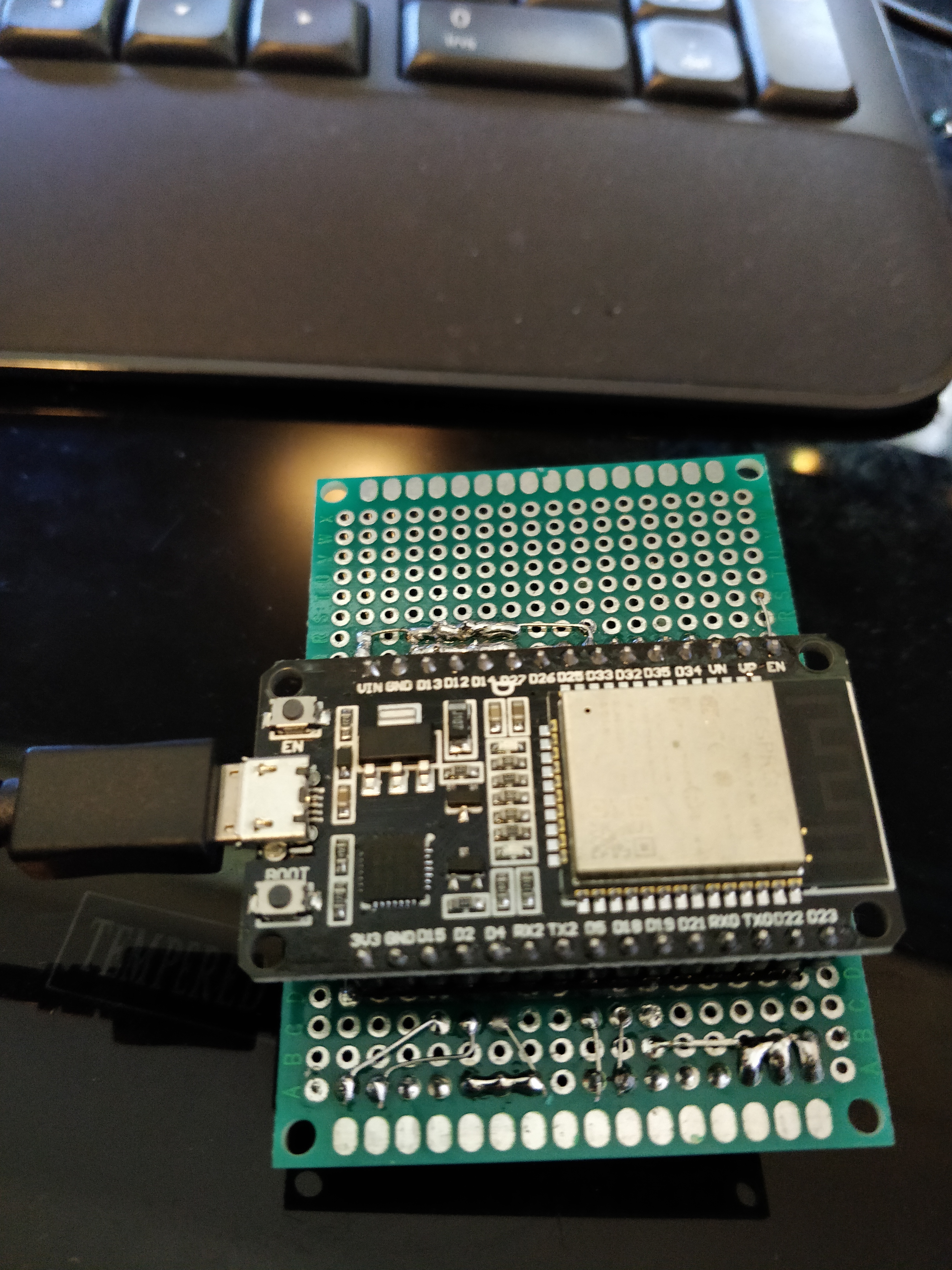
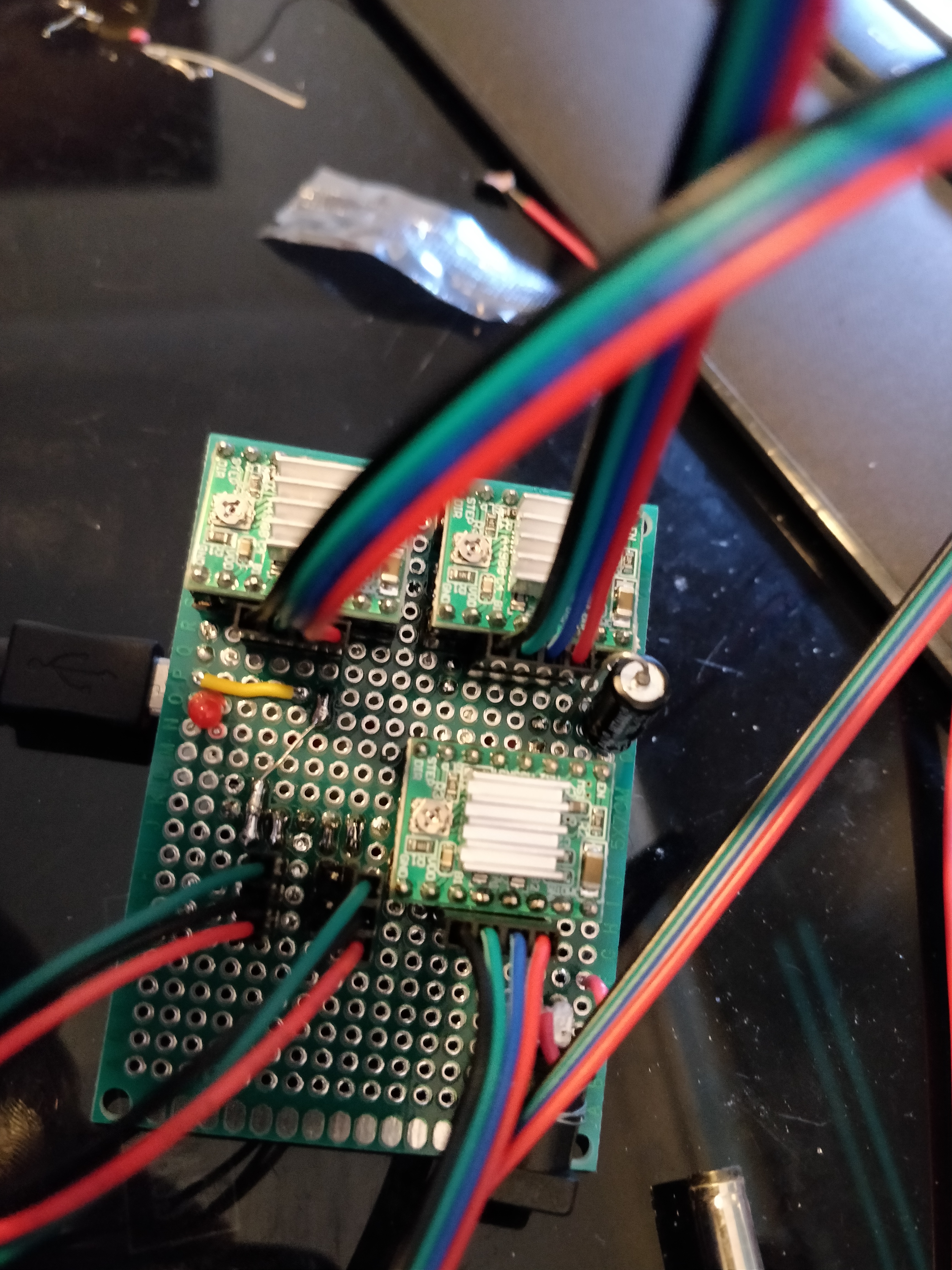
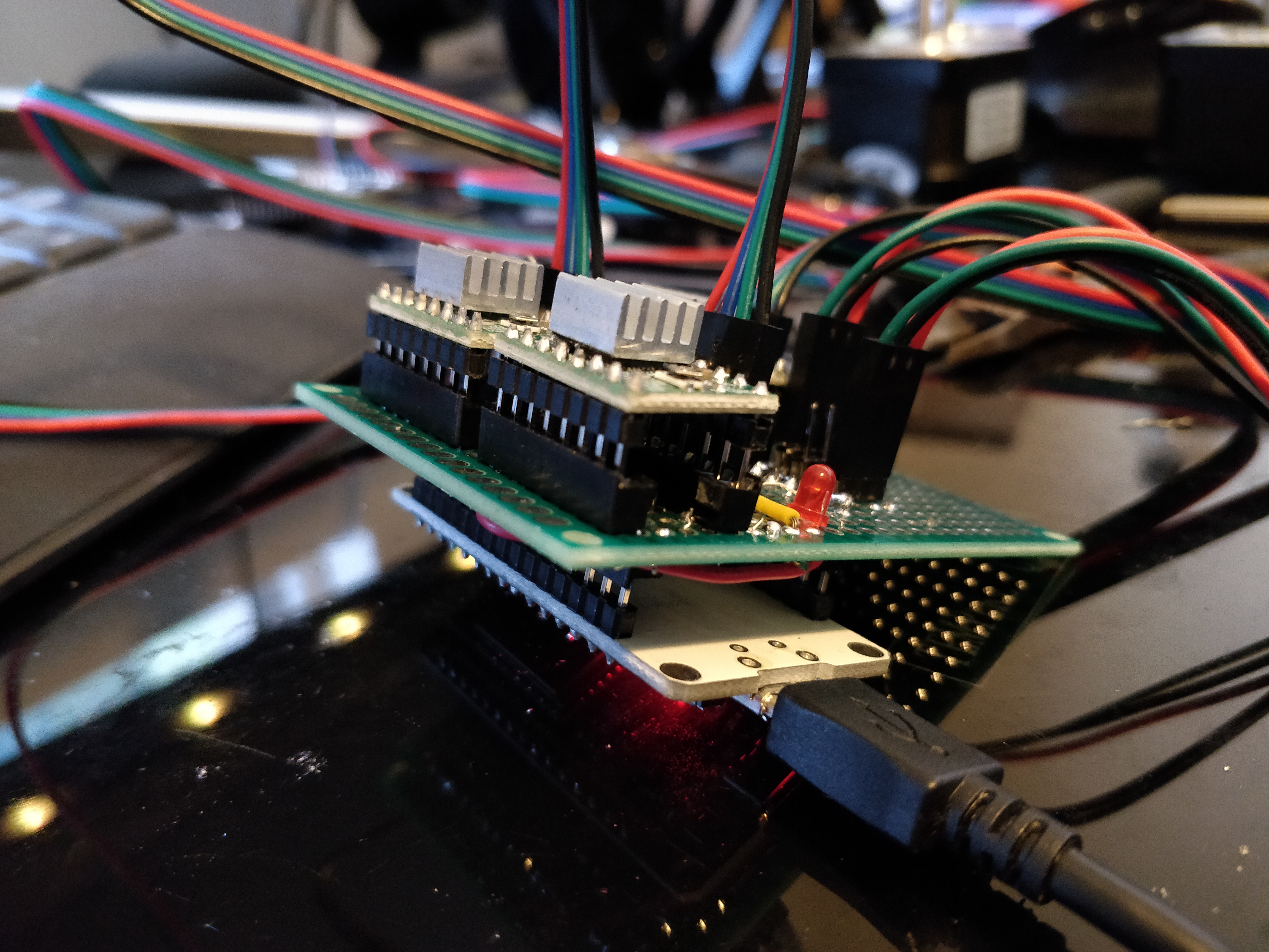
This project uses an ESP32-based controller, stepper motors, TMC2209 (or similar) drivers and endstop switches (from a 3d printer kit) to control the circular Air Conditioner vents used in many ducted HVAC systems. Each board can control up to 4 vents (leave the stepper header empty and tweak the /AC_Vent/config.h to control fewer vents). Multiple boards can be utilised to control more vents, or for vents too far from one board.
This project is part of a larger ecosystem, designed to enable automation of vents based on the room temperatures, along with an App for manual control.
Note: There is no security or authentication in this system. Do not open up the port in your Router! For use on your internal network only.
Get vents status: GET http://192.168.2.110/?&t=1
Sample return:
{
	"0": {
		"name": "Room #1",
		"pos": 30
	},
	"1": {
		"name": "Room #2",
		"pos": 60
	},
	"2": {
		"name": "Room #3",
		"pos": 100
	}
}
Open vent #1 to 100%: GET http://192.168.2.110/?a=6&t=1&m=0&d=100
Here a is the operating mode, where mode 6 corresponds to: open to ratio set by &d= (eg. ?d=050:open50%, ?d=000:close, ?d=100:open100%).
Also, t is the response type (1 = JSON).
And, m is the motor number (0-2).
The return format is identical to the 'get status' request.
Note: Some photos are from the prototype.
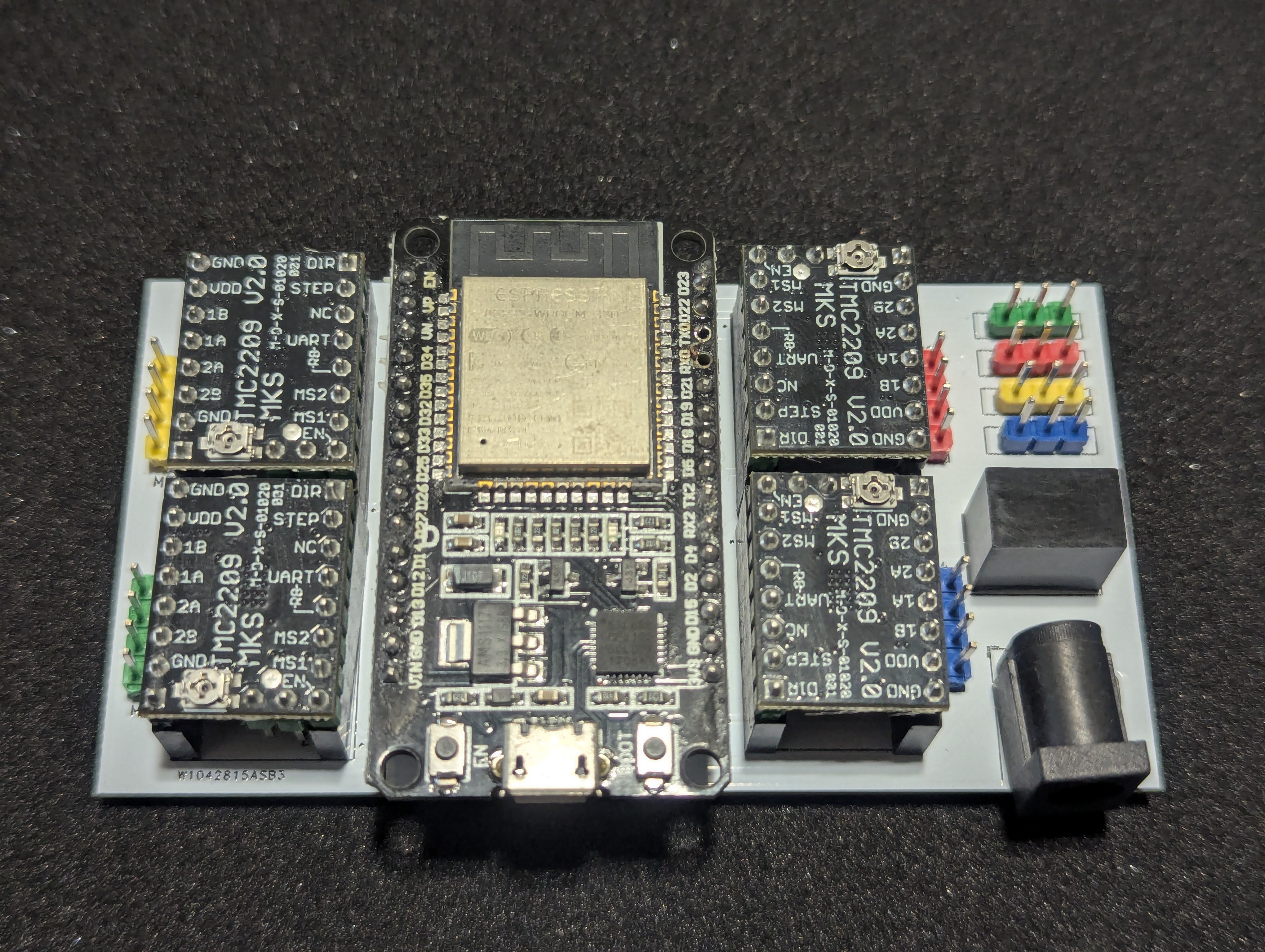
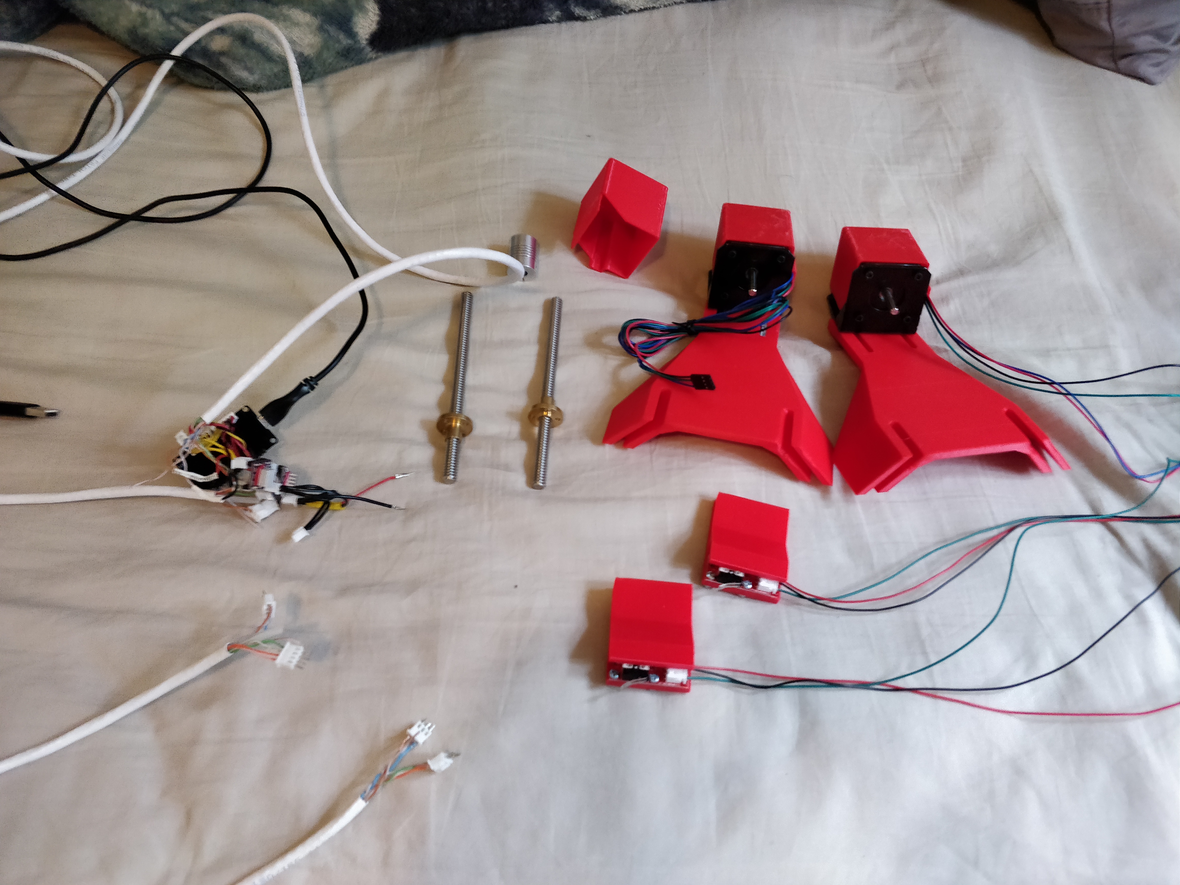
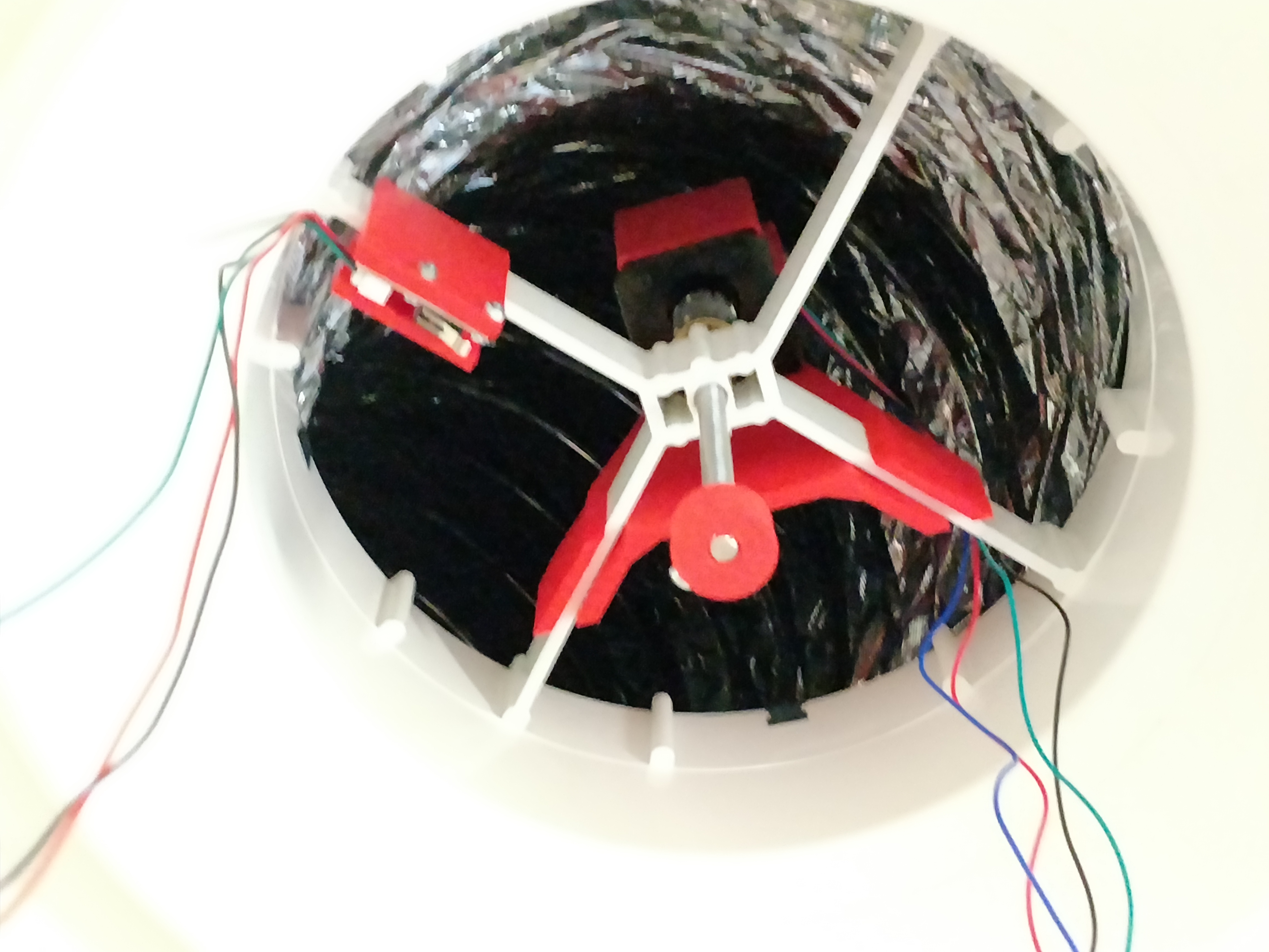
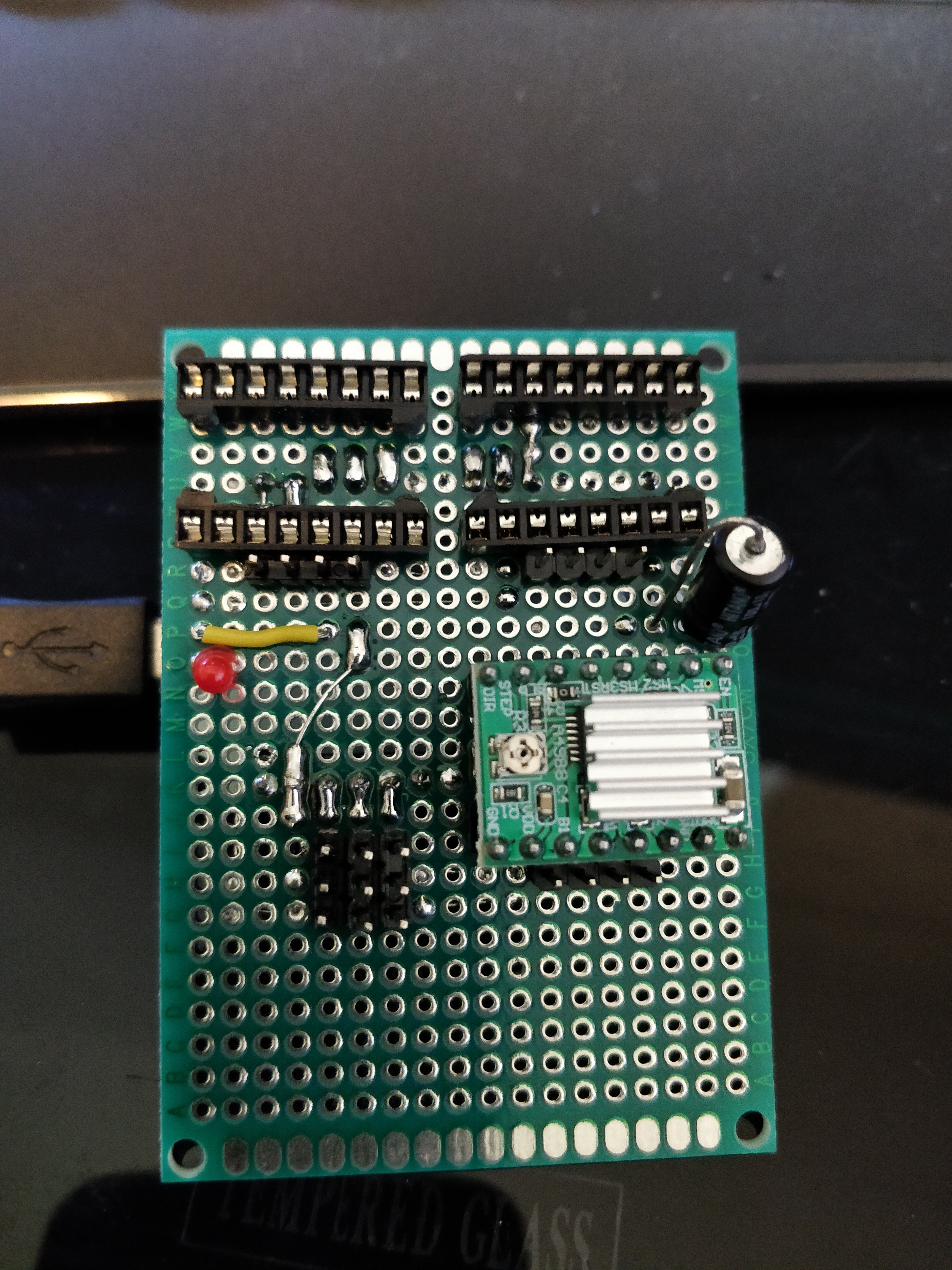
| Qty | Value | Footprint | References |
|---|---|---|---|
| 4 | SW_SPDT | Button_Switch_THT:SW_Slide-03_Wuerth-WS-SLTV_10x2.5x6.4_P2.54mm | SW1, SW2, SW3, SW4 |
| 4 | Stepper_Motor_bipolar | Connector_PinHeader_2.54mm:PinHeader_1x04_P2.54mm_Vertical | M1, M2, M3, M4 |
| 4 | TMC2209_SILENTSTEPSTICK | ESP32:MODULE_TMC2209_SILENTSTEPSTICK | U1, U2, U3, U6 |
| 1 | Barrel_Jack_MountingPin | Connector_BarrelJack:BarrelJack_Horizontal | J1 |
| 1 | DEVKIT_V1_ESP32-WROOM-32 | ESP32:MODULE_DEVKIT_V1_ESP32-WROOM-32 | U4 |
| 1 | TSR1-2433E | Converter_DCDC:Converter_DCDC_TRACO_TSR1-xxxxE_THT | U5 |
Pierowheelz/ac-vent-controller
ESP32-based controller for Aircon Vents with stepper motors.


rayanyahiaoui13/24PowerLEDsController
The goal of this system is to provide independent and precise control of a 24-LED matrix composed of high-power LEDs to independently illuminate 24 wells of a Greiner plate containing duckweed.

titio72/n2k_router_arduino
Integrated GPS, meteo, tachometer, and speed sensor for NMEA2000 networks

totaldesaster/SimpleFOC-Serial-Driver
Advanced dual BLDC driver based on the RP2350 and DRV8323S ICs, designed to be controlled from a trajectory controller over RS-485, RS-422 or TTL UART. Features a compact high power design with two stacked PCBs.

Unimakers/CDR-2027
Ce repo est un site de documentation réalisé par l'équipe des première et deusième années pré-ingénieur de l'école Unilasalle-Amiens, membre de l'association de robotique Unimaker, dans le cadre de leur participation à…

ManuelArgibay/Industrial-I-O-Controller
Industrial 24V I/O controller featuring protected high-side and low-side outputs, multiplexed analog and digital inputs, and MCU-based control.


Poky88/HAPCAN_Modul_RFID_CTECKA
This repository contains complete hardware and software resources for the development and implementation of a new extension module for the HAPCAN home automation system.
It measures 89.5 × 49 mm and has 2 copper layers, 1.6 mm thick.
15 parts, built around the TMC2209SILENTSTEPSTICK and TSR 1-2433E. The full list of its parts is on this page, with links to each part's symbol and footprint where PCBKit's library has them.
From the Pierowheelz/ac-vent-controller repository on GitHub, at the commit this page was made from: the board is Circuit Board V2/Circuit Board V2.kicad_pcb and its schematic Circuit Board V2/.history/Circuit Board V2.kicad_sch. PCBKit opens the board in the browser, with nothing to install.
Its repository states no licence, so its author keeps all rights: ask Pierowheelz before reusing the design.