6 layers39.5 × 39.5 mm
AD1 2.4G
Paschalis/UAV-TelemetryLink
Receiver and transmitter solution for GCS using ELRS, mLRS, and MAVLink for reliable telemetry and control.
55 parts11MIT

 Paschalis/UAV-TelemetryLink11
Receiver and transmitter solution for GCS using ELRS, mLRS, and MAVLink for reliable telemetry and control.
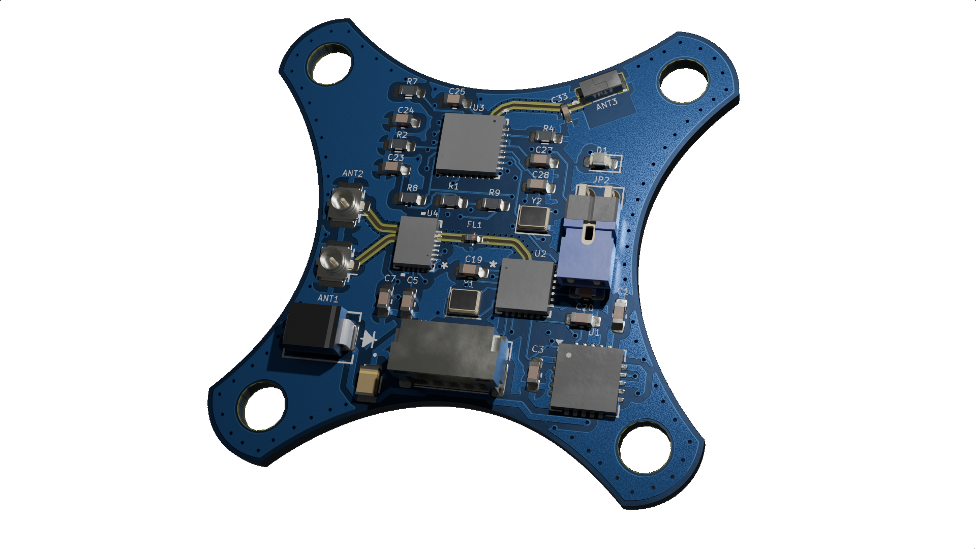
TD1 2.4G is an open-source printed circuit board by Paschalis, from the Paschalis/UAV-TelemetryLink repository on GitHub, published under the MIT licence. It is a 6-layer board of 39.5 × 39.5 mm with 63 parts on 92 nets, routed with 659 tracks and 172 vias.
It is built around the 2450LP14B100T, RFX2401C and SX1280IMLTRT, with the ESP32-PICO-D4, 2450FM07D0034T and AP2138N-2.8TRG1 among its other parts. Its parts include 29 capacitors, 9 ICs, 6 resistors, 2 connectors and 1 diode. It belongs with the ESP32 and RISC-V boards of this library.


Antenna Diversity (Basic diversity setup)
or

Click the icons to open iBOM or KiCanvas
| Reference | Value | Datasheet | Footprint | Qty | DNP |
|---|---|---|---|---|---|
| AE1 | Antenna | ~ | RF_Antenna:Texas_SWRA117D_2.4GHz_Right | 1 | |
| ANT1, ANT2 | Conn_Coaxial | ~ | Connector_Coaxial:U.FL_Hirose_U.FL-R-SMT-1_Vertical | 2 | |
| C1, C30, C32 | 10uF | ~ | Capacitor_SMD:C_0805_2012Metric_Pad1.18x1.45mm_HandSolder,ECASD40J106M055K00:ECASD40J106M055K00 | 3 | |
| C2 | 1uF | ~ | Capacitor_SMD:C_0805_2012Metric_Pad1.18x1.45mm_HandSolder | 1 | |
| C3 | 47uF | ~ | Capacitor_SMD:C_0805_2012Metric_Pad1.18x1.45mm_HandSolder | 1 | |
| C4 | 2.2uF | ~ | Capacitor_SMD:C_0805_2012Metric_Pad1.18x1.45mm_HandSolder | 1 | |
| C5, C6, C21, C22 | 10pF | ~ | Capacitor_SMD:C_0805_2012Metric_Pad1.18x1.45mm_HandSolder | 4 | |
| C7, C16, C17, C23, C24, C25, C26, C27, C28, C29 | 100nF | ~ | Capacitor_SMD:C_0805_2012Metric_Pad1.18x1.45mm_HandSolder | 10 | |
| C18 | 470nF | ~ | Capacitor_SMD:C_0805_2012Metric_Pad1.18x1.45mm_HandSolder | 1 | |
| C19, C20 | 10nF | ~ | Capacitor_SMD:C_0805_2012Metric_Pad1.18x1.45mm_HandSolder | 2 | |
| C31 | 0.1uF | ~ | Capacitor_SMD:C_0805_2012Metric_Pad1.18x1.45mm_HandSolder | 1 | |
| D1 | LED | ~ | LED_SMD:LED_0805_2012Metric_Pad1.15x1.40mm_HandSolder | 1 | |
| FL1 | 2450FM07D0034T | Datasheet | 2450FM07D0034T:2450FM07D0034T | 1 | |
| J1 | Conn_01x04_Socket | ~ | Connector_Harwin:Harwin_M20-89004xx_1x04_P2.54mm_Horizontal | 1 | |
| J3 | Conn_01x04_Pin | ~ | Connector_JST:JST_GH_SM04B-GHS-TB_1x04-1MP_P1.25mm_Horizontal | 1 | |
| JP1 | Jumper_2_Bridged | ~ | TestPoint:TestPoint_2Pads_Pitch2.54mm_Drill0.8mm | 1 | |
| R1 | 2.2K | ~ | Resistor_SMD:R_0805_2012Metric_Pad1.20x1.40mm_HandSolder | 1 | |
| R2, R3, R7, R8, R10 | 10K | ~ | Resistor_SMD:R_0805_2012Metric_Pad1.20x1.40mm_HandSolder | 5 | |
| R4 | 12K | ~ | Resistor_SMD:R_0805_2012Metric_Pad1.20x1.40mm_HandSolder | 1 | |
| R5 | 0 | ~ | Resistor_SMD:R_0805_2012Metric_Pad1.20x1.40mm_HandSolder | 1 | |
| R6 | 1K | ~ | Resistor_SMD:R_0805_2012Metric_Pad1.20x1.40mm_HandSolder | 1 | |
| R9 | 1.2K | ~ | Resistor_SMD:R_0805_2012Metric_Pad1.20x1.40mm_HandSolder | 1 | |
| U1 | TPS7A4701xRGW | Datasheet | Package_DFN_QFN:Texas_RGW0020A_VQFN-20-1EP_5x5mm_P0.65mm_EP3.15x3.15mm_ThermalVias | 1 | |
| U2 | SX1280IMLTRT | SX1280IMLTRT | SX1280IMLTRT:QFN24_4X4_SEM | 1 | |
| U3 | ESP8285H16 | ESP8285H16 | ESP8285H16:QFN32_5X5_EXP | 1 | |
| U4 | SE2431L-R | SE2431L-R | SE2431L-R:SE2431L_SKY | 1 | |
| Y1 | 52MHz | ~ | Crystal:Crystal_SMD_2016-4Pin_2.0x1.6mm | 1 | |
| Y2 | 26MHz | ~ | Crystal:Crystal_SMD_2016-4Pin_2.0x1.6mm | 1 |
| Qty | Value | Footprint | References |
|---|---|---|---|
| 8 | 100nF | Capacitor_SMD:C_0603_1608Metric_Pad1.08x0.95mm_HandSolder | C4, C8, C9, C13, C22, C24, C25, C27 |
| 6 | 10K | Resistor_SMD:R_0603_1608Metric_Pad0.98x0.95mm_HandSolder | R1, R2, R3, R4, R5, R6 |
| 5 | 1uF | Capacitor_SMD:C_0603_1608Metric_Pad1.08x0.95mm_HandSolder | C2, C15, C19, C28, C29 |
| 4 | hole1, hole2, Hole3, Hole4 | ||
| 4 | 10nF | Capacitor_SMD:C_0603_1608Metric_Pad1.08x0.95mm_HandSolder | C5, C6, C10, C11 |
| 4 | 220pF | Capacitor_SMD:C_0603_1608Metric_Pad1.08x0.95mm_HandSolder | C14, C16, C17, C18 |
| 2 | 2450FM07D0034T | 2450FM07D0034T:2450FM07D0034T | FL1, FL2 |
| 2 | 2450LP14B100 | 2450LP14B100:CHIP_SMD_1P6XP8_JOD | U5, U7 |
| 2 | 470nF | Capacitor_SMD:C_0603_1608Metric_Pad1.08x0.95mm_HandSolder | C7, C12 |
| 2 | Conn_Coaxial | Connector_Coaxial:U.FL_Hirose_U.FL-R-SMT-1_Vertical | ANT1, ANT2 |
| 2 | RFX2401C | RFX2401C:RFX2401C_SKY | U4, U6 |
| 2 | SX1280IMLTRT | SX1280IMLTRT:QFN24_4X4_SEM | U2, U3 |
| 1 | 0.1uF | Capacitor_SMD:C_0603_1608Metric_Pad1.08x0.95mm_HandSolder | C20 |
| 1 | 1.5pF | Capacitor_SMD:C_01005_0402Metric_Pad0.57x0.30mm_HandSolder | C33 |
| 1 | 10uF | Capacitor_SMD:C_0603_1608Metric_Pad1.08x0.95mm_HandSolder | C1 |
| 1 | 10uF | ECASD40J106M055K00:ECASD40J106M055K00 | C23 |
| 1 | 15u | Inductor_SMD:L_0805_2012Metric | L1 |
| 1 | 1nF | Capacitor_SMD:C_0603_1608Metric_Pad1.08x0.95mm_HandSolder | C26 |
| 1 | 47uF | Capacitor_SMD:C_0603_1608Metric_Pad1.08x0.95mm_HandSolder | C3 |
| 1 | 52Mhz TCXO | Crystal:Crystal_SMD_2016-4Pin_2.0x1.6mm | Y3 |
| 1 | AP2138N-2.8TRG1 | Package_TO_SOT_SMD:SOT-23 | U11 |
| 1 | Conn_01x04_Pin | Connector_JST:JST_GH_SM04B-GHS-TB_1x04-1MP_P1.25mm_Horizontal | J1 |
| 1 | Conn_01x04_Socket | Connector_Harwin:Harwin_M20-89004xx_1x04_P2.54mm_Horizontal | J2 |
| 1 | ESP32-PICO-D4 | Package_DFN_QFN:QFN-48-1EP_7x7mm_P0.5mm_EP5.1x5.1mm_ThermalVias | U8 |
| 1 | Jumper_2_Small_Bridged | TestPoint:TestPoint_2Pads_Pitch2.54mm_Drill0.8mm | JP1 |
| 1 | LOGO | logo:logo | G*** |
| 1 | LOGO | LOGO | G*** |
| 1 | MF-PSMF020X-2 | ul_MF-PSMF020X-2:FUSE_F020X_BRN | F1 |
| 1 | SMBJ60A | ul_SMBJ60A:SMBJSeries_LTF | CR1 |
| 1 | TPS7A4701xRGW | Package_DFN_QFN:Texas_RGW0020A_VQFN-20-1EP_5x5mm_P0.65mm_EP3.15x3.15mm_ThermalVias | U1 |
| 1 | W3008 | W3008:ANTENNA_W3008 | ANT3 |
| 1 | WS2812B-2020 | LED_SMD:LED_WS2812B-2020_PLCC4_2.0x2.0mm | D1 |
Paschalis/UAV-TelemetryLink
Receiver and transmitter solution for GCS using ELRS, mLRS, and MAVLink for reliable telemetry and control.

Paschalis/UAV-TelemetryLink
Receiver and transmitter solution for GCS using ELRS, mLRS, and MAVLink for reliable telemetry and control.

Paschalis/UAV-TelemetryLink
Receiver and transmitter solution for GCS using ELRS, mLRS, and MAVLink for reliable telemetry and control.

Paschalis/UAV-TelemetryLink
Receiver and transmitter solution for GCS using ELRS, mLRS, and MAVLink for reliable telemetry and control.

Paschalis/fc-plus-sensor-module
FC Plus is a modular add-on board for UAV flight controllers, providing advanced telemetry, GPS, object avoidance (ToF, Sonar, IR), and LED indicators for status feedback.

AnyLeaf/elrs-hardware
This repo contains open source hardware information for AnyLeaf ELRS receivers

bastian2001/Kolibri-FC-Hardware
Hardware for the Kolibri Flight Controller. 30mm/20mm FC with RP2350 + ELRS onboard

maholli/sx1280-breakout
breakout board for Semtech SX1280 LoRa radio compatible with RFM9x footprints


LongDo1902/STM32_Drone
Developing quadcopter from scratch including stm32 programing and self-built flight controller PCB.


It measures 39.5 × 39.5 mm and has 6 copper layers, 1.53 mm thick.
63 parts, built around the 2450LP14B100T, RFX2401C, SX1280IMLTRT and ESP32-PICO-D4. The full list of its parts is on this page, with links to each part's symbol and footprint where PCBKit's library has them.
From the Paschalis/UAV-TelemetryLink repository on GitHub, at the commit this page was made from: the board is Receivers and Transmitters/Receivers/True Antenna Diversity/ExpressLRS_2.4GHz/TD1_2.4G/TD1_2.4G.kicad_pcb and its schematic Receivers and Transmitters/Receivers/Antenna Diversity/ExpressLRS_2.4GHz/AD1_2.4G/AD1_2.4G.kicad_sch. PCBKit opens the board in the browser, with nothing to install.
Its repository publishes it under the MIT licence: you may reuse it on that licence's terms (keep the author's notice, and for a copyleft licence share your changes alike).