
2 layers33.7 × 97.8 mm
HAN ESP TSS721
UtilitechAS/amsreader-firmware
ESP8266 and ESP32 compatible firmware to read, interpret and publish data to MQTT from smart electrical meters, both DLMS and DSMR is supported
29 parts470
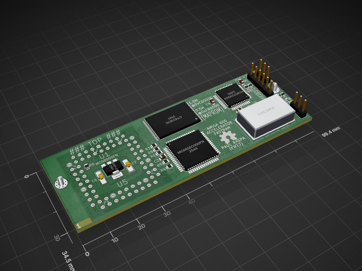
 PR77/A600_ACCEL_RAM35
Amiga 600 Accelerator And RAM Expansion
A600 ACCEL RAM is an open-source printed circuit board by PR77, from the PR77/A600_ACCEL_RAM repository on GitHub, published under the GPL-3.0 licence. It is a 4-layer board of 99.4 × 34.5 mm with 33 parts on 99 nets, routed with 1,195 tracks and 196 vias.
It is built around the LM1117-3.3. Its parts include 10 resistors, 9 capacitors, 5 ICs, 3 connectors and 2 diodes. It belongs with the retro computing and games and fPGA and programmable logic boards and the FPGA and CPLD boards of this library.
Design attempt for an Amiga 600 over CPU (PLCC) 68000 Accelerator including 1.5MB FastRAM (... or is it SlowRAM) and 0.5MB MapROM support.
This design has not been compliance tested and will not be. It may cause damage to your A600. I take no responsibility for this. I accept no responsibility for any damage to any equipment that results from the use of this design and its components. IT IS ENTIRELY AT YOUR OWN RISK!
The main purpose of this design was to develop a simple, affordable and efficient Accelerator, FastRAM and MapROM support device for the Amiga 600. The main components of the design and the CPU (MC68SEC000), CPLD (9572) and SRAM (CY62167G). There are the odd LEDs for status and some IO Pins for currently unplanned additions. As discovered in my A500 Accelerator the MC68SEC000 can be aggressively clocked and this design does not detour from that.
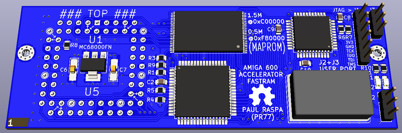
Nice 3D model:
Installed on A600 Motherboard:
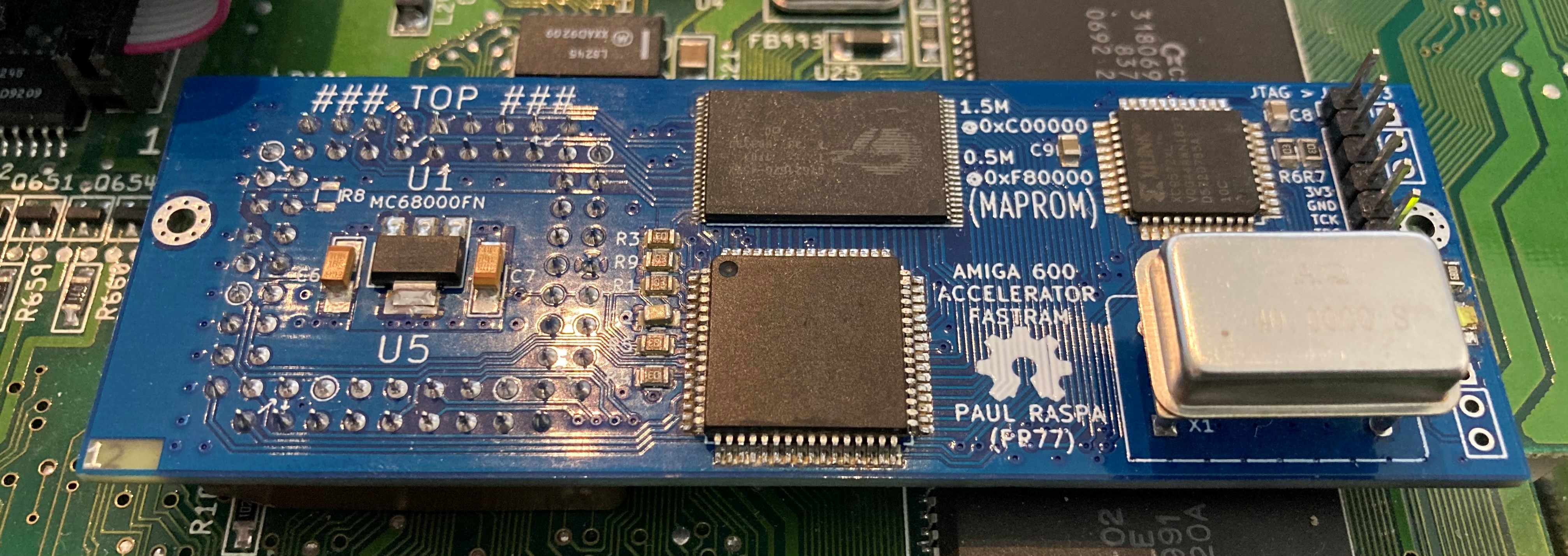
Mounting holes on the Accelerator PCB match with the HDD cradle and accommodate a M2 screw to provide stress relief for the PLCC68 socket. SukkoPera has a great guide on how to prepare the PLCC68 socket as some small modifications are required. His how to guide is linked here;
https://github.com/SukkoPera/OpenAmiga600FastRamExpansion/blob/master/SocketRework.md
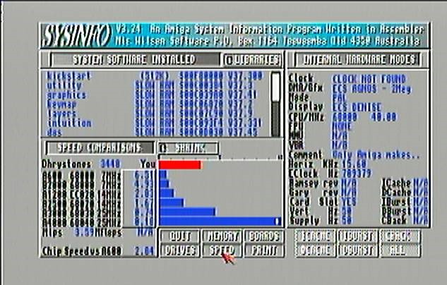
Testing has shown that the A600 system is fairly stable at 40MHz. Slower crystals can be used if stability is an issue (let me know if you run into issues). I've had the classic Amiga Juggler running for 48 Hours without any issues. Classic SysInfo shows @ 40MHz (with MapROM active);
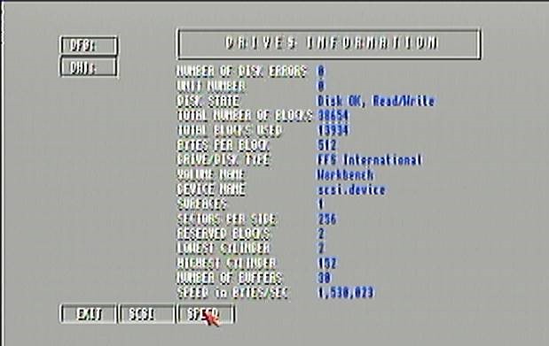
IDE (via GAYLE's scsi.device) also shows a nice speed improvement with a CF Card:
For those wanting to build their own hardware, here is the BOM;
| Reference(s) | Value | Footprint |
|---|---|---|
| C1 | 100n | Capacitors_SMD:C_0805 |
| C2 | 100n | Capacitors_SMD:C_0805 |
| C3 | 100n | Capacitors_SMD:C_0805 |
| C4 | 100n | Capacitors_SMD:C_0805 |
| C6 | 10u | Capacitors_Tantalum_SMD:CP_Tantalum_Case-R_EIA-2012-12_Hand |
| C7 | 10u | Capacitors_Tantalum_SMD:CP_Tantalum_Case-R_EIA-2012-12_Hand |
| C8 | 100n | Capacitors_SMD:C_0805 |
| C9 | 100n | Capacitors_SMD:C_0805 |
| C10 | 100n | Capacitors_SMD:C_0805 |
| D1 | LED | LEDs:LED_0805 |
| D2 | LED | LEDs:LED_0805 |
| J1 | JTAG | Connector:Conn_01x06_Male","Pin_Headers:Pin_Header_Straight_1x06_Pitch2.54mm |
| J2 (not loaded) | SPARE1 | Connector:Conn_01x03_Male","Pin_Headers:Pin_Header_Straight_1x03_Pitch2.54mm |
| J3 (not loaded) | SPARE2 | Connector:Conn_01x03_Male","Pin_Headers:Pin_Header_Straight_1x03_Pitch2.54mm |
| R1 | 10K | Resistors_SMD:R_0805 |
| R3 | 10K | Resistors_SMD:R_0805 |
| R4 | 10K | Resistors_SMD:R_0805 |
| R5 | 10K | Resistors_SMD:R_0805 |
| R6 | 10K | Resistors_SMD:R_0805 |
| R7 | 10K | Resistors_SMD:R_0805 |
| R8 (not loaded) | 10K | Resistors_SMD:R_0805 |
| R9 | 10K | Resistors_SMD:R_0805 |
| R10 | 680R | Resistors_SMD:R_0805 |
| R11 | 680R | Resistors_SMD:R_0805 |
| U1 | SOCKET | PLCC-68_THT-SocketUpsideDown |
| U2 | MC68SEC000 | Housings_QFP:LQFP-64_14x14mm_Pitch0.8mm |
| U3 | CY62167G | Housings_SSOP:TSOP-I-48_18.4x12mm_Pitch0.5mm |
| U4 | XC9572VQ44 | Housings_QFP:LQFP-44_10x10mm_Pitch0.8mm |
| U5 | LM1117-3.3 | TO_SOT_Packages_SMD:SOT-223-3_TabPin2 |
| X1 | CXO_DIP14 | Oscillators:Oscillator_DIP-14 |
Regarding the CPU, I purchased from here (I get nothing from this. The parts I received were new and legitimate so I wanted to share the source);
2 LED indicators are present:
To simplify the design and keep the CPLD pin count down, I decided not to use traditional FastRAM, rather use SlowRAM which is automatically mapped by the Amiga if valid memory is detected between 0xC00000 - 0xD7FFFF. In this range 1.5MB is available. In this memory range, the Accelerator performs the address decoding and subsequent /DTACK cycle. /AS is not asserted on the Amiga, thus the speed of memory cycles in this range is equivalent to that of FastRAM.
Of the 2MB RAM available, 1.5MB is allocated to SlowRAM and the remainder is allocated for MapROM. MapROM simply works by routing write cycle to 0xF8xxxx directly to the Accelerators RAM. Once enough write cycles are detected (262144 WORD writes), the MapROM write status is latched. After a subsequent Reset, memory accesses to 0xF8xxxx are directly routed to the Accelerators RAM (at full speed) and /AS is not asserted on the Amiga.
To deactive MapROM, simply hold down CTRL-A-A for 1 second and it will be deactivated. A different image could then be loaded. Note, once an image is loaded it needs to be deactivated again before a different image can be used. DiagROM images could also be used - helpful to avoid swapping out the physical ROM chip.
| Qty | Value | Footprint | References |
|---|---|---|---|
| 8 | 10K | Resistors_SMD:R_0805 | R1, R3, R4, R5, R6, R7, R8, R9 |
| 7 | 100n | Capacitors_SMD:C_0805 | C1, C2, C3, C4, C8, C9, C10 |
| 2 | 10u | Capacitors_Tantalum_SMD:CP_Tantalum_Case-R_EIA-2012-12_Hand | C6, C7 |
| 2 | 680R | Resistors_SMD:R_0805 | R10, R11 |
| 2 | LED | LEDs:LED_0805 | D1, D2 |
| 2 | MountingHole_Pad | Mounting_Holes:MountingHole_2.2mm_M2_Pad_Via | H1, H2 |
| 1 | CXO_DIP14 | Oscillators:Oscillator_DIP-14 | X1 |
| 1 | CY62167G | Housings_SSOP:TSOP-I-48_18.4x12mm_Pitch0.5mm | U3 |
| 1 | JTAG | Pin_Headers:Pin_Header_Straight_1x06_Pitch2.54mm | J1 |
| 1 | LM1117-3.3 | TO_SOT_Packages_SMD:SOT-223-3_TabPin2 | U5 |
| 1 | MC68000FN | A600_ACCEL_RAM:PLCC-68_THT-SocketUpsideDown | U1 |
| 1 | MC68SEC000FN | Housings_QFP:LQFP-64_14x14mm_Pitch0.8mm | U2 |
| 1 | OSHW | Symbols:OSHW-Symbol_6.7x6mm_SilkScreen | LOGO1 |
| 1 | SPARE1 | Pin_Headers:Pin_Header_Straight_1x03_Pitch2.54mm | J2 |
| 1 | SPARE2 | Pin_Headers:Pin_Header_Straight_1x03_Pitch2.54mm | J3 |
| 1 | XC9572VQ44 | Housings_QFP:LQFP-44_10x10mm_Pitch0.8mm | U4 |
UtilitechAS/amsreader-firmware
ESP8266 and ESP32 compatible firmware to read, interpret and publish data to MQTT from smart electrical meters, both DLMS and DSMR is supported

karawin/Ka-Radio
A wifi webradio with only low cost boards ESP8266 and VS1053 by Jp Cocatrix


doudar/SmartSpin2k
Transform your spin bike into a Smart Trainer!

plinkysynth/plinky_public
a public release of the plinky sw and hw

eddyem/stm32samples
Code samples and ready projects based on bare-metal STM32


It measures 99.4 × 34.5 mm and has 4 copper layers, 1.6 mm thick.
33 parts, built around the LM1117-3.3. The full list of its parts is on this page, with links to each part's symbol and footprint where PCBKit's library has them.
From the PR77/A600_ACCEL_RAM repository on GitHub, at the commit this page was made from: the board is Hardware/A600_ACCEL_RAM.kicad_pcb. PCBKit opens the board in the browser, with nothing to install.
Its repository publishes it under the GPL-3.0 licence: you may reuse it on that licence's terms (keep the author's notice, and for a copyleft licence share your changes alike).