2 layers150.2 × 80.4 mm
Esquema
CactusRockets/Weiss_Placas
Aqui colocaremos as placas do projeto, arquivos vindos do EAGLE e KiCAD
23 parts1

 OxMarco/ethereum-lora10
A long-range low-power radio interface for Ethereum nodes
ADAPTER PCB is an open-source printed circuit board by OxMarco, from the OxMarco/ethereum-lora repository on GitHub, published under the MIT licence. It is a 2-layer board of 20 × 47.3 mm with 17 parts on 19 nets, routed with 73 tracks and 21 vias.
It is built around the E22-400T30D, CH340X and 917-181A202ED60200. Its parts include 5 capacitors, 2 ICs, 1 resistor, 1 diode and 1 connector. It belongs with the radio and wireless and interfaces and adapters boards of this library.


Ethereum LoRa is a project aimed at adding a LoRa radio interface to Ethereum nodes. By doing so, it becomes possible to query a node with JSON-RPC commands even in locations where Wi-Fi or cellular connectivity is absent. This enhancement allows Ethereum-based services to run in rural or underdeveloped areas of the world, fostering crypto adoption.
The LoRa Communication System is an innovative project designed to facilitate seamless and efficient communication using the LoRa protocol. Aimed at establishing a reliable medium for data transmission even in challenging conditions, our solution stands as a testament to the powerful blend of software ingenuity and hardware capabilities. Whether it's for remote sensing applications, IoT devices, or any scenario where traditional connectivity might falter, our system ensures that your data reaches its destination.
The software interfaces with the Ethereum node and the LoRa E22 module, allowing bi-directional communication. When the system starts, it sets up the LoRa module with specific configurations. Users can input JSON payloads, which are then sent via the LoRa interface to an Ethereum node. The system also listens for incoming messages from the Ethereum node, which can then be parsed and presented to the user.
At its core, our system relies on the LoRa (Long Range) protocol, a patented digital wireless data communication technology. Through a combination of software controllers and hardware integrations, the system listens for incoming LoRa messages and parses them for further processing. Depending on the message type—whether it's a handshake or a request—the controller can efficiently interpret and respond to the data.
We've designed a modular approach, with a main driver program that leverages two key components: the ConfigManager and LoRaController. The ConfigManager handles configuration retrieval while the LoRaController manages the setup, listening, and sending of LoRa messages. When data is received, it's parsed based on its message type and, if it's a request, further extracted to ensure clean and valid JSON content.
git clone <repository_url>pip install -r requirements.txtLORA_CHIP_MODEL, SERIAL_PORT, etc.).python client.pypython server.pyThe BOM is very basic, consisting of a LoRa UART module and a simple PCB TTL-to-UART adapter.
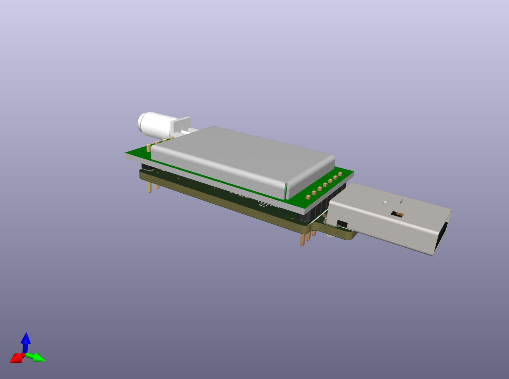 Pins at the bottom of the PCB allow users to upgrade the firmware or select a different working mode, for instance to support re-broadcasting, a form of basic mesh networking.
A big thanks goes to the Ethereum Foundation for sponsoring this project under their "Run a Node" program.
| Qty | Value | Footprint | References |
|---|---|---|---|
| 4 | TestPoint | TestPoint:TestPoint_Pad_D1.0mm | TP1, TP2, TP3, TP4 |
| 3 | 0.1uF | Capacitor_SMD:C_0603_1608Metric | C1, C3, C4 |
| 1 | 10uF | Capacitor_SMD:C_0805_2012Metric | C2 |
| 1 | 1A | Fuse:Fuse_0805_2012Metric | F1 |
| 1 | 1k | Resistor_SMD:R_0603_1608Metric | R3 |
| 1 | 47uF | Capacitor_Tantalum_SMD:CP_EIA-3528-15_AVX-H | C5 |
| 1 | 917-181A202ED60200 | FOOTPRINTS:USB-A-TH_917-181A202ED60201 | J1 |
| 1 | CH340X | Package_SO:MSOP-10_3x3mm_P0.5mm | U2 |
| 1 | E22-400T30D | FOOTPRINTS:COMM-TH_E22-400T30D | U1 |
| 1 | M0 | Connector_PinHeader_2.54mm:PinHeader_1x02_P2.54mm_Horizontal | JP1 |
| 1 | M1 | Connector_PinHeader_2.54mm:PinHeader_1x02_P2.54mm_Horizontal | JP2 |
| 1 | STAT | LED_SMD:LED_0603_1608Metric | D1 |
CactusRockets/Weiss_Placas
Aqui colocaremos as placas do projeto, arquivos vindos do EAGLE e KiCAD

Kofen/PoE_Ethernet_GPIB_Adapter
This folder contains the necessary hardware files for the PoE Ethernet GPIB Adapter project.


UzixLS/zxevo1010-board
10x10cm PCB variant of ZX-Evolution project for G738/G706 enclosure

RobertGawron/GammaSpectrometer
Device for quantitative analyze energy spectra of gamma-ray sources. Allows to study what radioactive isotopes in what quantities are present in measured sample.

RoboticsBrno/Robutek
Robůtek je robotická platforma založená na čipu ESP32-S3. Je velice rozšitiřelný, ale ze základu umí jezdit, kreslit fixou, jezdit po čáře, pohybovat se bludištěm. Programování je přes Jaculus.


It measures 20 × 47.3 mm and has 2 copper layers, 1.6 mm thick.
17 parts, built around the E22-400T30D, CH340X and 917-181A202ED60200. The full list of its parts is on this page, with links to each part's symbol and footprint where PCBKit's library has them.
From the OxMarco/ethereum-lora repository on GitHub, at the commit this page was made from: the board is pcb/ADAPTER PCB/ADAPTER PCB.kicad_pcb and its schematic pcb/ADAPTER PCB/ADAPTER PCB.kicad_sch. PCBKit opens the board in the browser, with nothing to install.
Its repository publishes it under the MIT licence: you may reuse it on that licence's terms (keep the author's notice, and for a copyleft licence share your changes alike).