
4 layers100 × 100 mm

A DIY LCR meter
Lcr is an open-source printed circuit board by Owen-Ball, from the Owen-Ball/LCR_Meter repository on GitHub. It is a 4-layer board of 100 × 100 mm with 182 parts on 145 nets, routed with 1,031 tracks and 335 vias.
It is built around the CS4272-CZZ, MC7805CT and 1206L012WR, with the ESD7205D and DMP3099L among its other parts. Its parts include 65 resistors, 51 capacitors, 16 ICs, 10 connectors and 8 diodes. It belongs with the NXP (LPC, Kinetis, i.MX RT) boards of this library.


| Parameter | Range |
|---|---|
| L | 1uH to 100H |
| C | 1pF to 10mF |
| R | 1mΩ to 1MΩ |
(actual ranges to be confirmed)
| Parameter | Description |
|---|---|
| Rs | Series resistance |
| Rp | Parallel resistance |
| Cs | Series capacitance |
| Cp | Parallel capacitance |
| Ls | Series inductance |
| Lp | Parallel inductance |
| Xs | Series reactance |
| Q | Quality factor |
| D | Dissipation factor |
| |Z| | Impedance magnitude |
| ∠Z | Impedance angle |
This LCR meter uses an auto-balancing bridge design. The general operation of these are as follows:
At the top of the circuit, an input signal Vin is generated using a buffered and filtered DAC output. This connects to a resistor $R_{range}$ and then the HCUR terminal. The purpose of the $R_{range}$ resistor will be discussed later.
Moving to the bottom of the circuit, the amplifer works to keep the negating amplifer input at ground. This results in a current of
I_{DUT}(s) = \frac{V_{in}}{Z_{DUT}(s) + R_{range}}flowing through the DUT. This same current will flow through the bottom $R_{range}$ resistor, resulting in an amplifier output of
I_{meas}(s)=-I_{DUT}(s)\cdot R_{range} = \frac{-V_{in}\cdot R_{range}}{Z_{DUT}(s) + R_{range}}In the middle of the circuit, the voltage across the DUT is read out with kelvin connect lines to remove as much parasitic resistance and inductance from the probe leads. The voltage across the DUT will be
V_{meas}(s)=I_{DUT}(s)\cdot Z_{DUT}(s)= \frac{V_{in}\cdot Z_{DUT}(s)}{Z_{DUT}(s) + R_{range}}From these two measurements, we can derive $Z_{DUT}(s)$ as
Z_{DUT}(s)=\frac{V_{meas}(s)\cdot R_{range}}{I_{meas}(s)}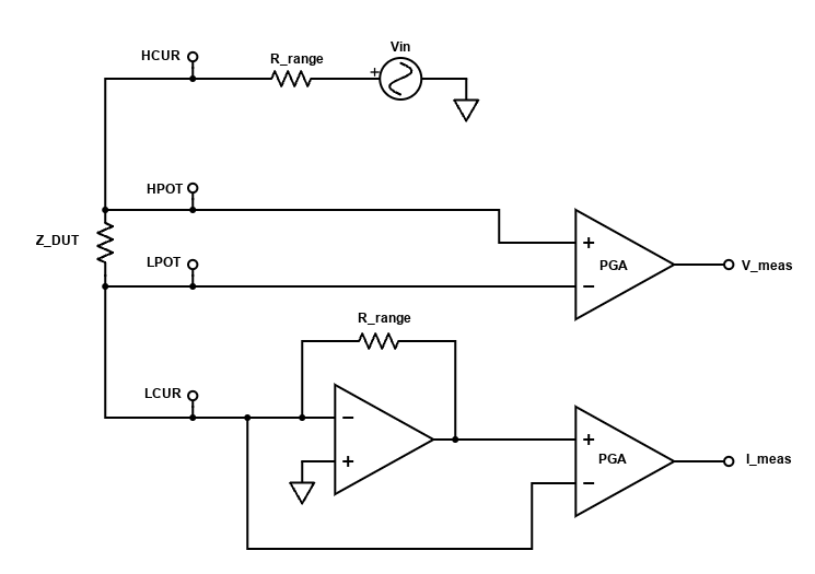
A couple circuit nuances:
Further analysis of this design can be found in this TI reference design: https://www.ti.com/lit/ug/tidueu6b/tidueu6b.pdf
The DUT voltage and current values are sampled via simultaneous ADCs. These temporal measurements must then be converted into phasors in order to perform the calculations outlined in the previous section. The method used to achieve this conversion is I-Q demodulation.
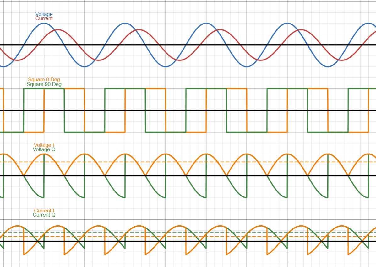
At the top, we start with our temporal voltage and current measurements. We then generate two square waves offset by 90° from each other at the same frequency as the voltage applied to the DUT. We then multiply these two square waves by the voltage and current waveforms to generate "I" and "Q" waveforms for the both voltage and current measurements. We can then integrate each of these over a large number of periods to determine the average values of each waveform.
The averaged values are used to construct two complex numbers, $I_V+jQ_V$ and $I_I+jQ_I$, which are the phasor representations of the voltage and current waveforms. Thus the DUT impedance can be calculated via
Z_{DUT}=\frac{I_V+jQ_V}{I_I+jQ_I}An interactive demo of this process can be found here: https://www.desmos.com/calculator/hkwapyh1lp
Many thanks to the work of WeTec/wschuma. Much of the audio codec design and firmware was based on their work on EEVblog and Github https://www.eevblog.com/forum/projects/teensylcr-a-teensy-based-diy-lcr-meter/ https://github.com/wschuma/TeensyLCR
In order to maximize SNR, the system will automatically switch between 4 transimpedance amplifier gains. These gains are 100Ω, 1kΩ, 10kΩ, and 100kΩ. For derivative projects, I would recommend switching to reed relays instead of analog muxes. At high frequenies on the 100kΩ range, the input signal is heavily attenuated
| Qty | Value | Footprint | References |
|---|---|---|---|
| 15 | 100n | Capacitor_SMD:C_0805_2012Metric | C10, C27, C34, C35, C36, C37, C38, C39, C40, C41, C42, C43, C45, C50, C51 |
| 11 | 1k | Resistor_SMD:R_0805_2012Metric | R13, R14, R15, R30, R34, R36, R42, R52, R53, R54, R55 |
| 10 | 10k | Resistor_SMD:R_0805_2012Metric | R22, R23, R29, R37, R43, R58, R59, R61, R62, R65 |
| 9 | 100 | Resistor_SMD:R_0805_2012Metric | R4, R5, R31, R35, R47, R51, R60, R63, R64 |
| 8 | 1u | Capacitor_SMD:C_0805_2012Metric | C6, C9, C20, C21, C22, C24, C47, C49 |
| 7 | 1p | Capacitor_SMD:C_0805_2012Metric | C1, C2, C16, C17, C25, C26, C32 |
| 6 | 8.2k | Resistor_SMD:R_0805_2012Metric | R1, R8, R21, R24, R44, R48 |
| 5 | 0 | Resistor_SMD:R_0805_2012Metric | R32, R33, R39, R40, R66 |
| 4 | .1u | Capacitor_SMD:C_0805_2012Metric | C7, C8, C46, C48 |
| 4 | 1.6k | Resistor_SMD:R_0805_2012Metric | R2, R7, R45, R49 |
| 4 | 1206L012WR | Fuse:Fuse_1206_3216Metric | F1, F2, F3, F4 |
| 4 | 1M | Resistor_SMD:R_0805_2012Metric | R9, R10, R17, R41 |
| 4 | 22 | Resistor_SMD:R_0805_2012Metric | R16, R18, R56, R57 |
| 4 | 300 | Resistor_SMD:R_0805_2012Metric | R3, R6, R46, R50 |
| 4 | 470p | Capacitor_SMD:C_0805_2012Metric | C3, C4, C28, C29 |
| 4 | 47u | Capacitor_SMD:CP_Elec_5x5.9 | C18, C19, C23, C44 |
| 4 | Conn_Coaxial | Connector_Coaxial:BNC_Amphenol_B6252HB-NPP3G-50_Horizontal | J1, J2, J3, J4 |
| 4 | ESD7205 | Package_TO_SOT_SMD:SOT-323_SC-70 | D8, D9, D10, D11 |
| 4 | MountingHole_Pad | MountingHole:MountingHole_3.2mm_M3_ISO14580_Pad_TopBottom | H1, H2, H3, H4 |
| 3 | 100k | Resistor_SMD:R_0805_2012Metric | R28, R38, R67 |
| 3 | 100p | Capacitor_SMD:C_0805_2012Metric | C11, C13, C31 |
| 2 | 2.7n | Capacitor_SMD:C_0805_2012Metric | C5, C30 |
| 2 | 3.3k | Resistor_SMD:R_0805_2012Metric | R25, R26 |
| 2 | 33p | Capacitor_SMD:C_0805_2012Metric | C14, C15 |
| 2 | 5.1k | Resistor_SMD:R_0805_2012Metric | R19, R20 |
| 2 | DG2034EDQ | Others:MSOP-10_largecorner | U9, U12 |
| 2 | DG4052EEQ | Package_SO:TSSOP-16_4.4x5mm_P0.65mm | U4, U14 |
| 2 | DMG1012UWQ-7 | Package_TO_SOT_SMD:SOT-323_SC-70 | Q1, Q2 |
| 2 | D_Schottky | Diode_SMD:Nexperia_CFP3_SOD-123W | D3, D4 |
| 2 | MC7805 | Package_TO_SOT_SMD:TO-252-2 | U10, U11 |
| 2 | OPA2365AIDR | Package_SO:SOIC-8_3.9x4.9mm_P1.27mm | U1, U13 |
| 2 | THS4561IDGKR | Package_SO:TSSOP-8_3x3mm_P0.65mm | U2, U15 |
| 2 | TLV9161IDBVR | Package_TO_SOT_SMD:SOT-23-5 | U7, U16 |
| 1 | 10u | Capacitor_SMD:C_0805_2012Metric | C33 |
| 1 | 220p | Capacitor_SMD:C_0805_2012Metric | C12 |
| 1 | 5VA | Others:testpoint_0805 | TP12 |
| 1 | 5VD | Others:testpoint_0805 | TP13 |
| 1 | 7.5V | Diode_SMD:Nexperia_CFP3_SOD-123W | D1 |
| 1 | Barrel_Jack_Switch | Connector_BarrelJack:BarrelJack_GCT_DCJ200-10-A_Horizontal | J7 |
| 1 | Buzzer | Buzzer_Beeper:Buzzer_12x9.5RM7.6 | BZ1 |
| 1 | CS4272 | Package_SO:TSSOP-28_4.4x9.7mm_P0.65mm | U3 |
| 1 | Conn_01x02_Pin | Connector_PinHeader_2.54mm:PinHeader_1x02_P2.54mm_Vertical | J10 |
| 1 | Conn_01x06_Pin | Connector_PinHeader_2.54mm:PinHeader_1x06_P2.54mm_Vertical | J5 |
| 1 | Conn_01x09_Pin | Connector_PinHeader_2.54mm:PinHeader_1x09_P2.54mm_Vertical | J8 |
| 1 | Conn_01x14_Pin | Connector_PinHeader_2.54mm:PinHeader_1x14_P2.54mm_Vertical | J9 |
| 1 | Crystal | Crystal:Crystal_SMD_ECS_CSM3X-2Pin_7.6x4.1mm | Y1 |
| 1 | DAC+ | Others:testpoint_0805 | TP5 |
| 1 | DAC- | Others:testpoint_0805 | TP6 |
| 1 | DMP3099L | Package_TO_SOT_SMD:SOT-23 | Q3 |
| 1 | D_Schottky | Diode_SMD:D_0805_2012Metric | D6 |
| 1 | IPGA+ | Others:testpoint_0805 | TP8 |
| 1 | IPGA- | Others:testpoint_0805 | TP9 |
| 1 | ISNS+ | Others:testpoint_0805 | TP1 |
| 1 | ISNS- | Others:testpoint_0805 | TP2 |
| 1 | Jumper_2_Open | Connector_PinHeader_2.54mm:PinHeader_1x02_P2.54mm_Vertical | JP1 |
| 1 | MCP9800Ax-xOT | Package_TO_SOT_SMD:SOT-23-5 | U6 |
| 1 | R_US | Resistor_SMD:R_0805_2012Metric | R27 |
| 1 | SCL | Others:testpoint_0805 | TP14 |
| 1 | SDA | Others:testpoint_0805 | TP15 |
| 1 | SIG | Others:testpoint_0805 | TP7 |
| 1 | SW_SPST | Connector_PinHeader_2.54mm:PinHeader_1x02_P2.54mm_Vertical | SW1 |
| 1 | Screw_Terminal_01x02 | TerminalBlock_Phoenix:TerminalBlock_Phoenix_MKDS-1,5-2-5.08_1x02_P5.08mm_Horizontal | J6 |
| 1 | TIA | Others:testpoint_0805 | TP16 |
| 1 | TLV9162IDR | Package_SO:SOIC-8_3.9x4.9mm_P1.27mm | U17 |
| 1 | Teensy4.1_mainpins | Teensy:Teensy41_mainpins | U5 |
| 1 | VMID | Others:testpoint_0805 | TP17 |
| 1 | VPGA+ | Others:testpoint_0805 | TP11 |
| 1 | VPGA- | Others:testpoint_0805 | TP10 |
| 1 | VSNS+ | Others:testpoint_0805 | TP3 |
| 1 | VSNS- | Others:testpoint_0805 | TP4 |


loozhengyuan/MitsubishiSC
Smart controller for Mitsubishi Electric HVAC systems.


jagdeepsingh02/ENNOID-Dual-Gate-Driver
Dual Gate Driver for IGBT or Mosfet modules


sdsmt-robotics/MotorSpeedController
setup() { ... // Init SPI SPI.begin (); SPI.setClockDivider(SPICLOCKDIV4);

It measures 100 × 100 mm and has 4 copper layers, 1.6 mm thick.
182 parts, built around the CS4272-CZZ, MC7805CT, 1206L012WR and ESD7205D. The full list of its parts is on this page, with links to each part's symbol and footprint where PCBKit's library has them.
From the Owen-Ball/LCR_Meter repository on GitHub, at the commit this page was made from: the board is PCB/KiCAD/lcr_v2/lcr.kicad_pcb and its schematic PCB/KiCAD/lcr/codec.kicad_sch. PCBKit opens the board in the browser, with nothing to install.
Its repository states no licence, so its author keeps all rights: ask Owen-Ball before reusing the design.